About this Build
The 1941 Plymouth Coupe is part of a build series I'm calling:
"America Goes to War". While I was doing research on building
the 1941 Pickup Truck I learned that in 1941, all U.S. car manufacturers
had the same situation; they were all converting their factories
over to produce military equipment for use in WWII.
The 1941 Plymouth, like the 1941 Chevy Pickup truck was the last
American built car for civilian use until after WWII
ended. This build in is tribute the men and women who worked
at the "big-3", Ford, GM and Chrysler that converted their
factories and their lives over to building military vehicles. As I
mentioned in the '41 Pickup build, Ford built a brand new plant
to produce the B-24 Liberator with converting it back to civilian cars
and trucks after the war.
I DID A HORRIBLE JOB ON THIS BUILD
I did a horrible job on this build. I'm still fairly low on the
learning curve and you'll be able to see a lot of the learning.
Some of the things that happened because I'm still learning:
- Body paint is orange peeled
- My shakiness on using a chrome pen for the first time
- Some of the smaller parts not pinned and wandering
- Some fo the smaller parts have mold lines
And I'm sure there are a ton more things I did wrong, but I'm
learning.
I like this car and have another one in my stash that I will be
building in the future.
View the issues I had with this kit
and how I fixed them
AMERICA GOES TO WAR
I got so excited about this I decided to build all three at
the same time:
- 1941 Chevy Pickup
- 1941 Plymouth Coup
- B24 Liberator
Click this link to read a brief history of the 1941's
Photo/Video/Assembly Journal
77 Photos
Skip's Messy Workbench ⇔ All rights reserved ⇔ Copyright © 2023-2025
Skip's Messy Workbench
⇔ Last updated: July 20, 2025

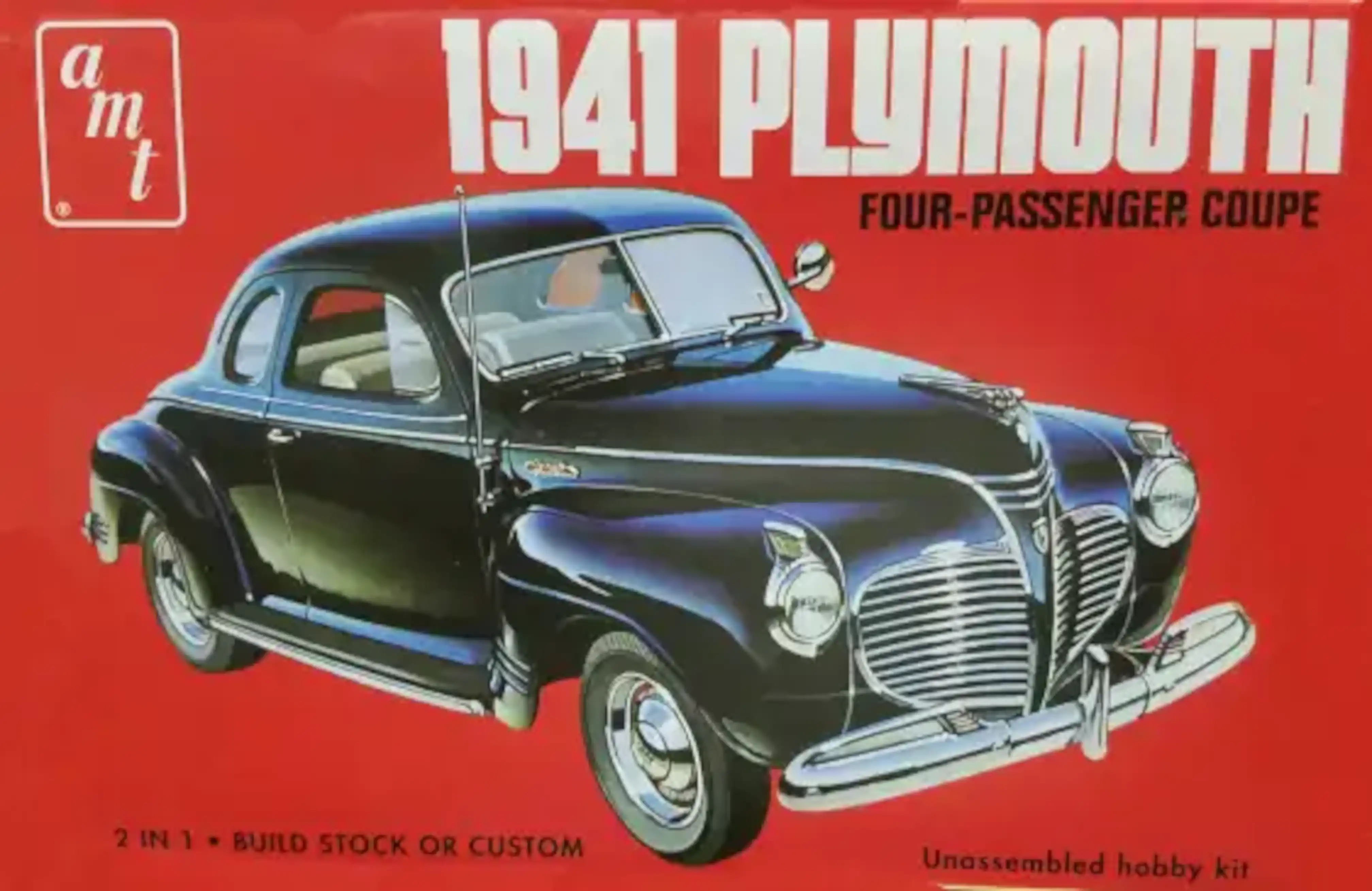 1941 Plymouth Coupe Box Art
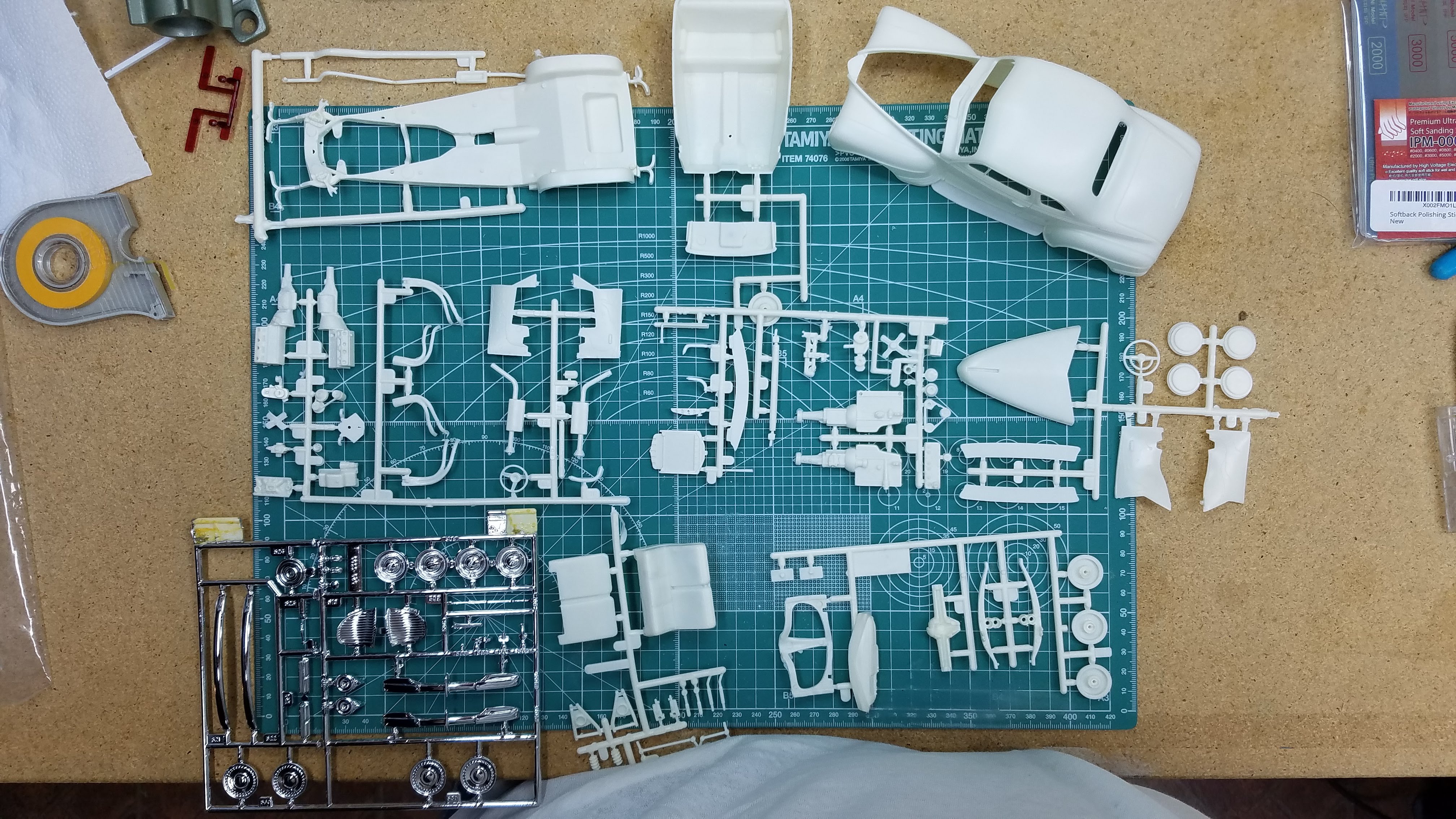 All parts and sprues are removed from the box
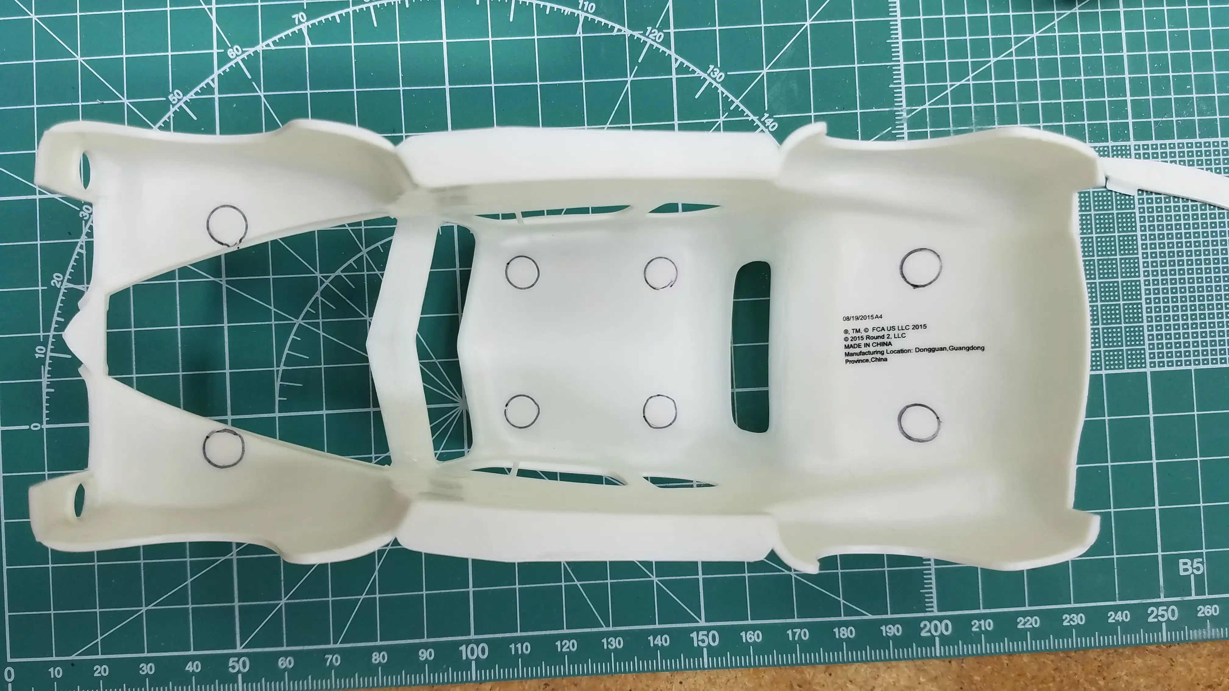 Marking ejector pin marks for removal
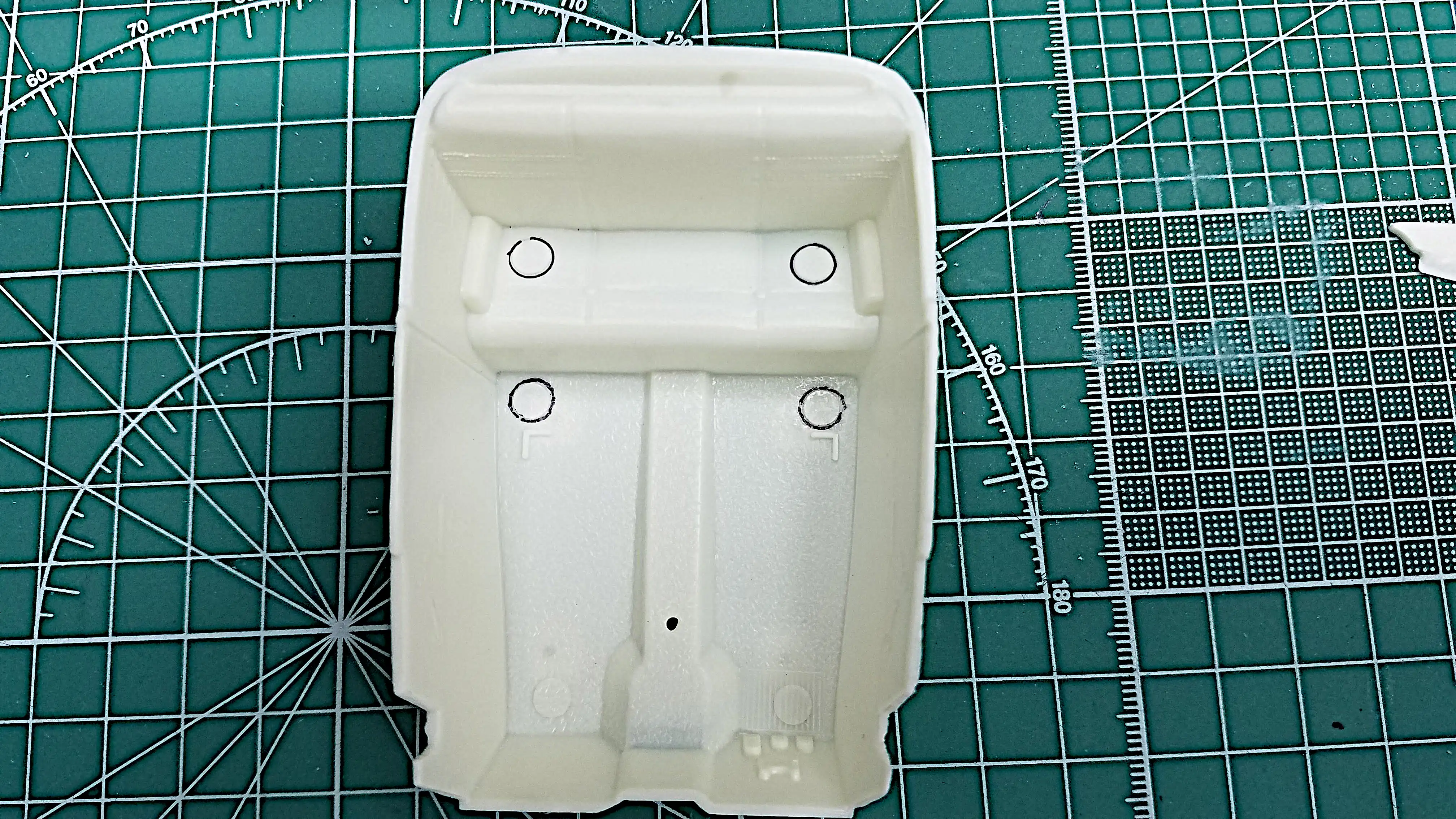 Marking ejector pin marks for removal
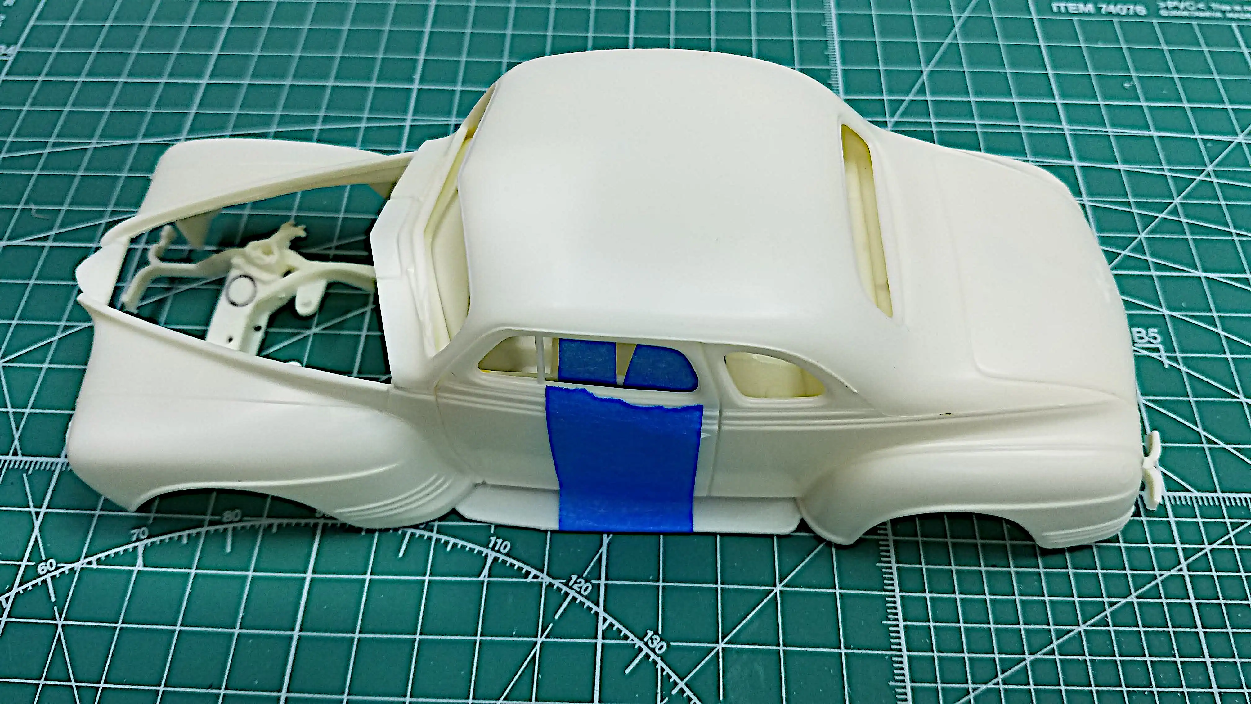 Dry fitting body, interior tub and frame
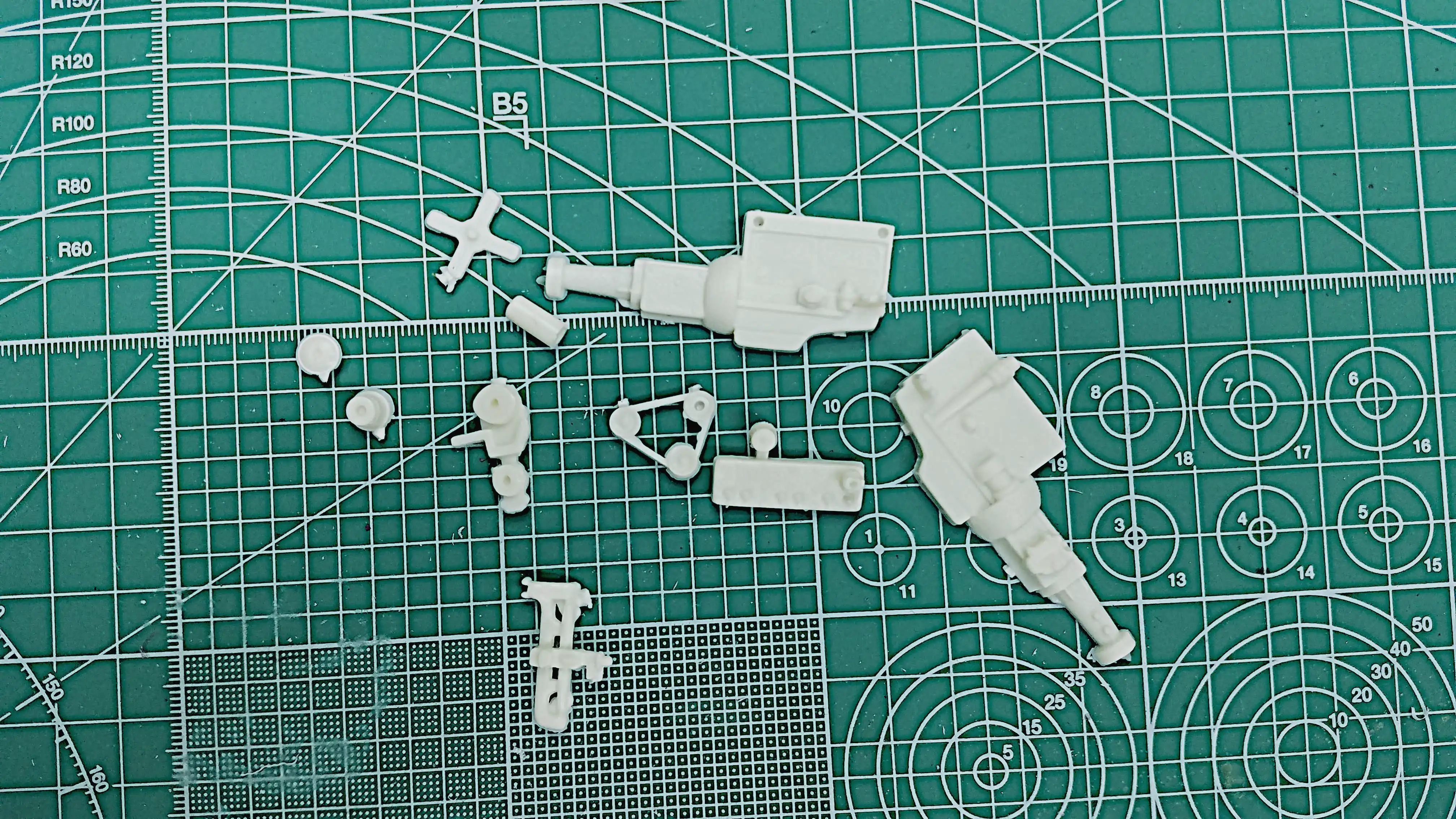 Removing engine parts from the sprues
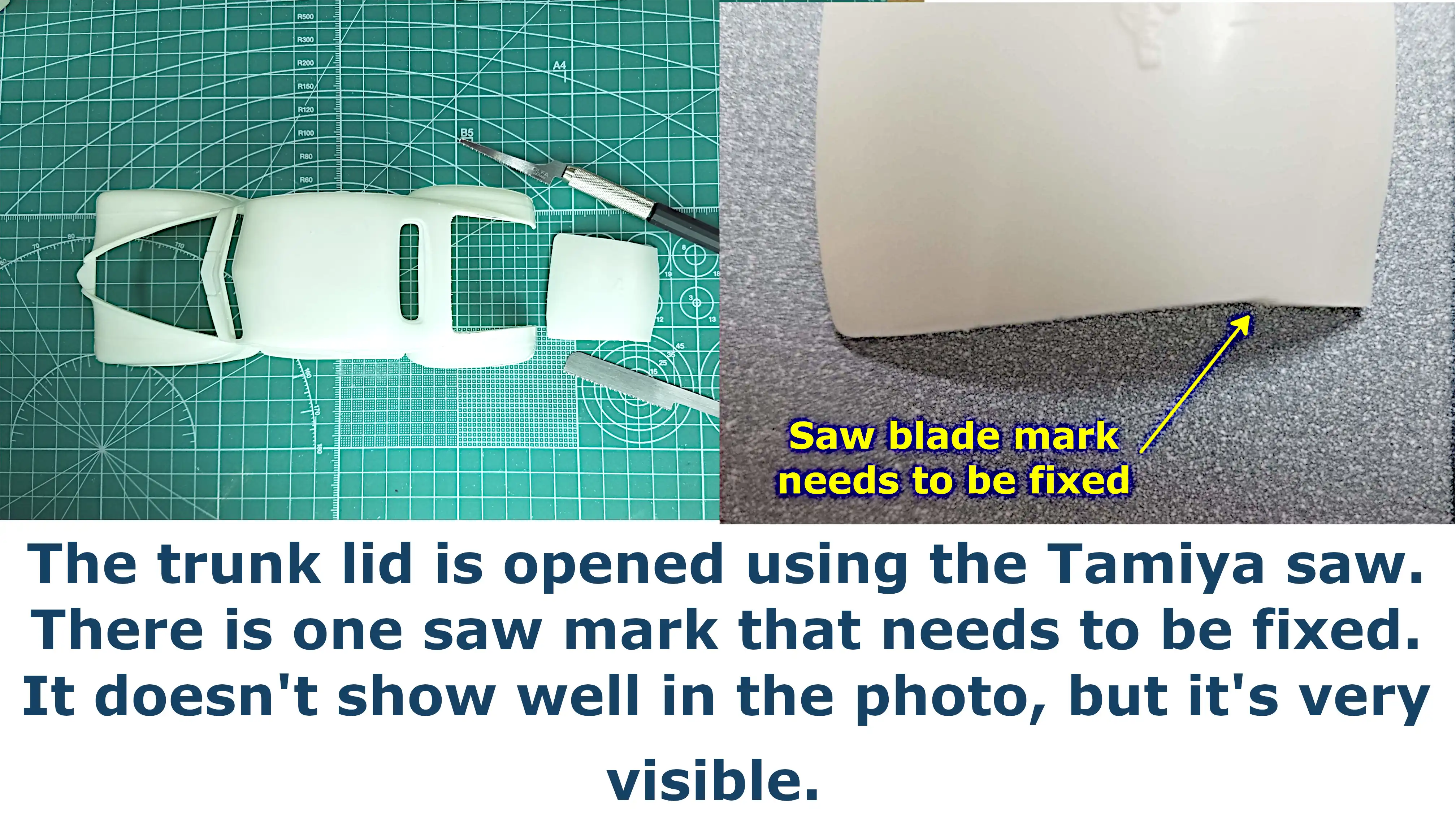 Trunk lid has been cut open
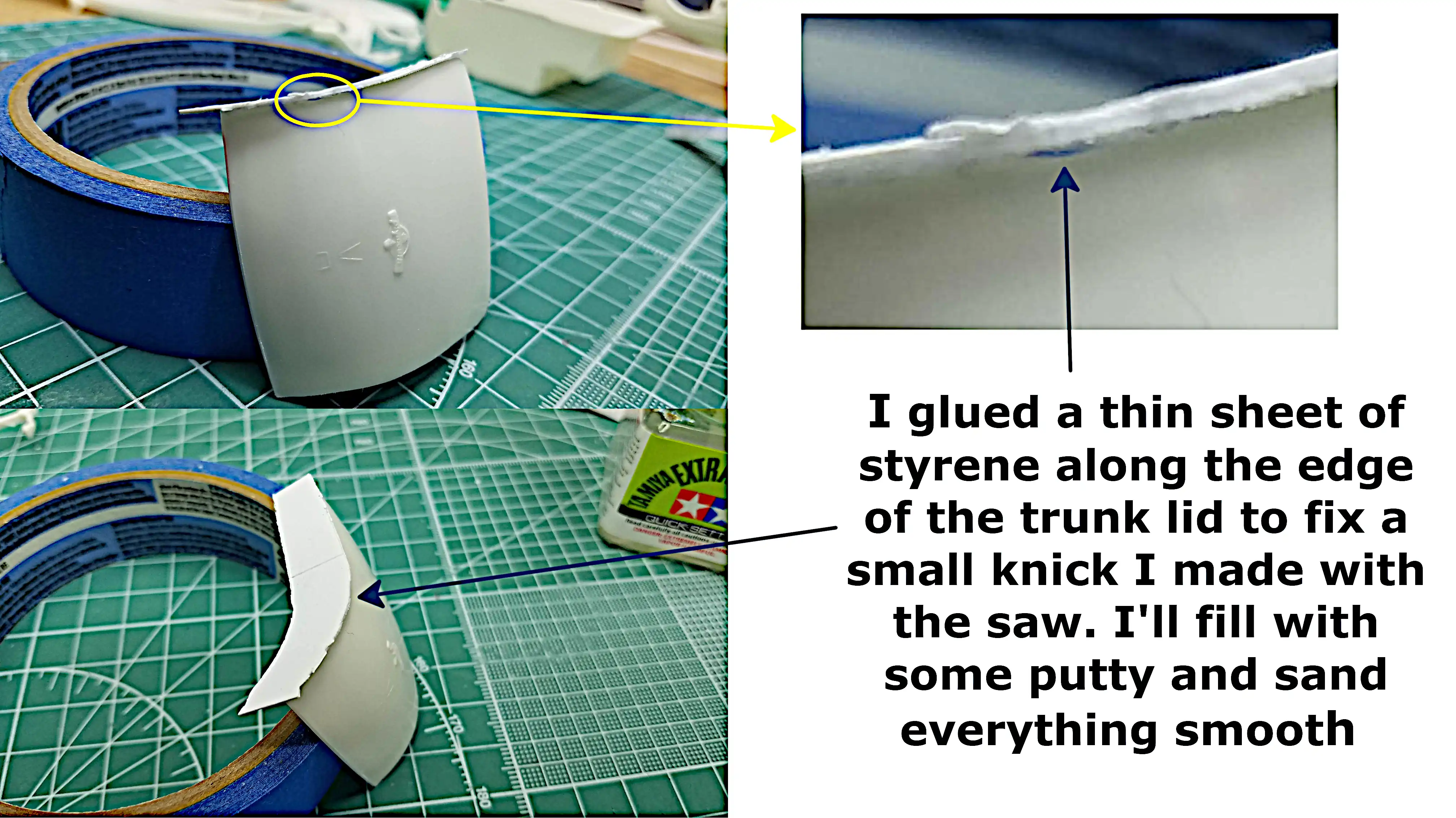 Repairing the trunk lid I damaged
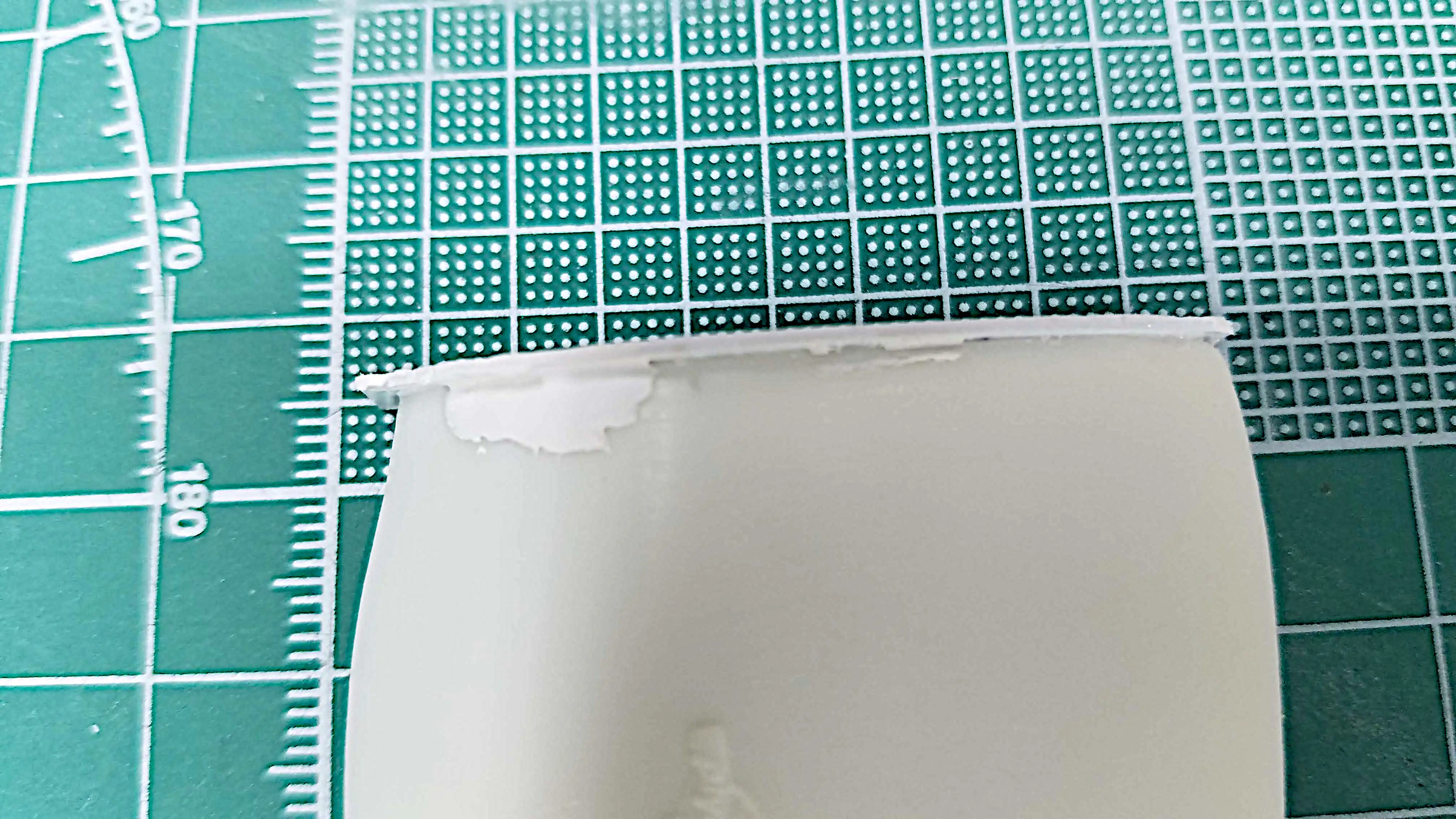 Repairing the trunk lid I damaged
 Fabricated and installed the inner trunk drip rails
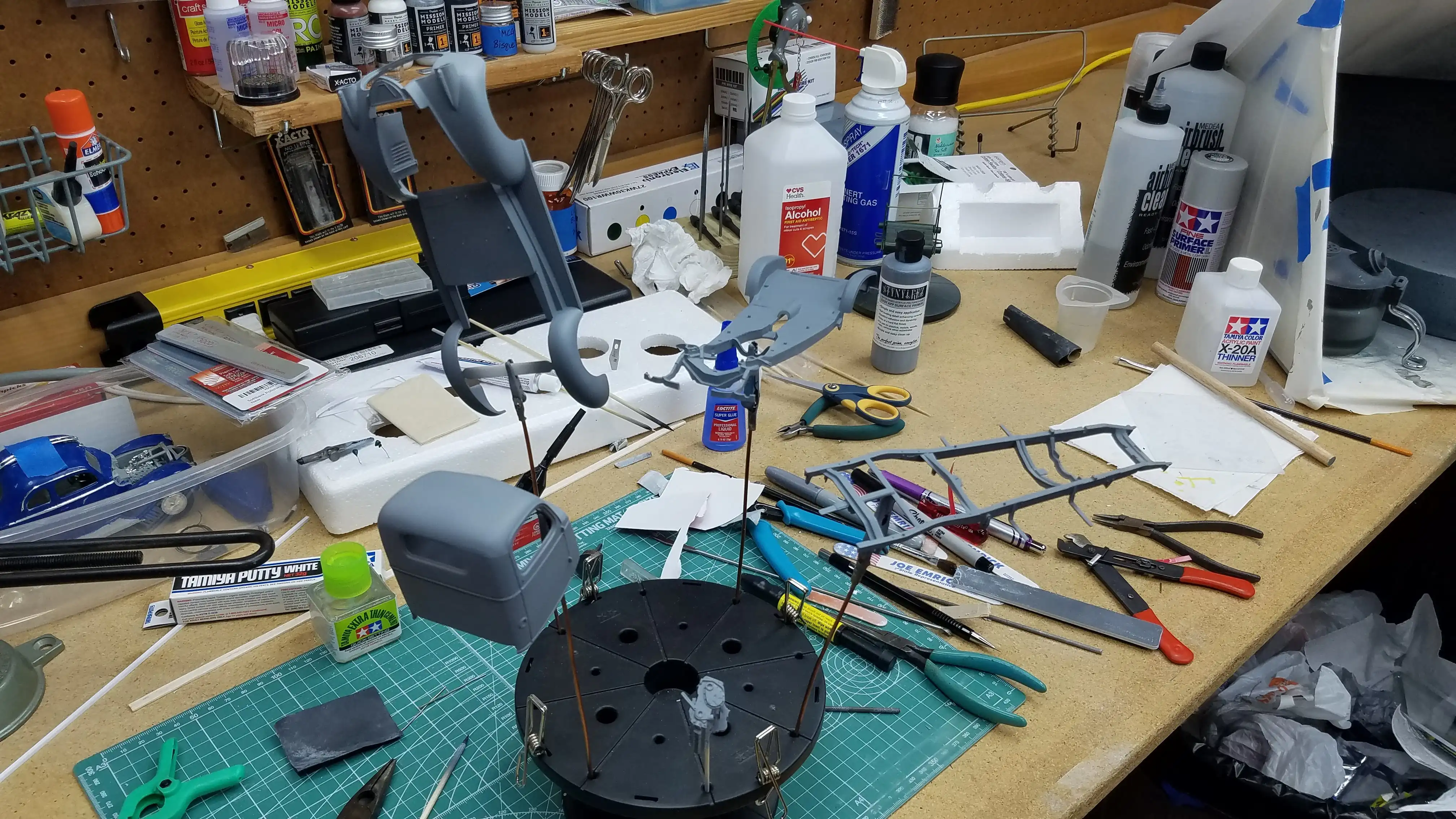
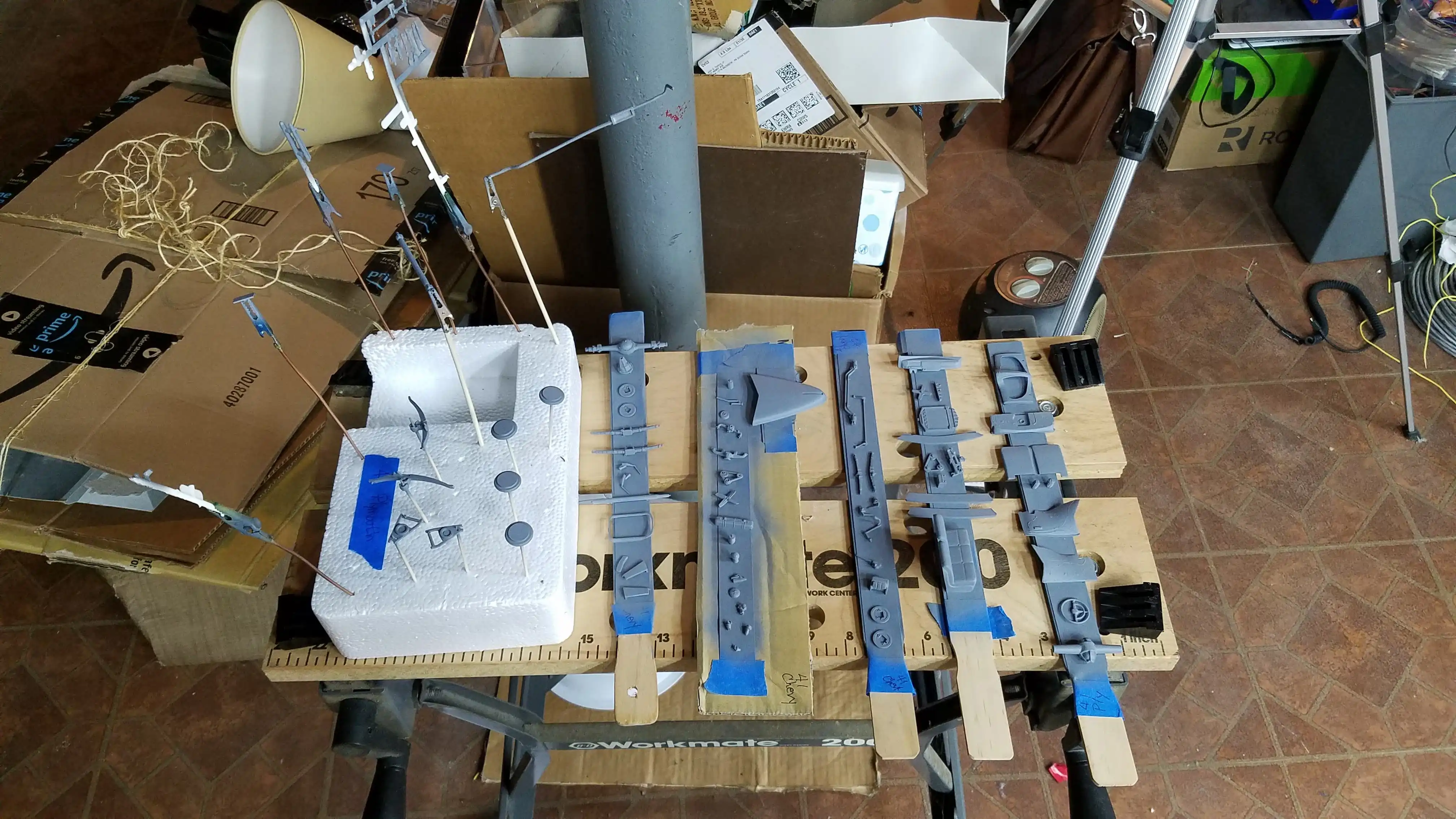
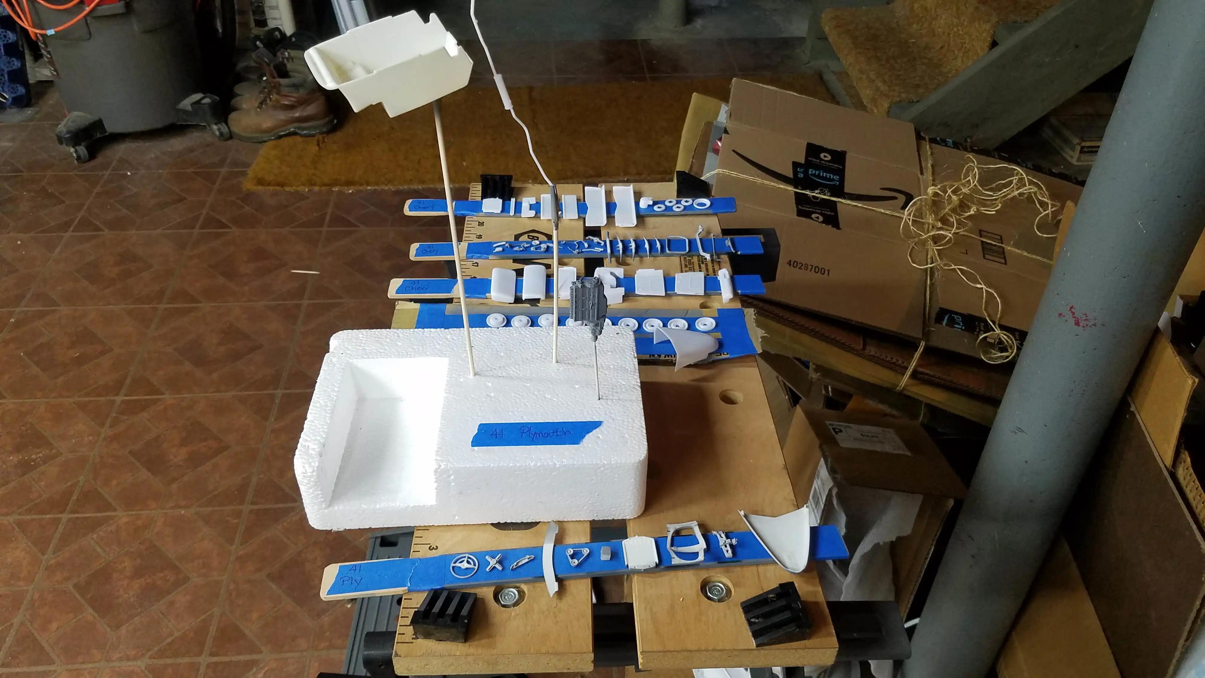
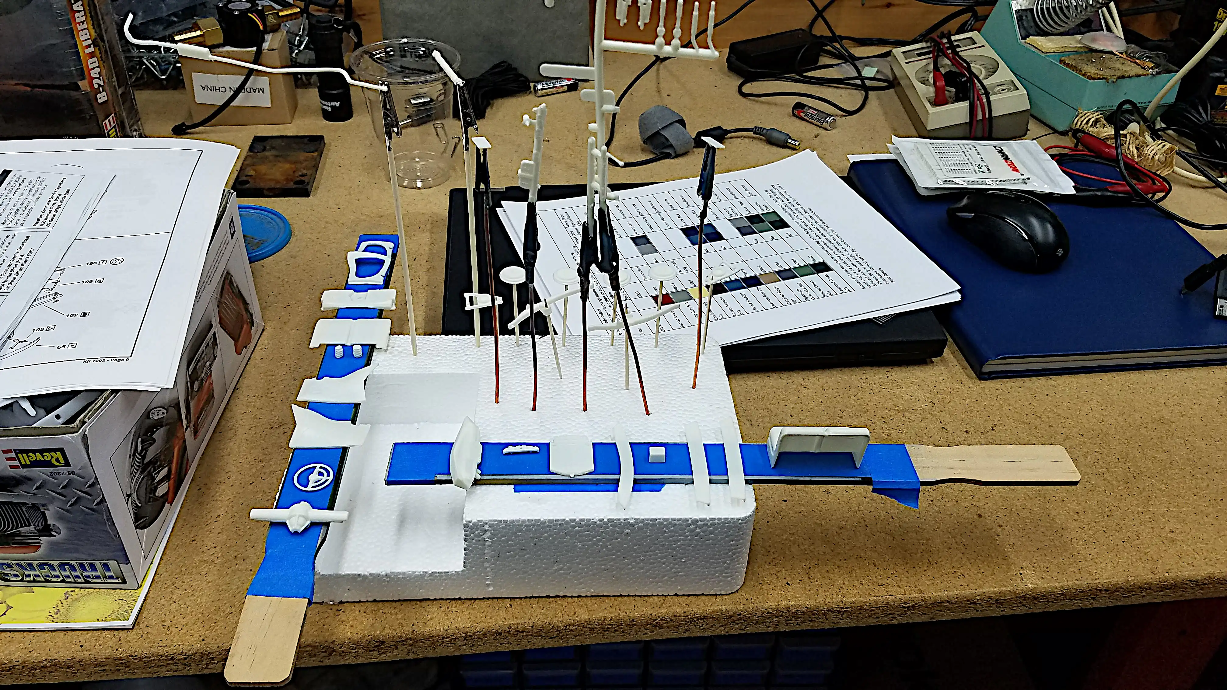 Parts are being prepared for first coat of primer
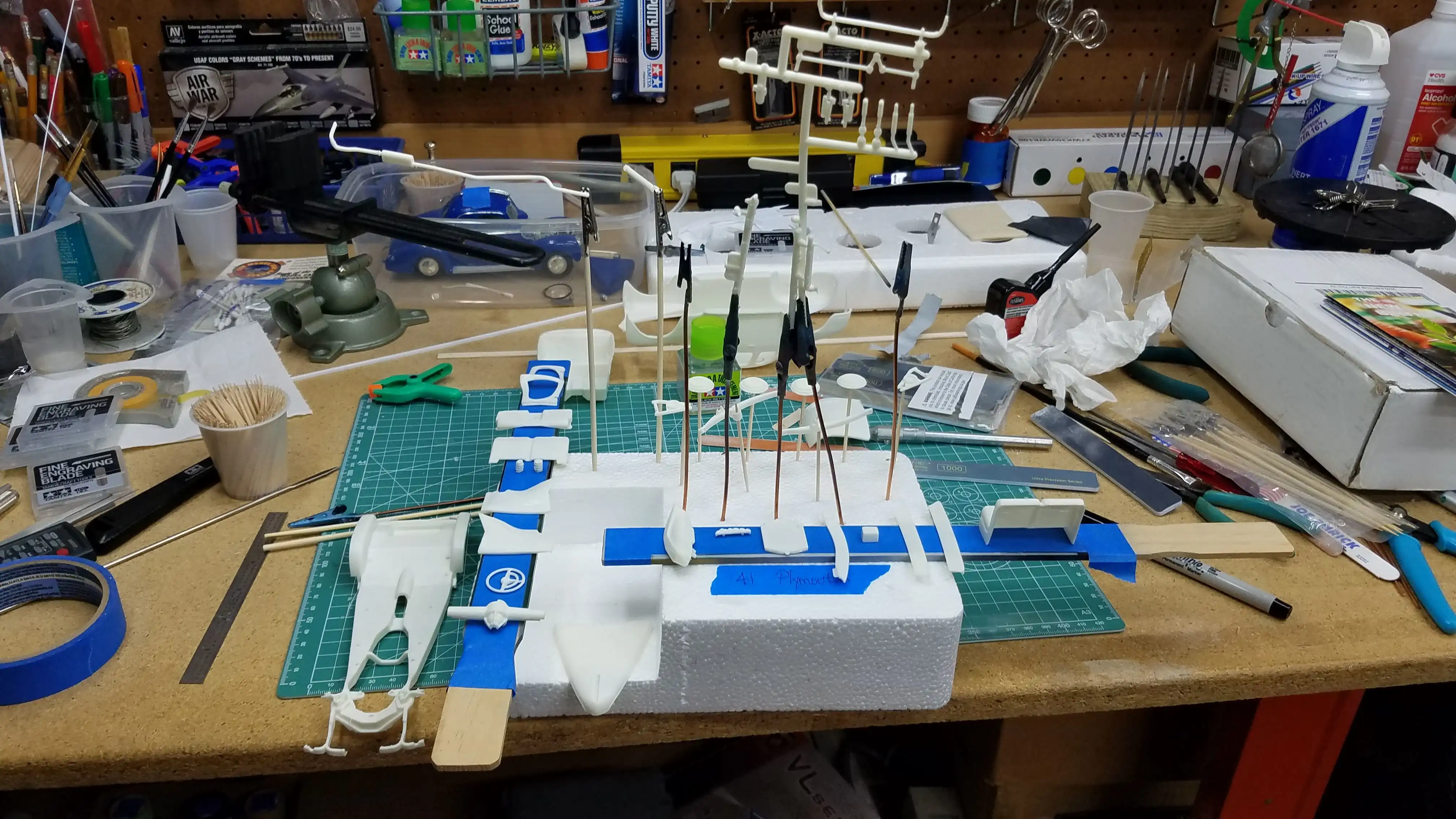 Parts are being prepared for the first coat of
primer.
Parts are being prepared for the first coat of
primer.
 Parts are being prepared for the first coat of
primer.
Parts are being prepared for the first coat of
primer.
 Parts have been primed
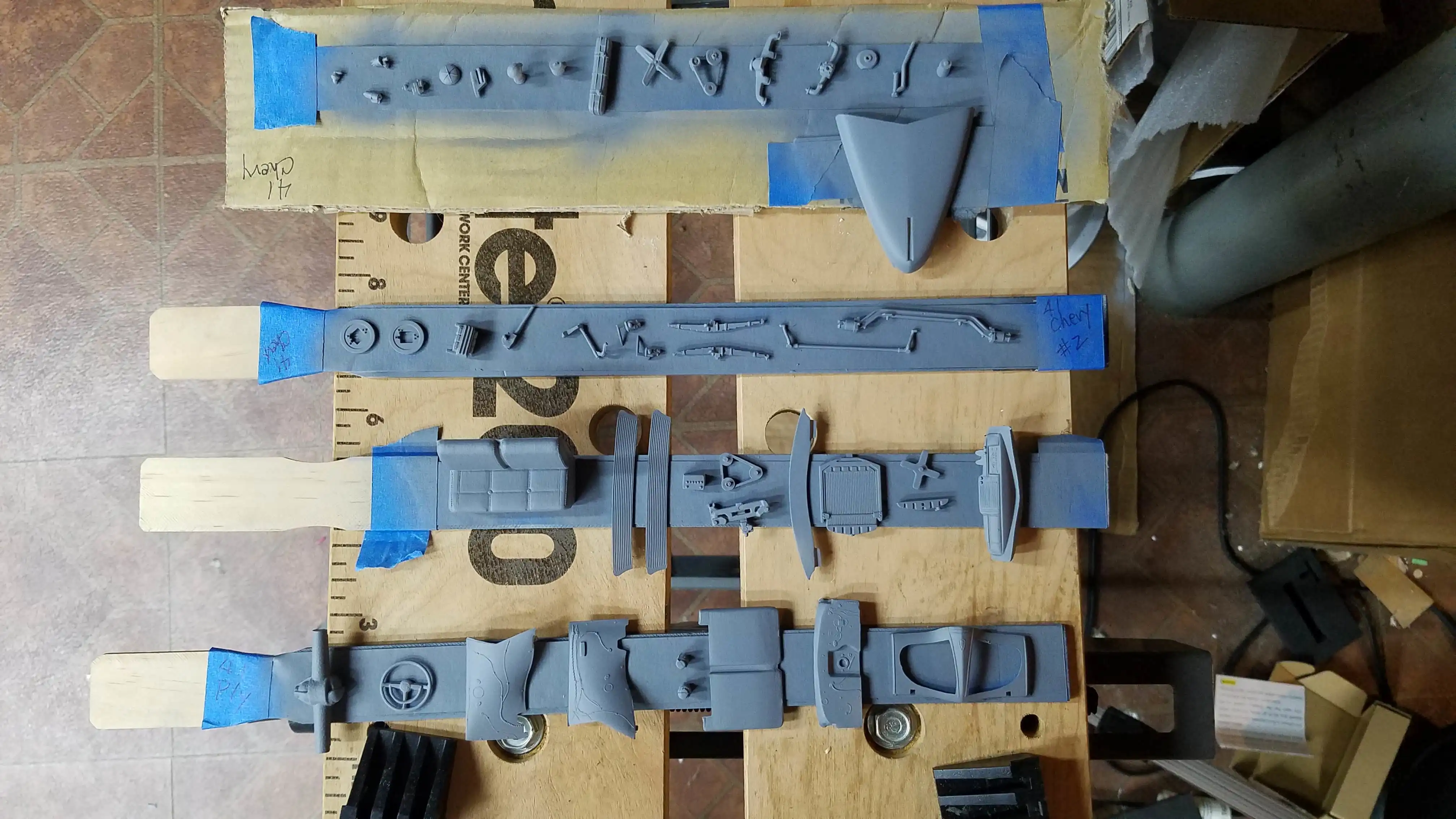 Parts have been primed
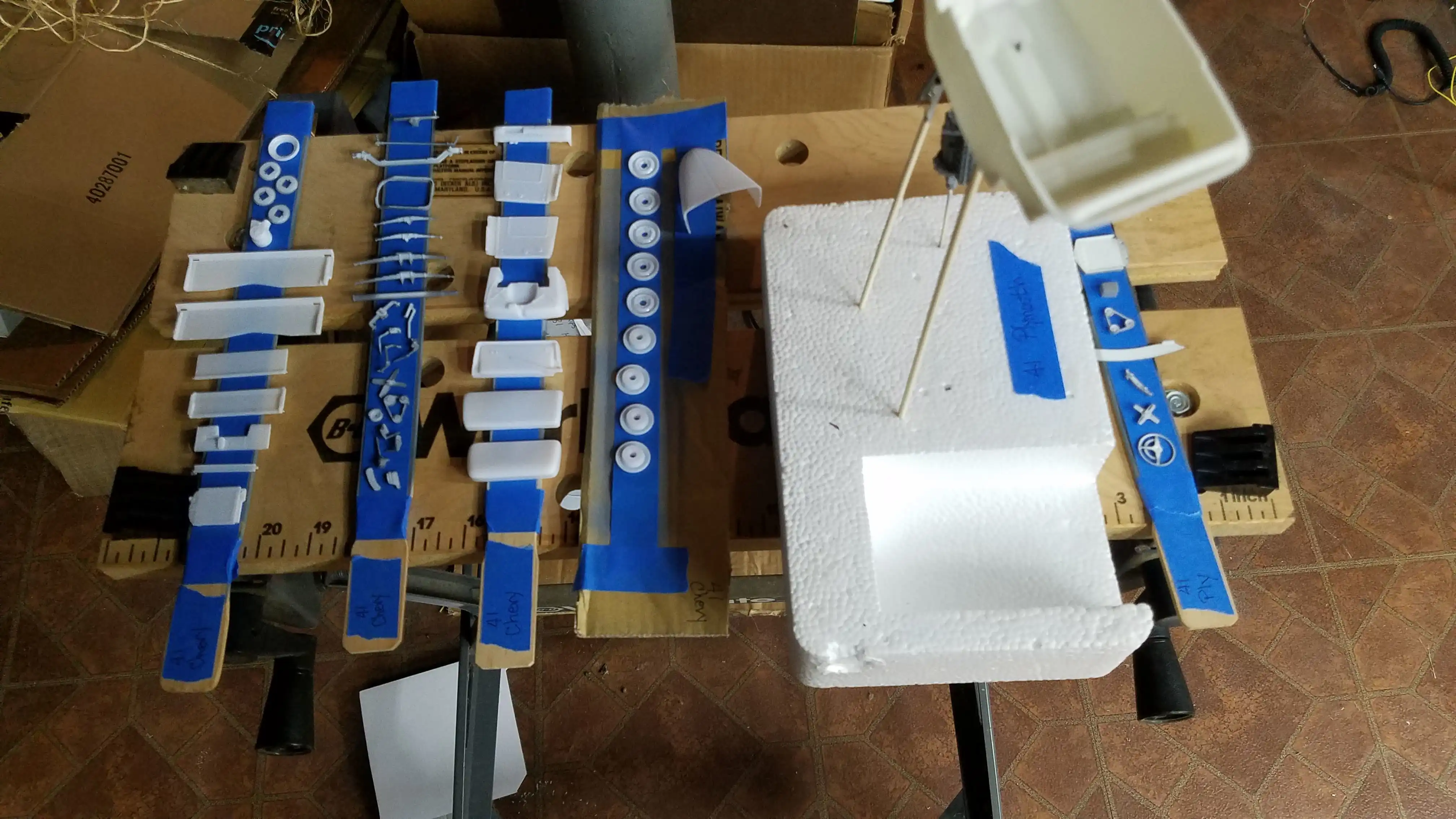 Additional parts need priming
 Additional parts need priming
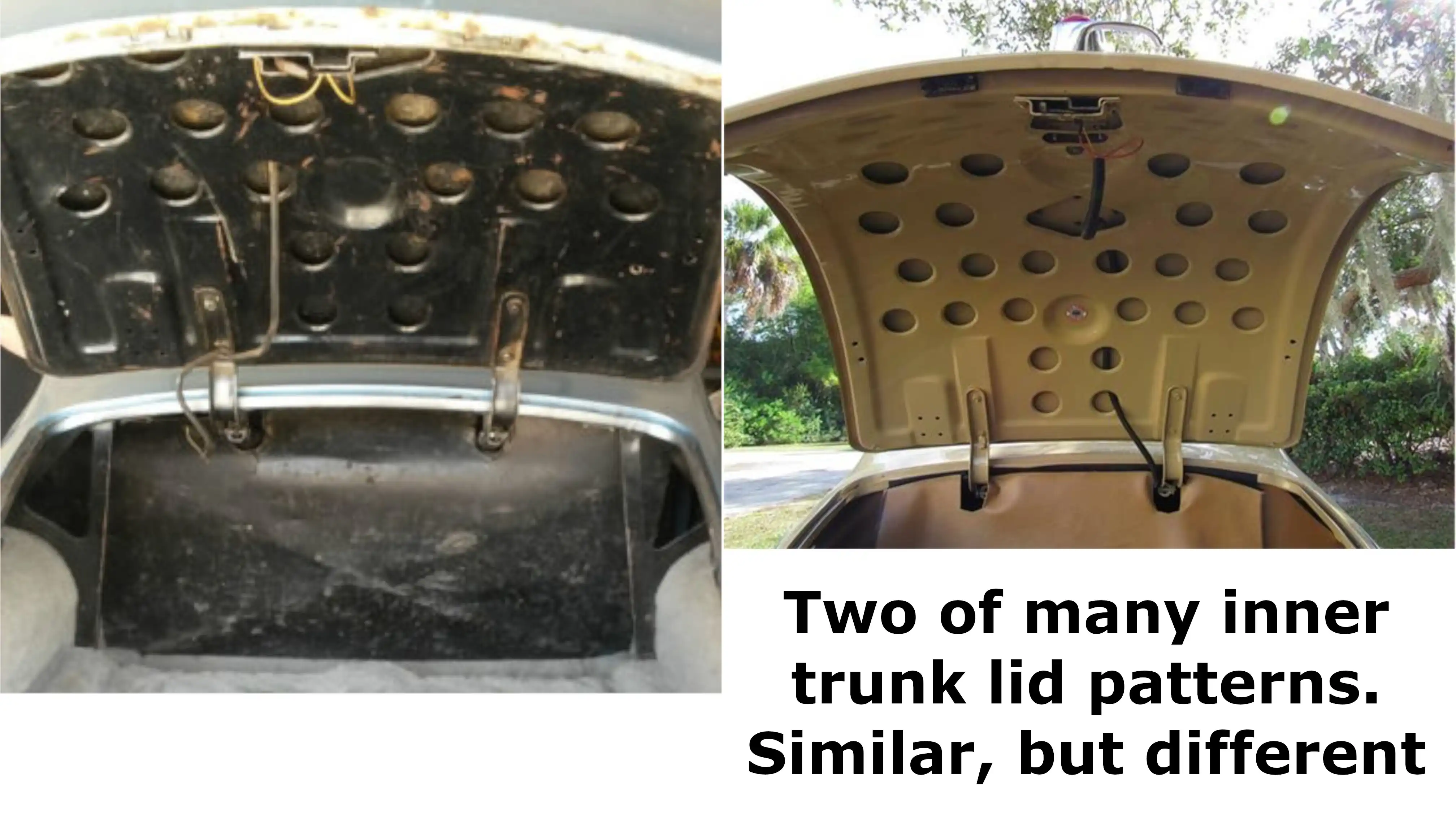 Researching the various trunk lid supports
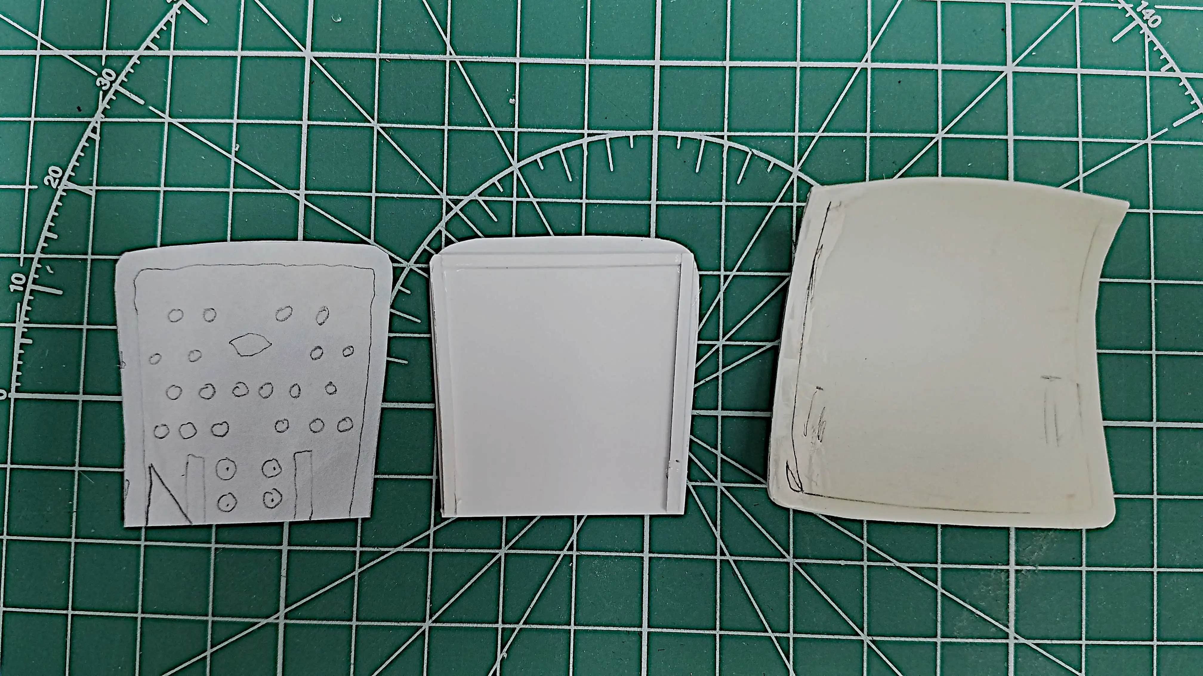 Laying out the underside of the trunk lid
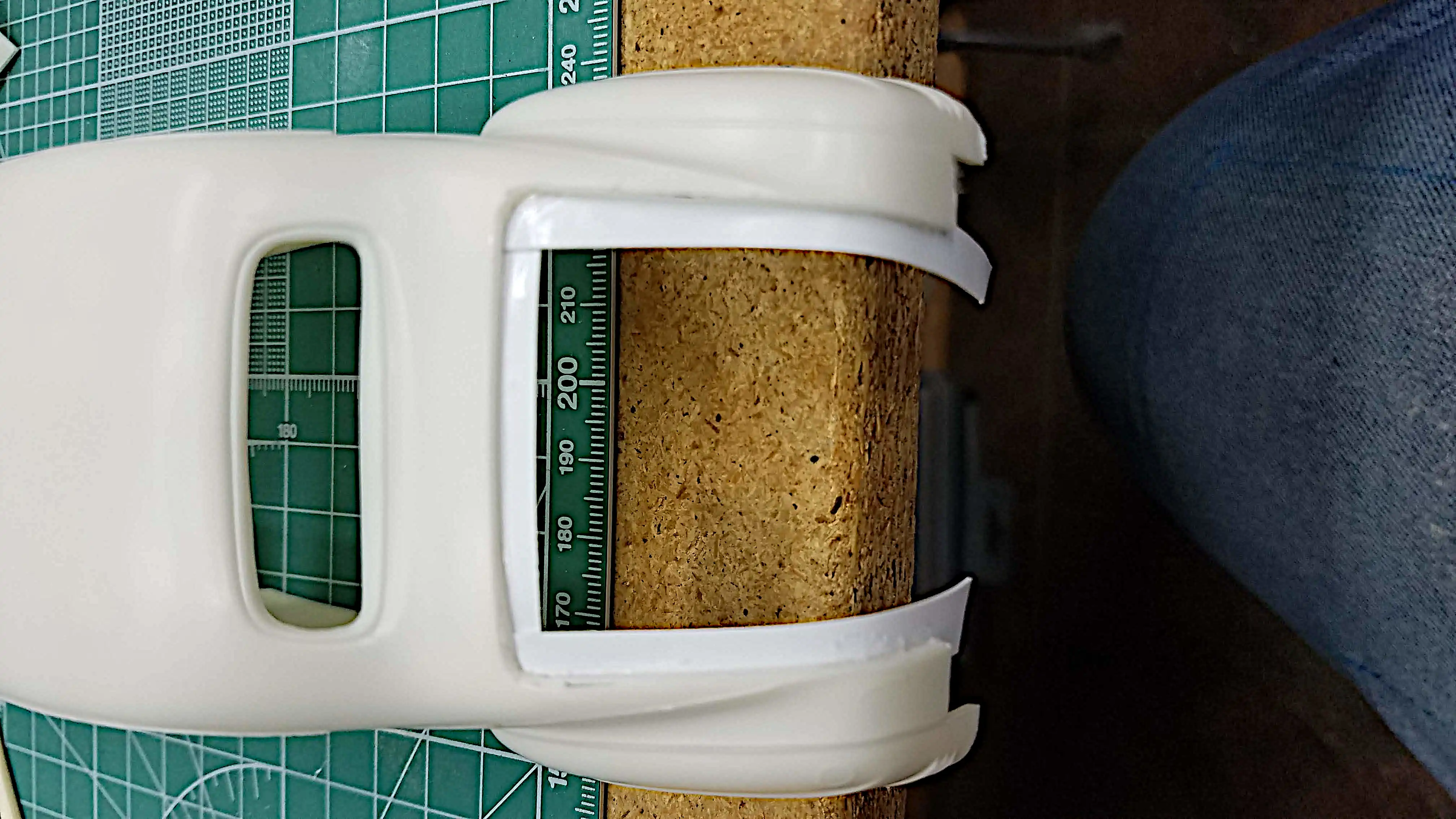
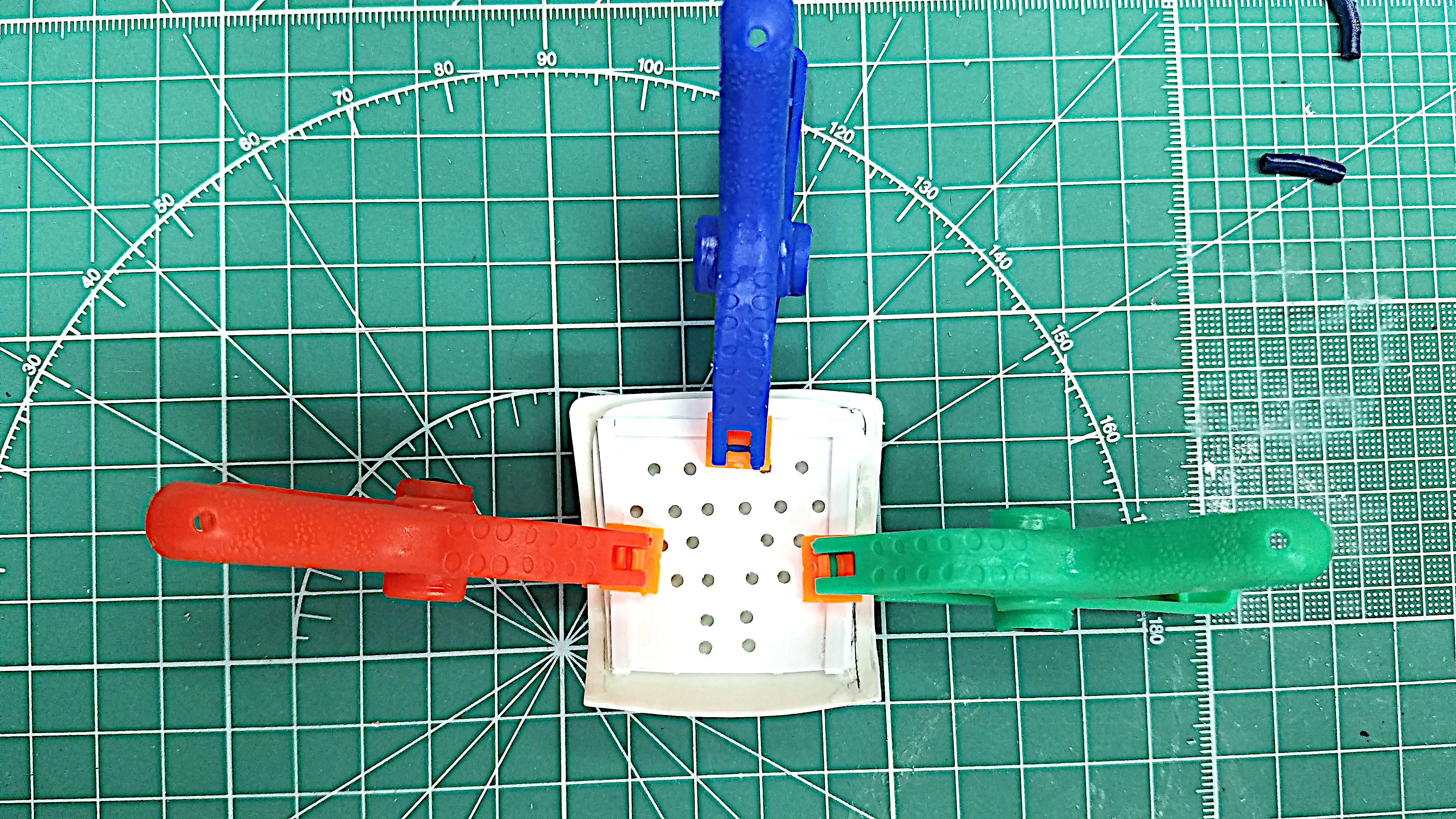 clamping my scratch built underside trunk lid in place
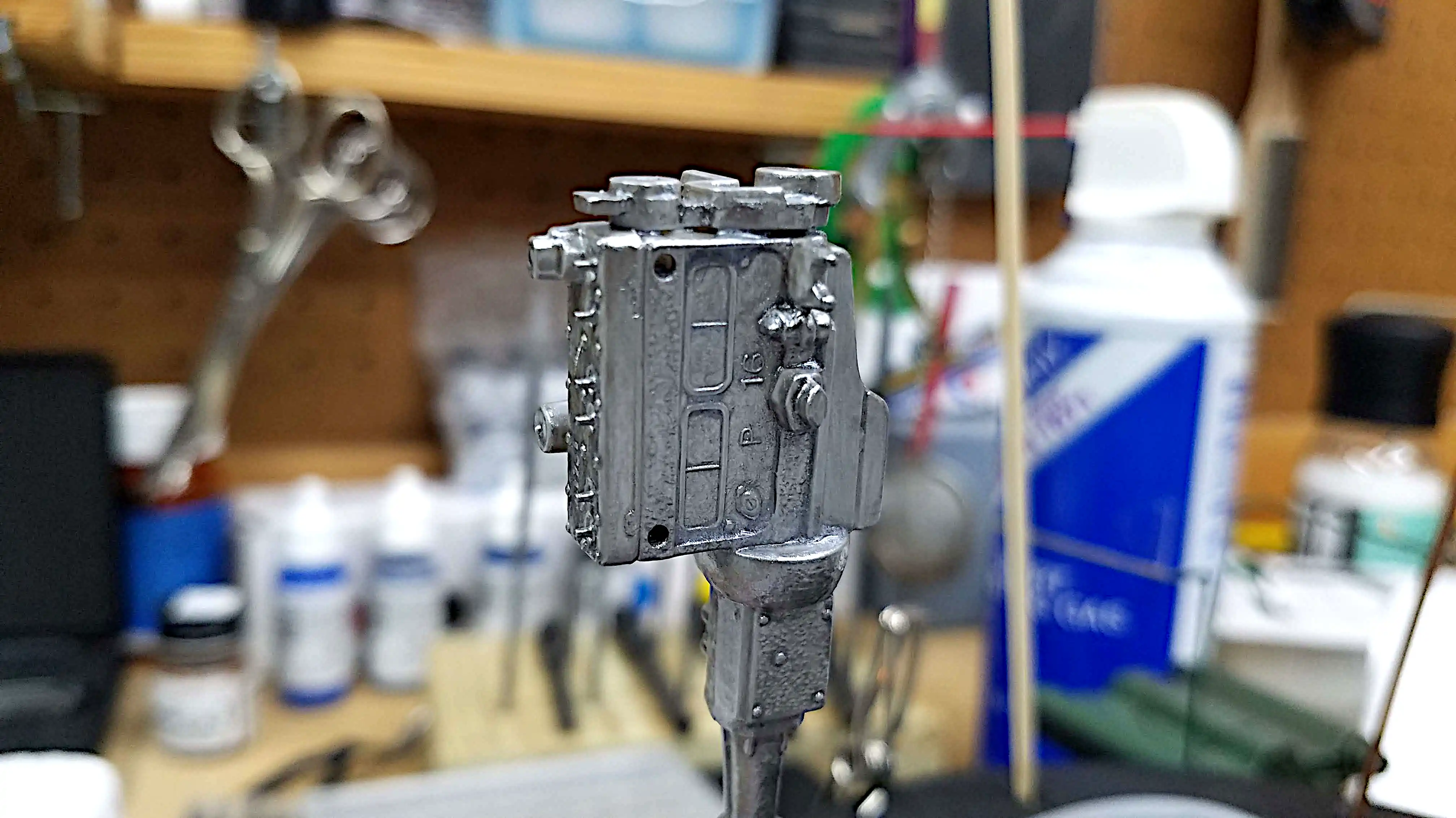 Painting the engine
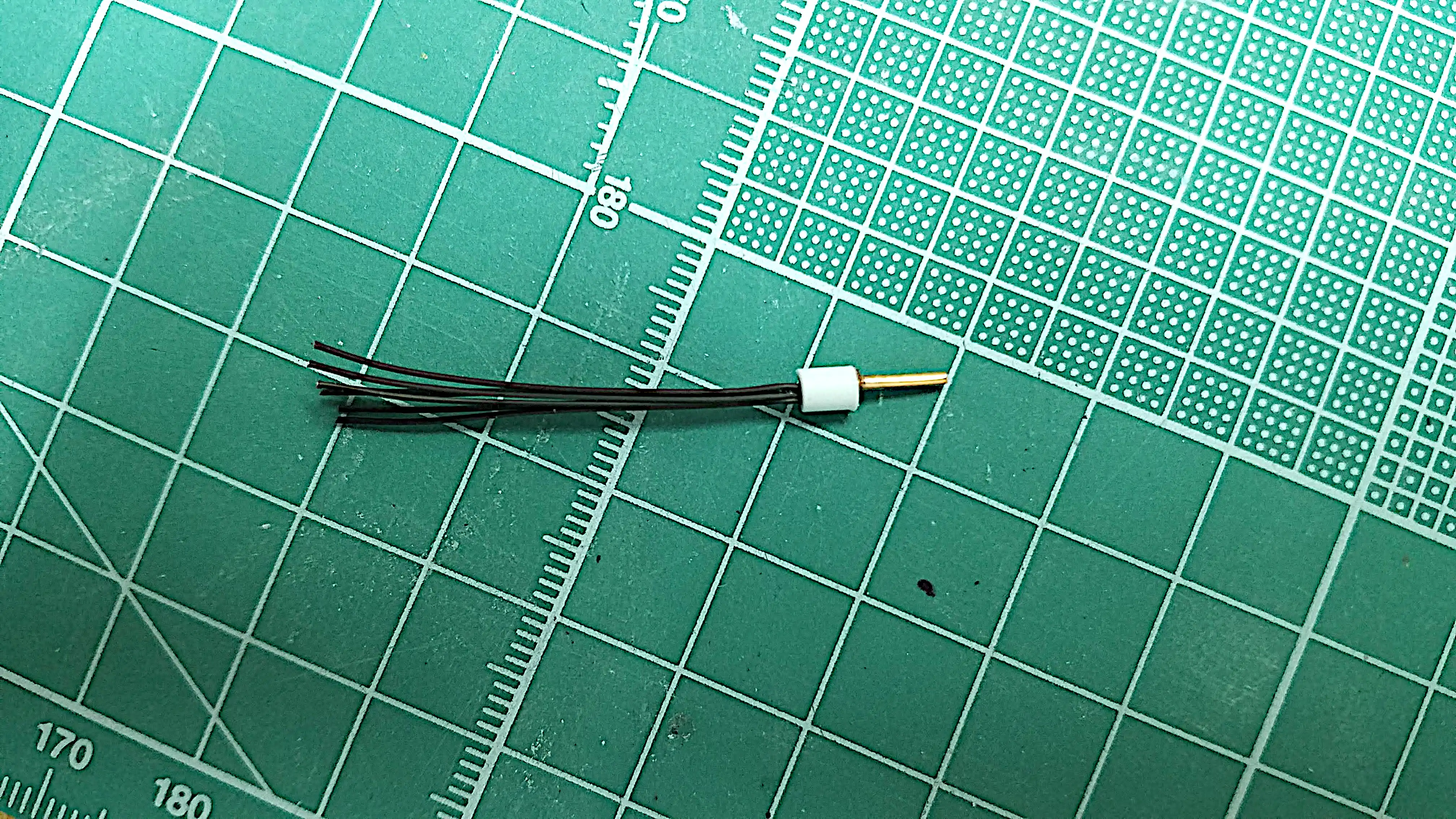 Scratch building a distributor
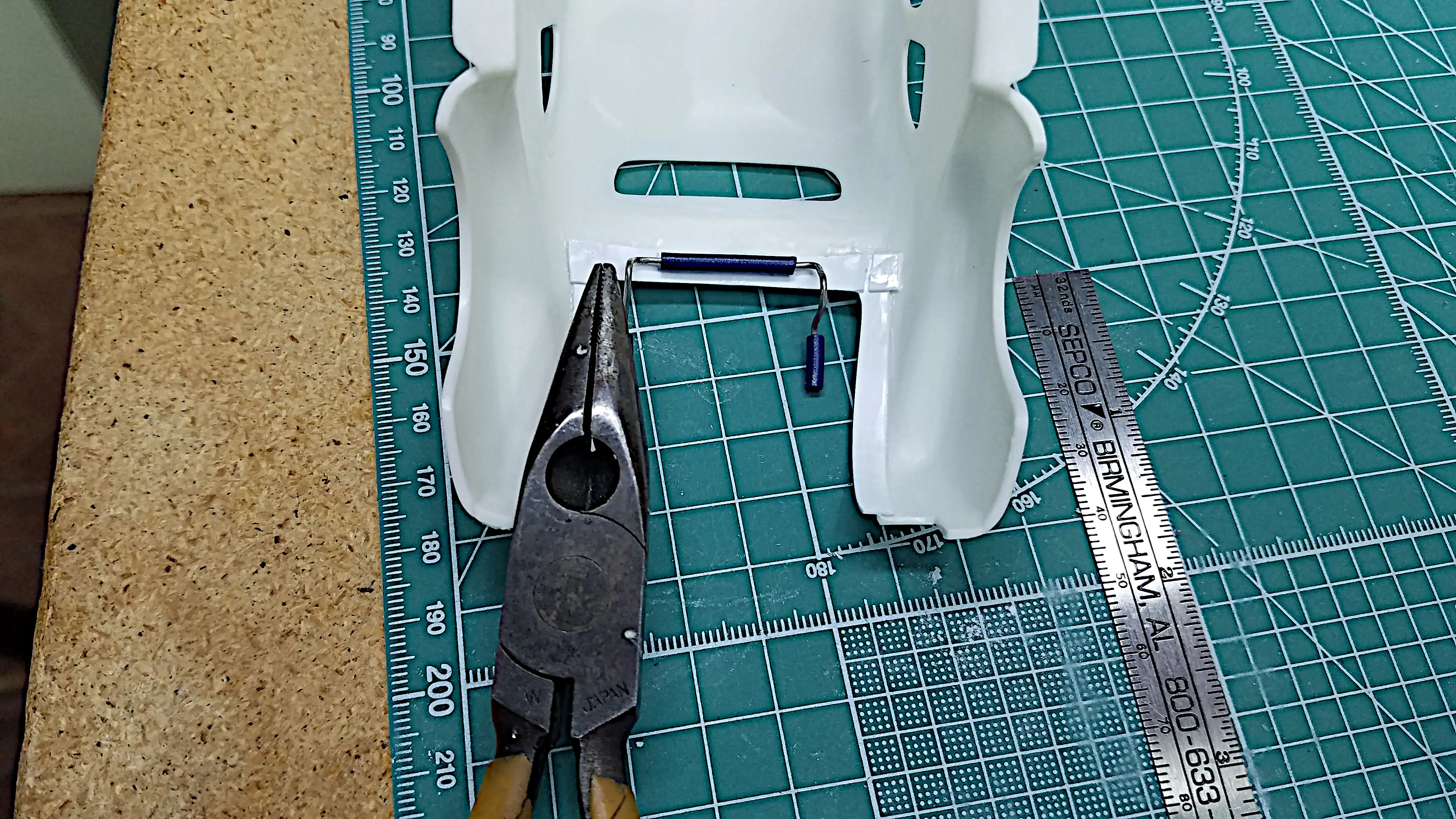 Making trunk hinges
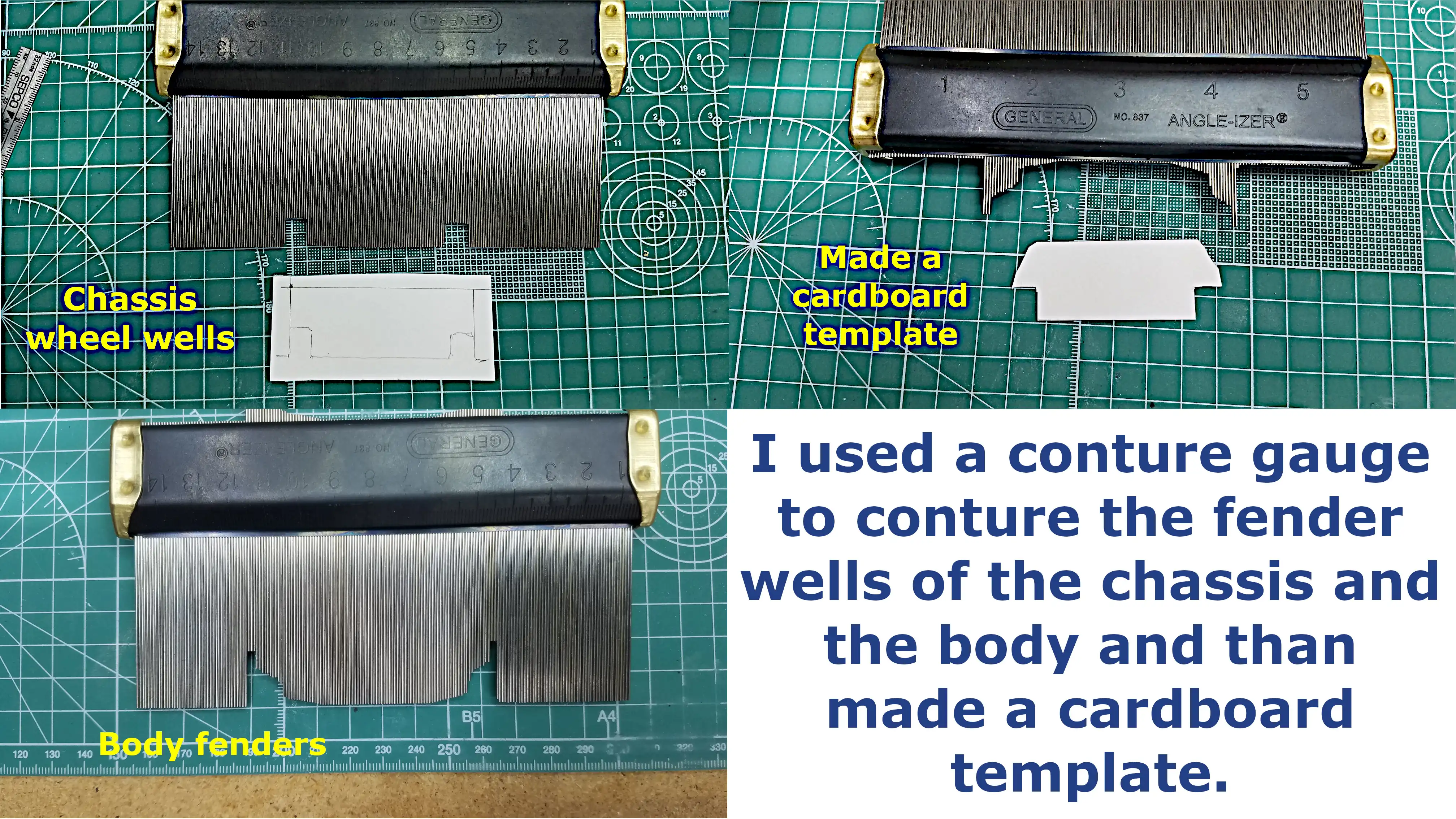 Scratch building the back wall of the trunk
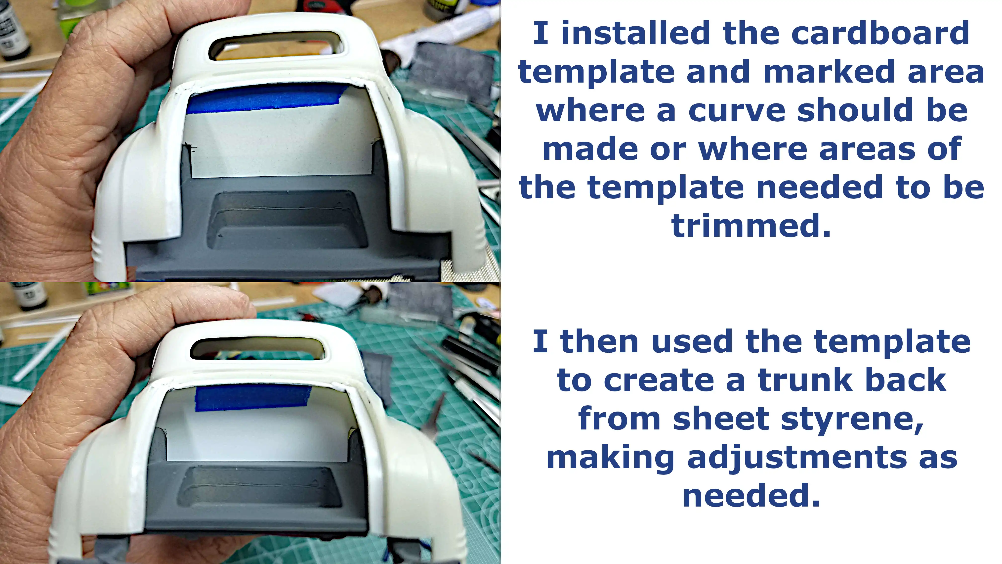 Testing the template of the back wall of the trunk
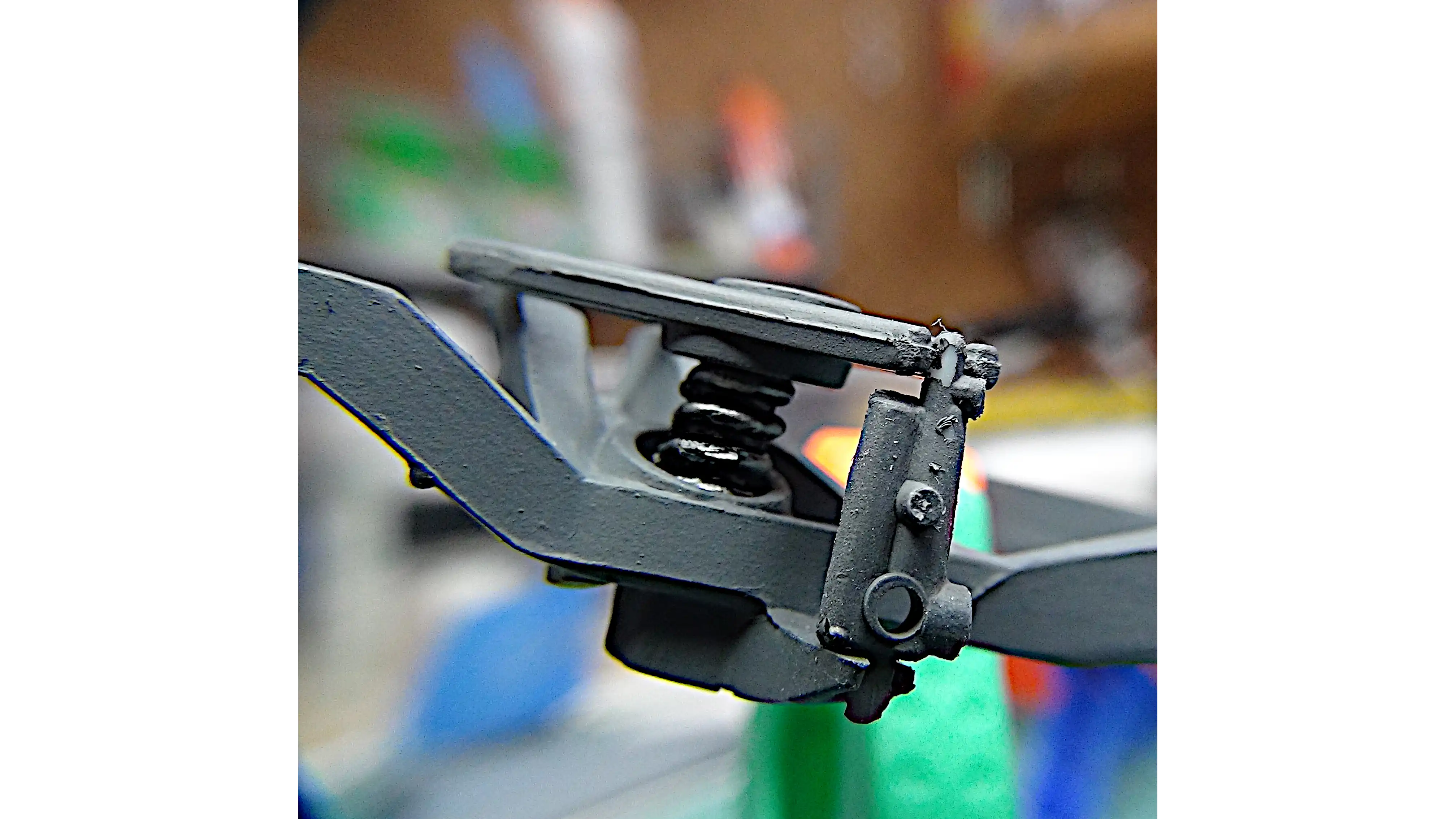
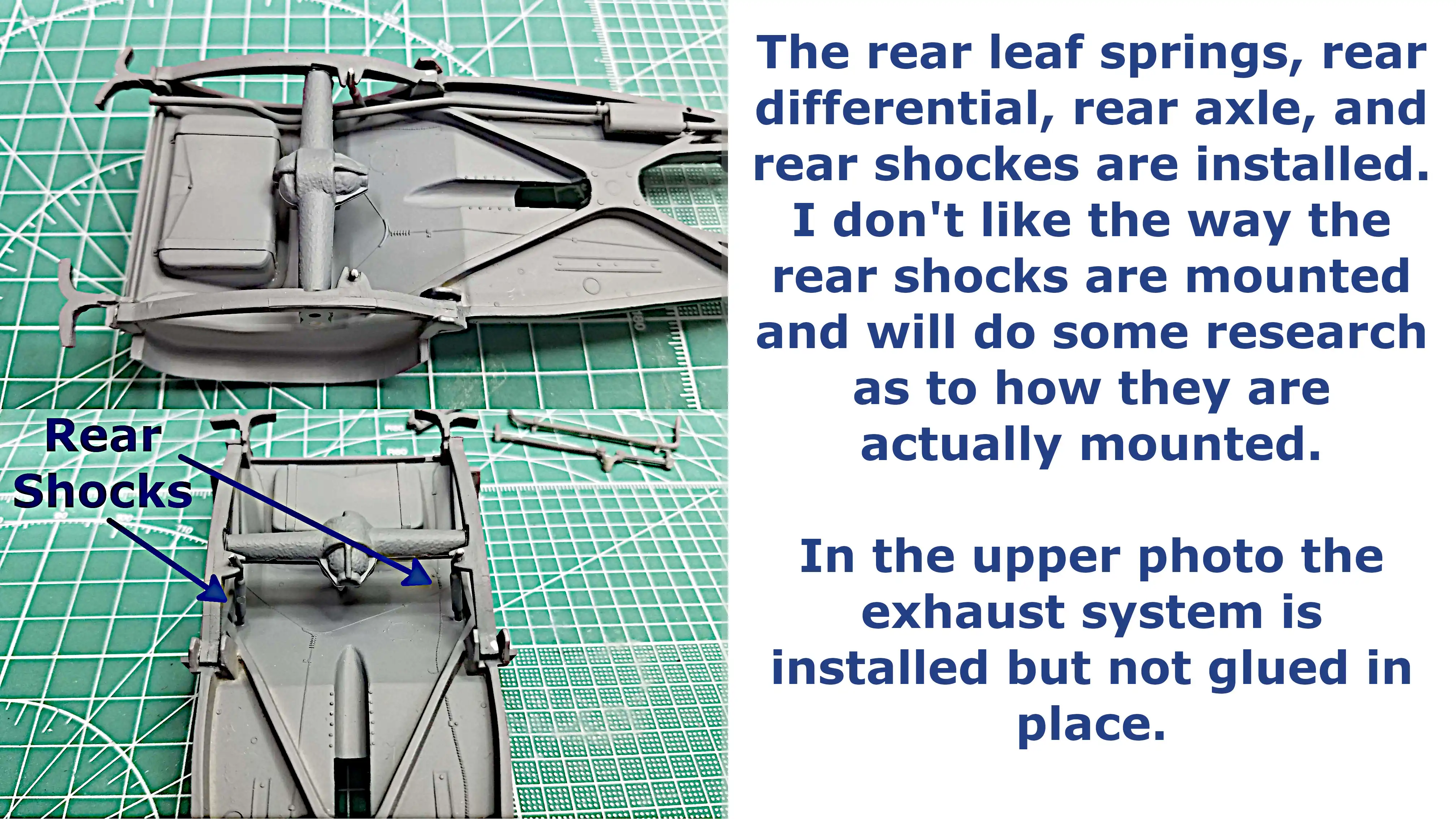 Rear leaf springs and shocks installed
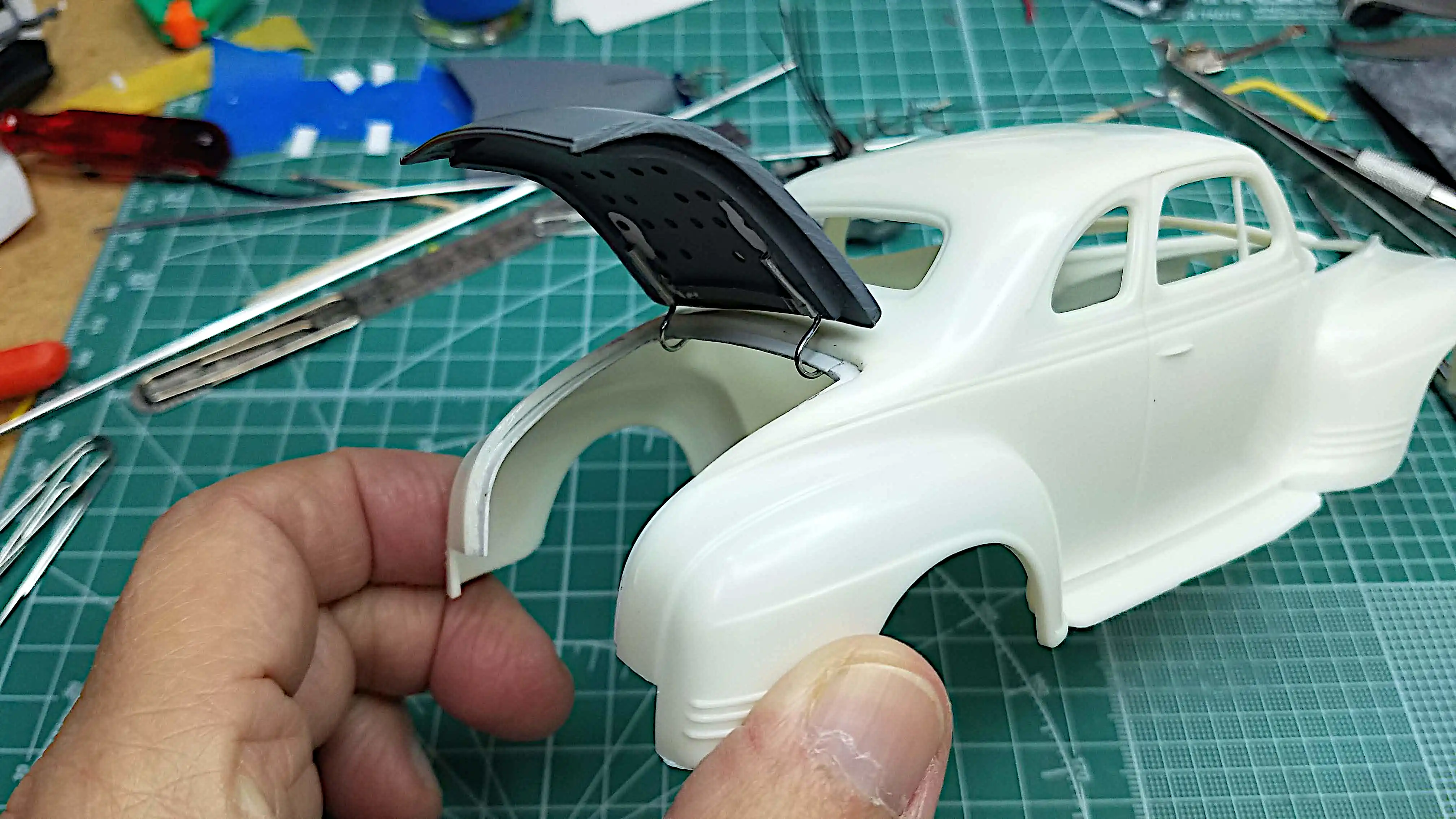
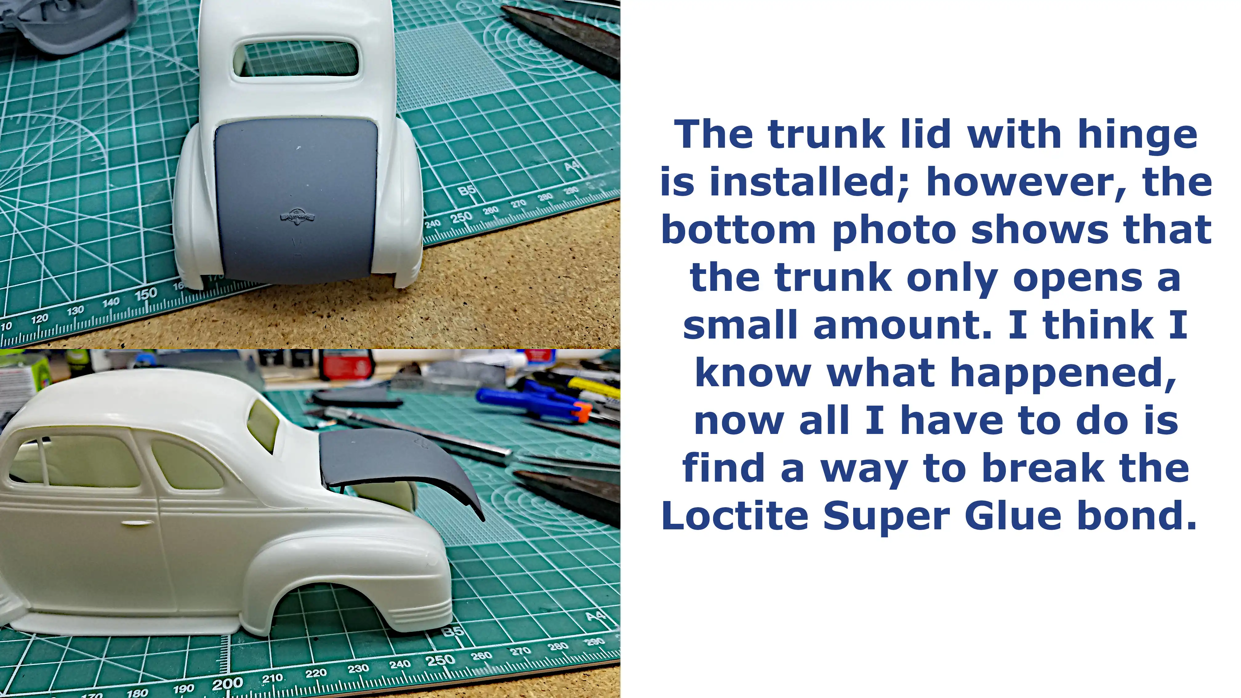 Trunk lid and hinge installed, but it's not right
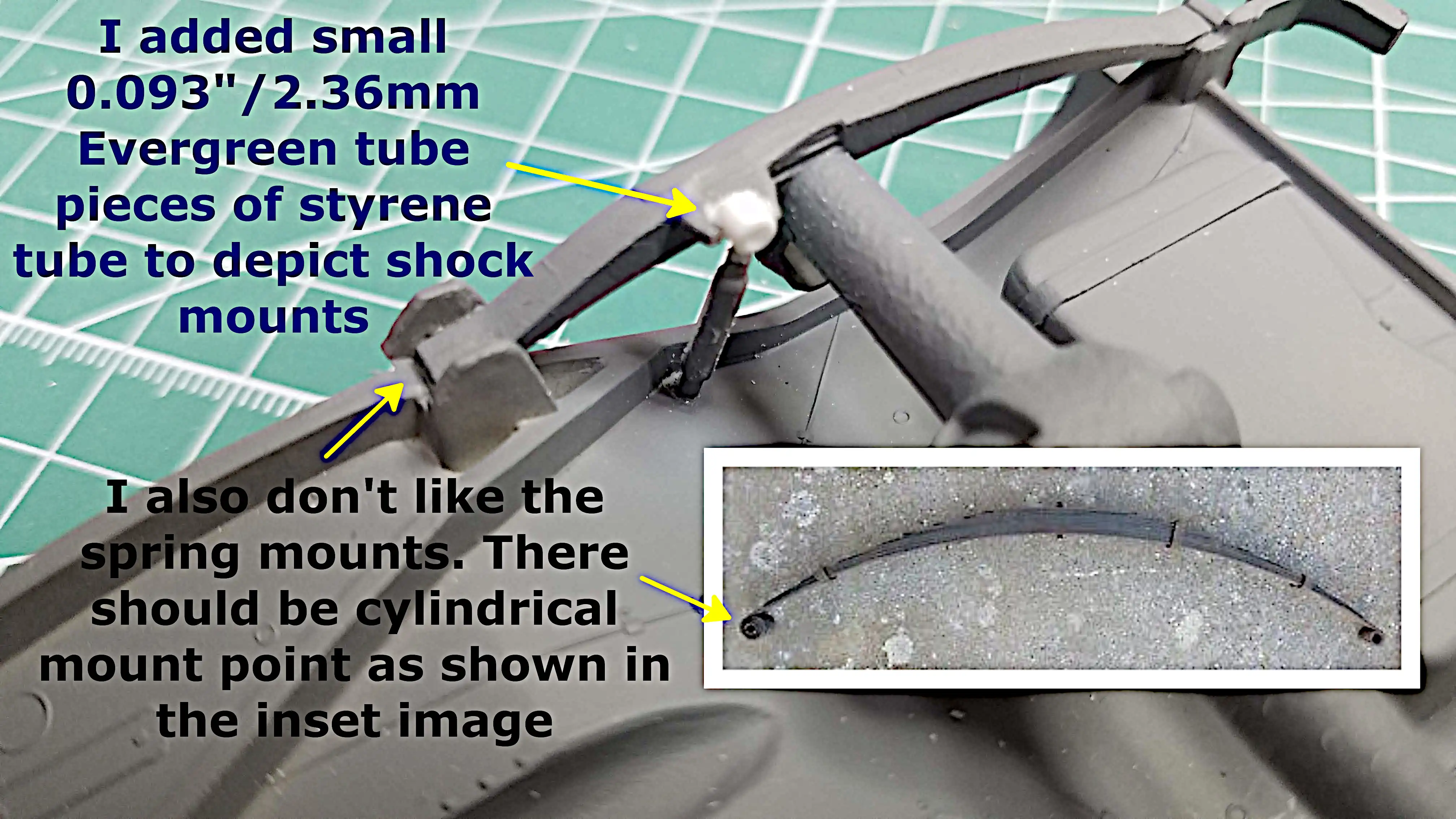 Modified rear shock mounts
 Modified rear shock mounts
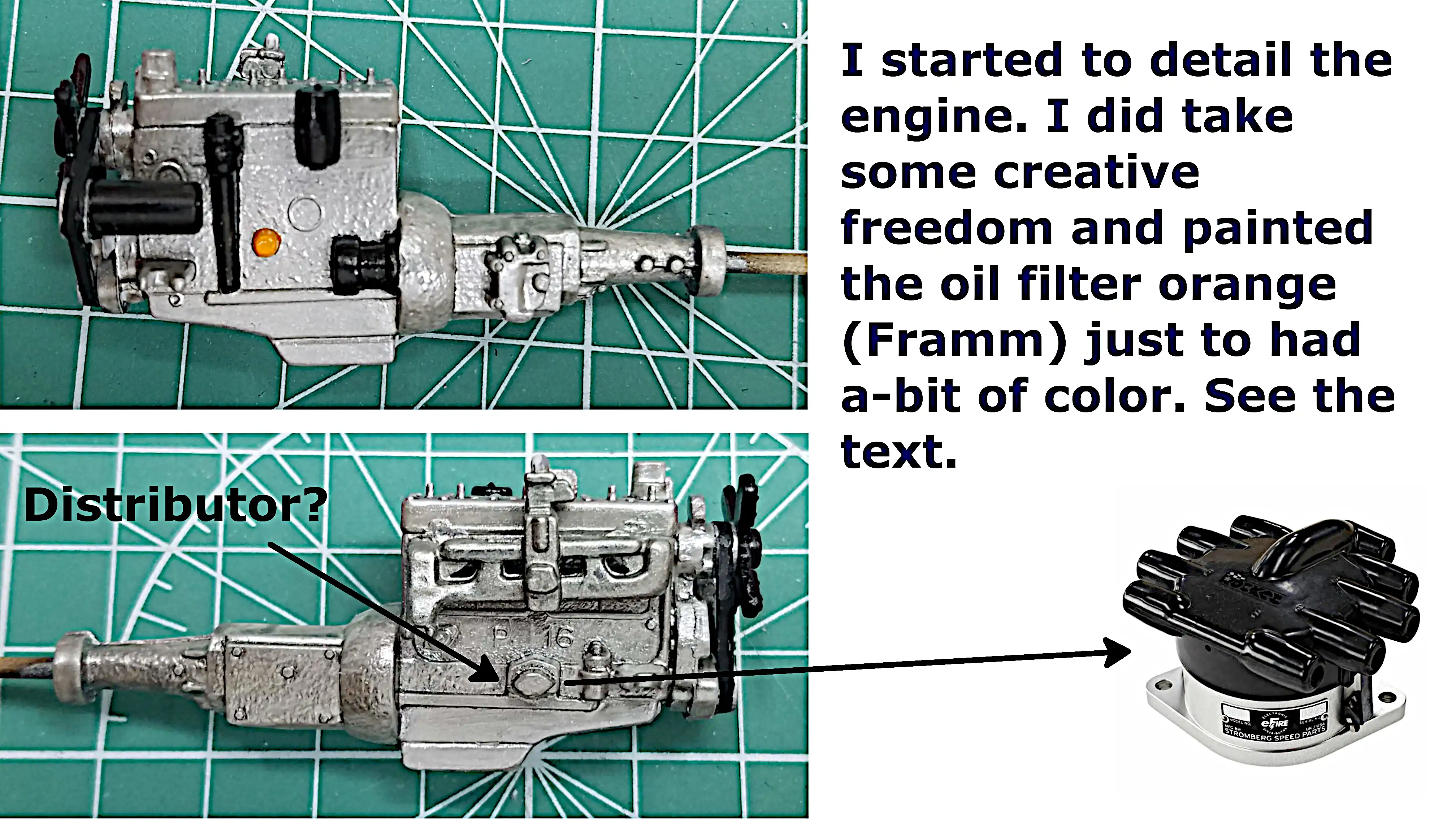 Detailing the engine
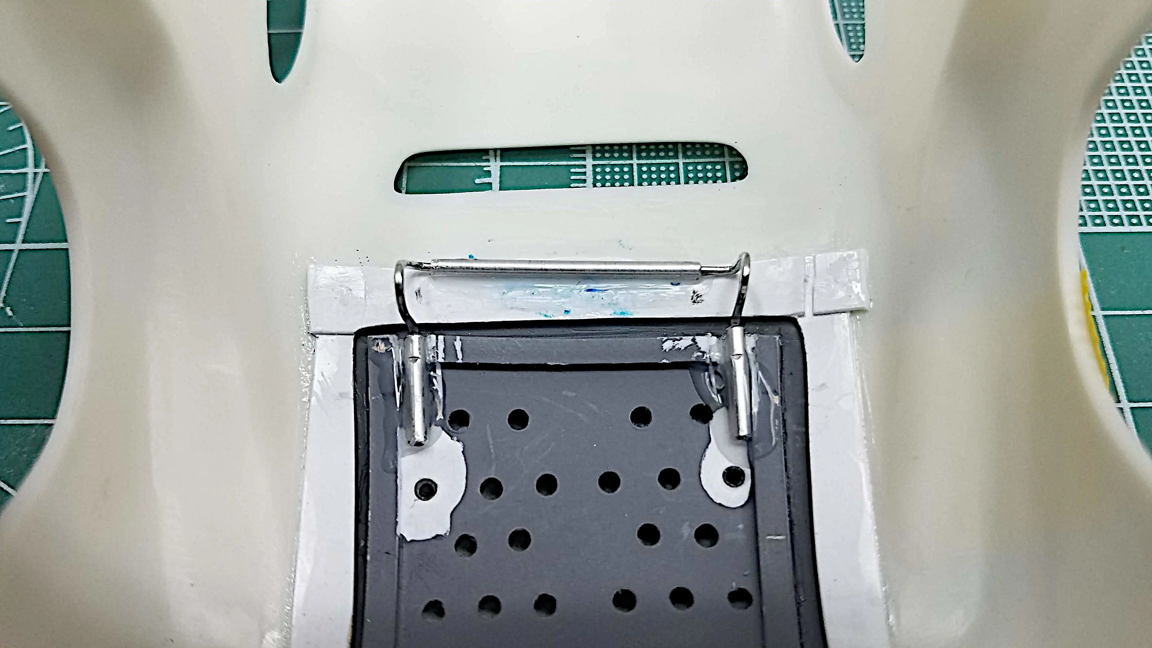 New trunk lid hinge installed
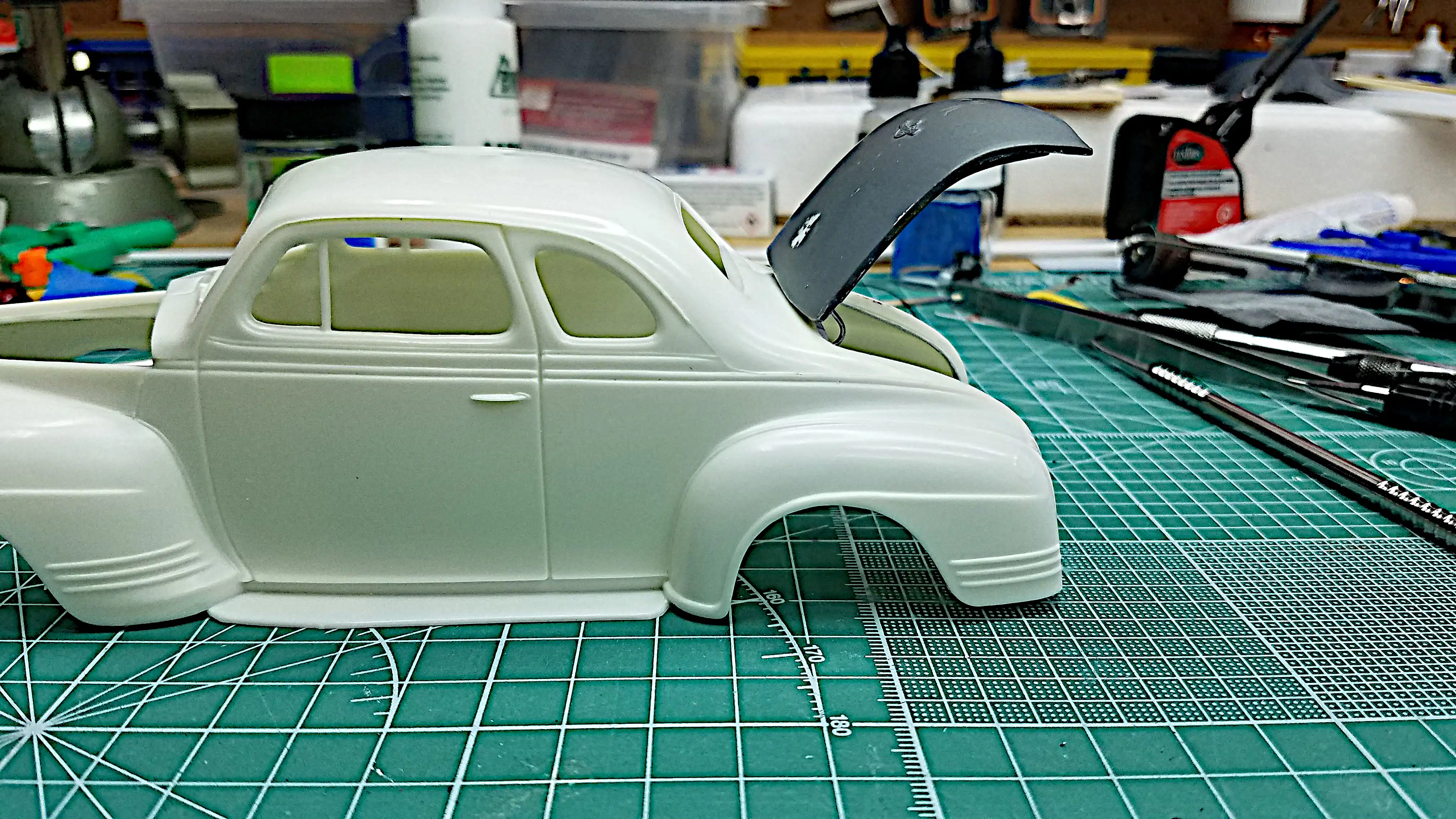
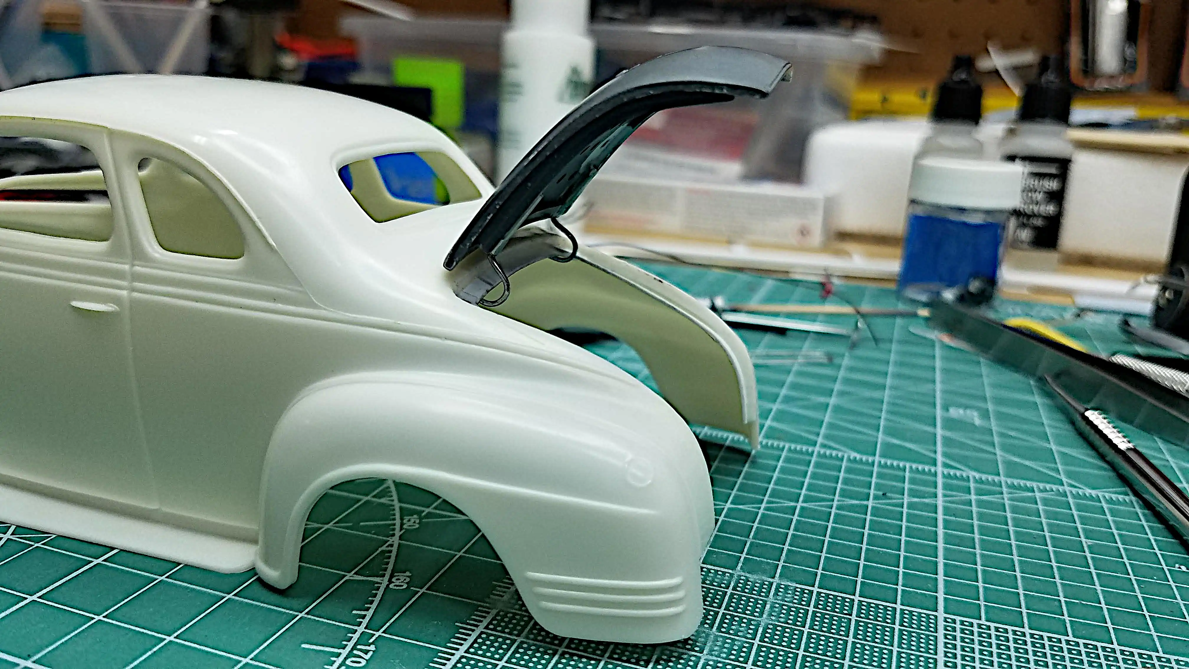
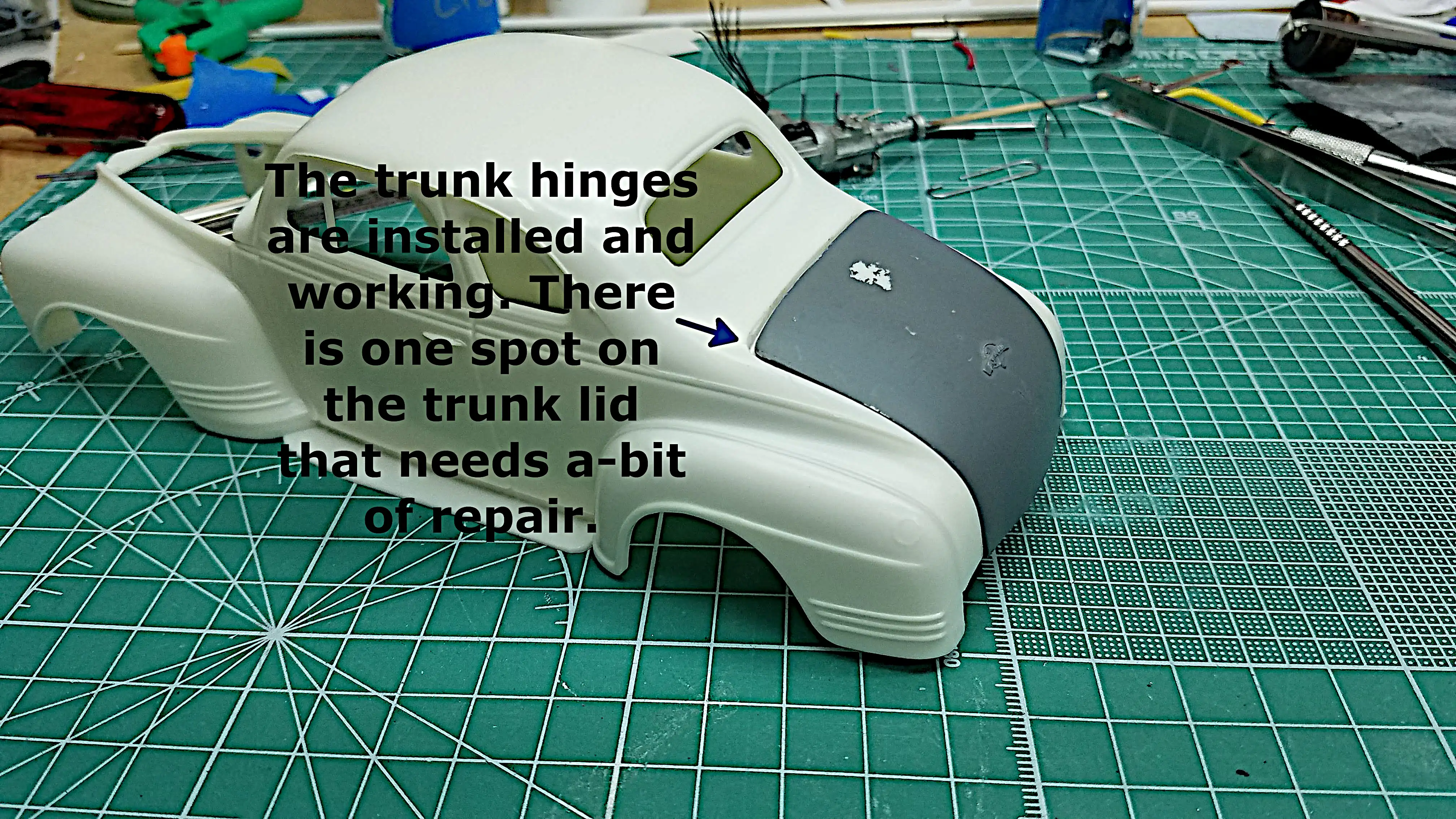 New trunk lid hinges are installed and working
 New trunk lid hinges are installed and working
 New trunk lid hinges are installed and working
 New trunk lid hinges are installed and working
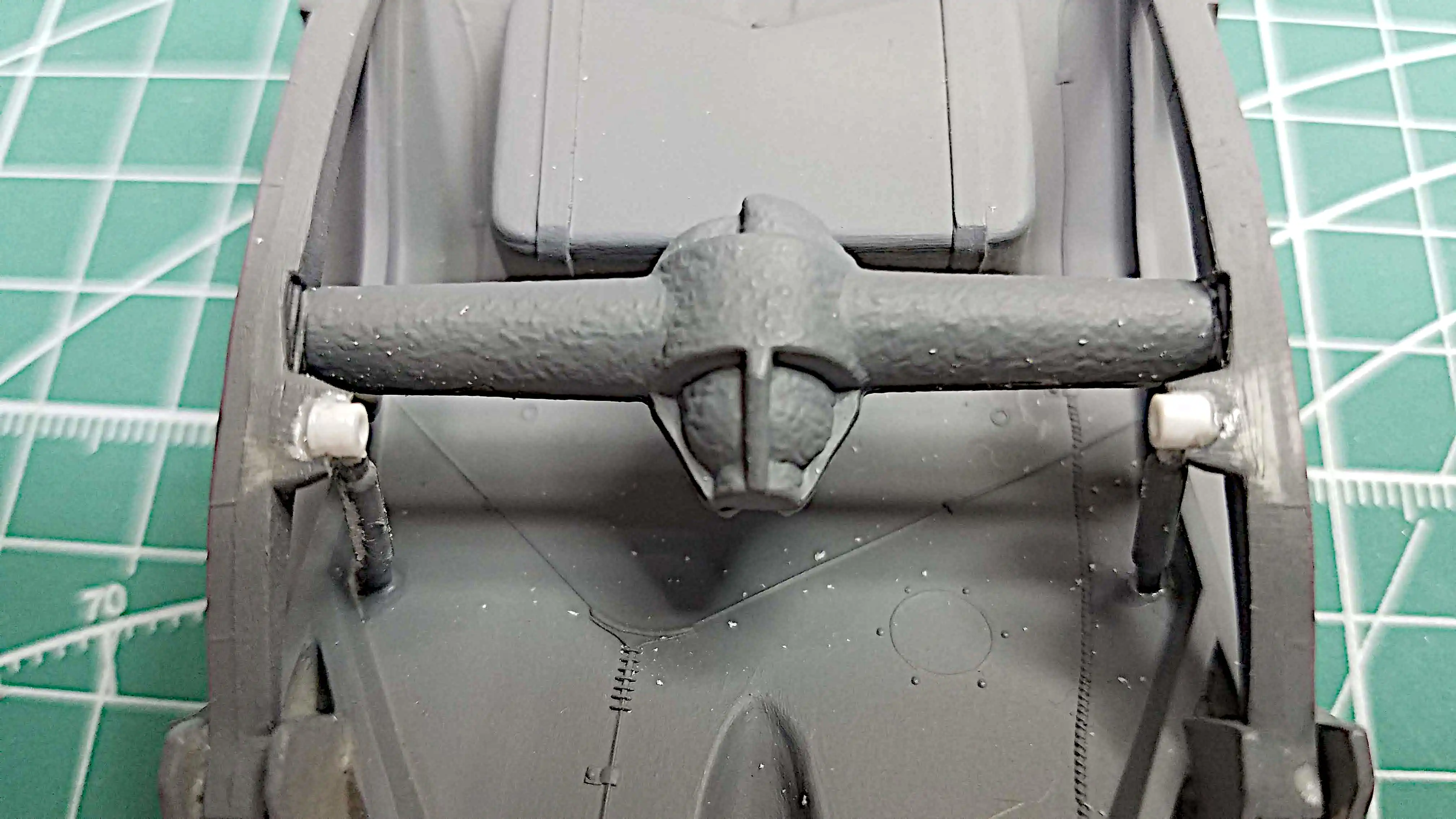
 Dry fitting lower A-Frame, coil spring and Spindle
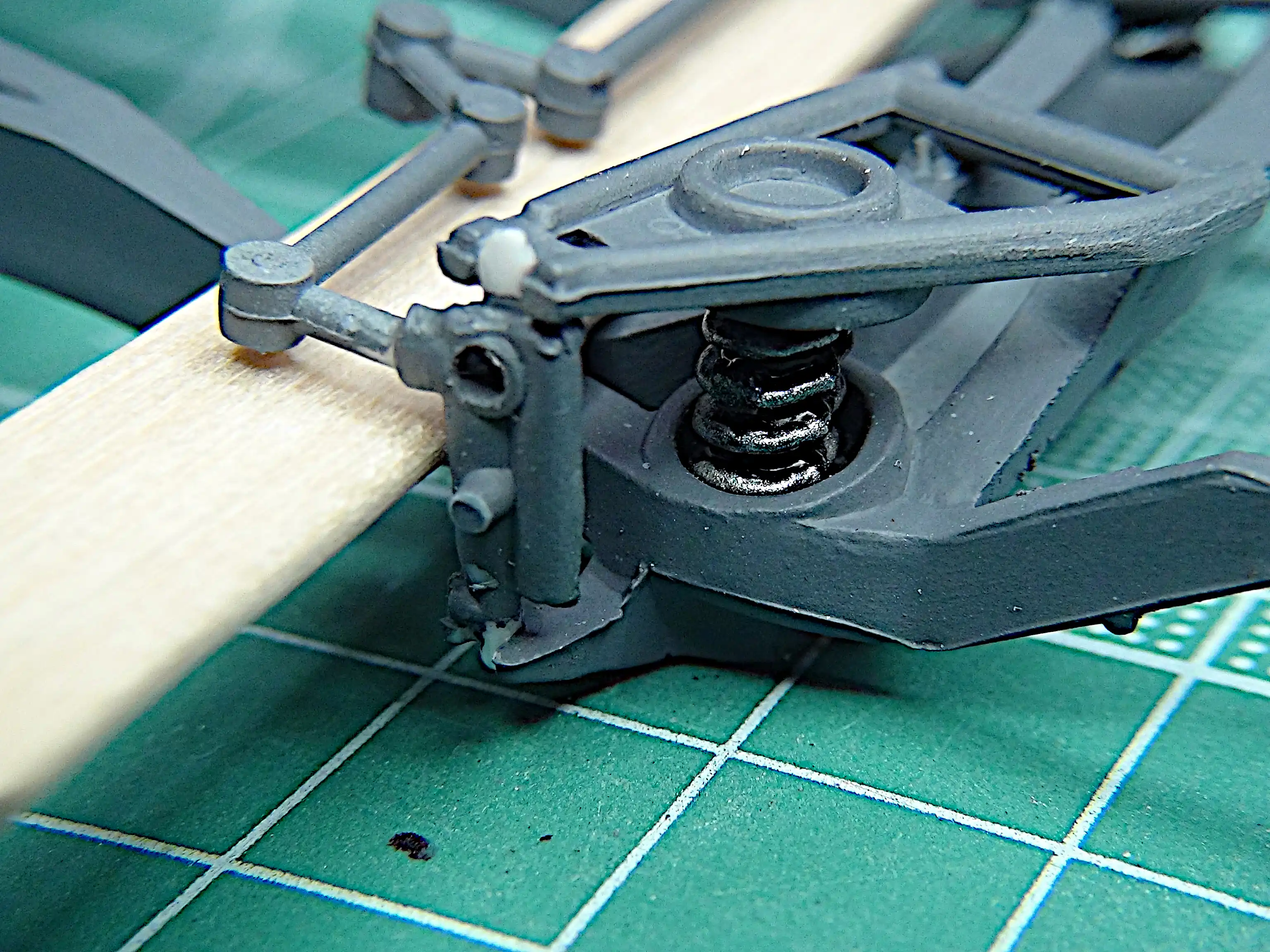 Tie rod is added and being held in place
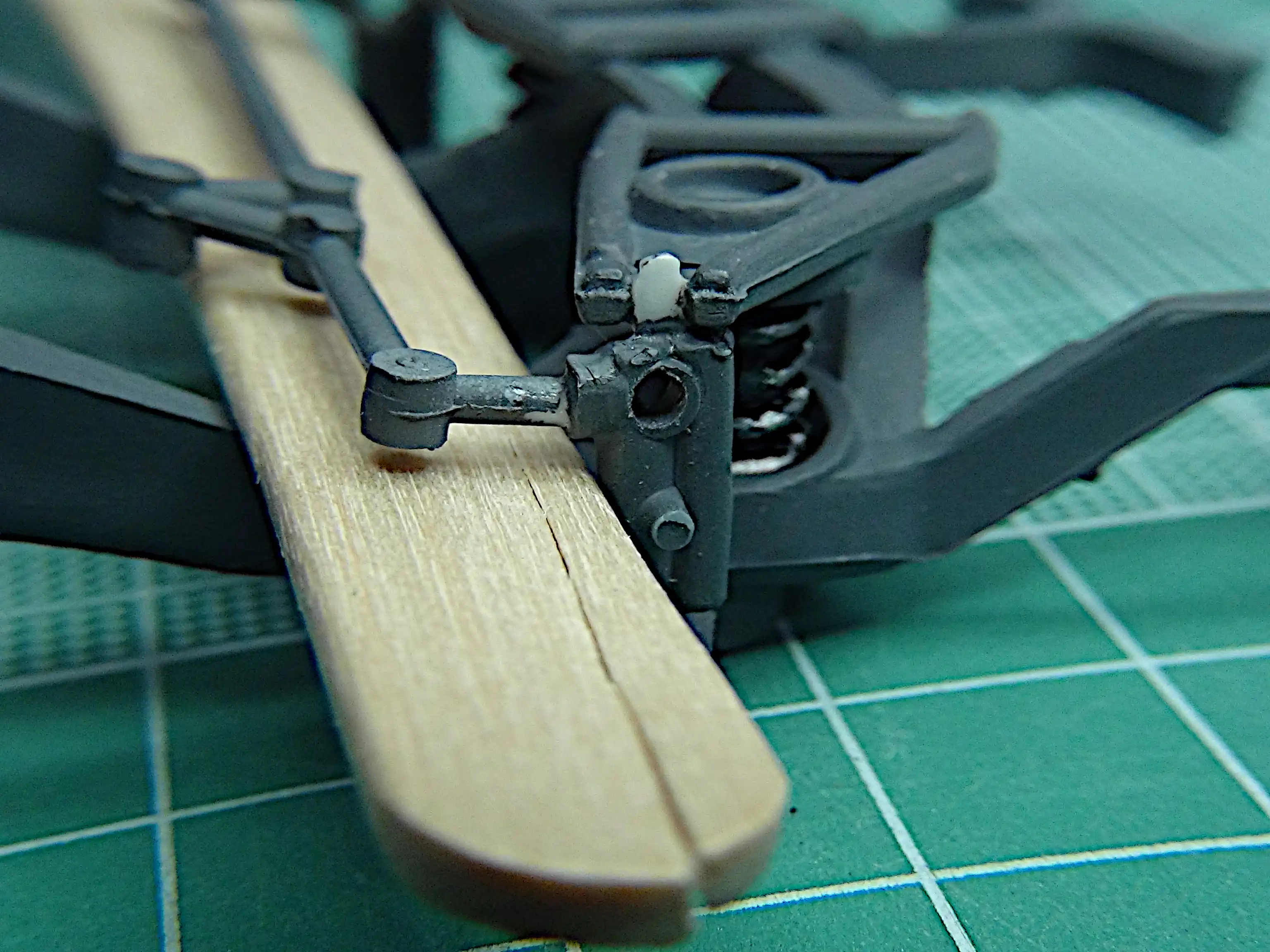 Tamiya fast setting glue applied
 Front inner wheels are installed
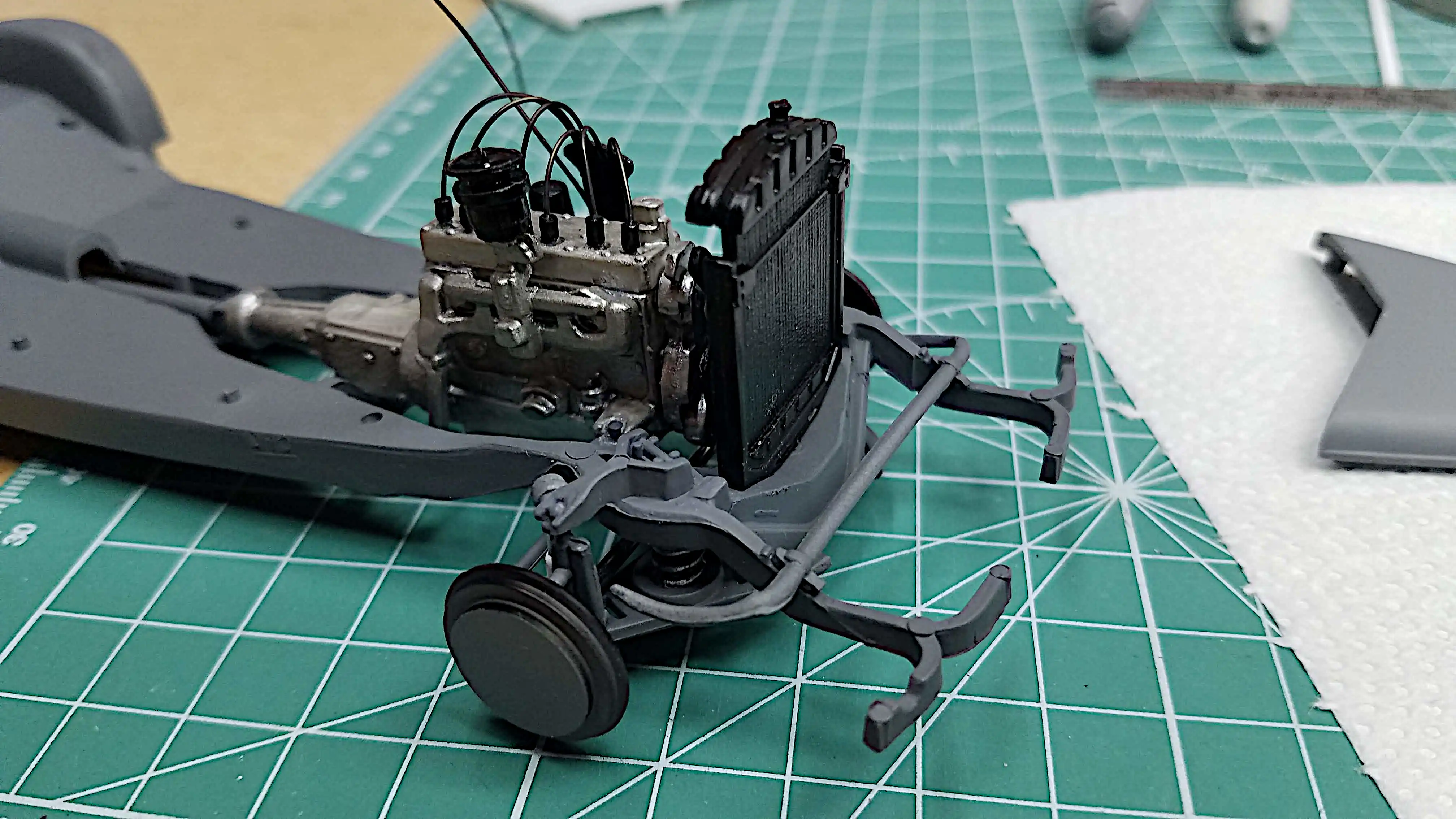
 This photo highlights the front suspension
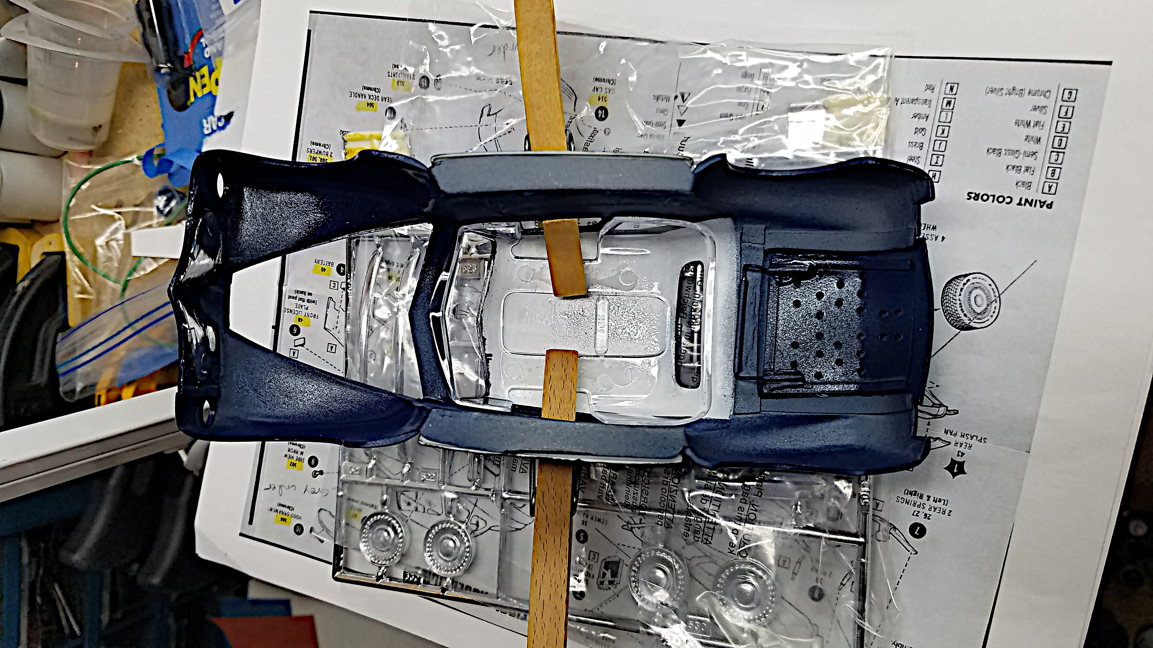
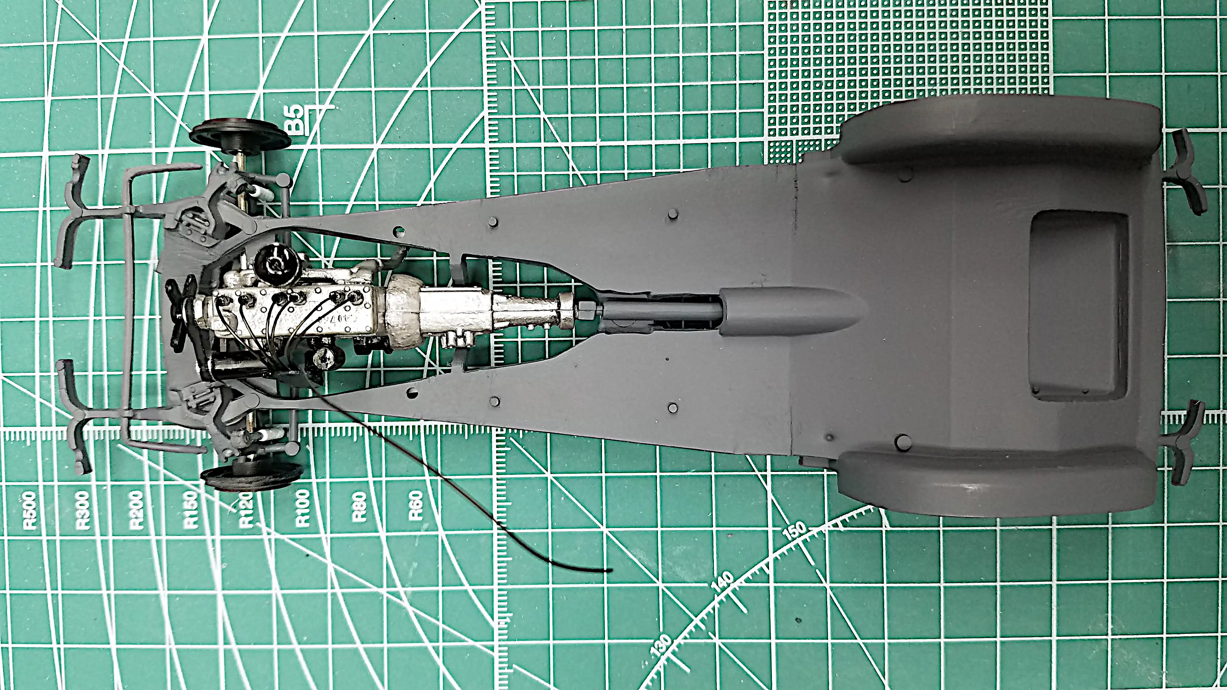 Another view of chassis with engine and front suspension
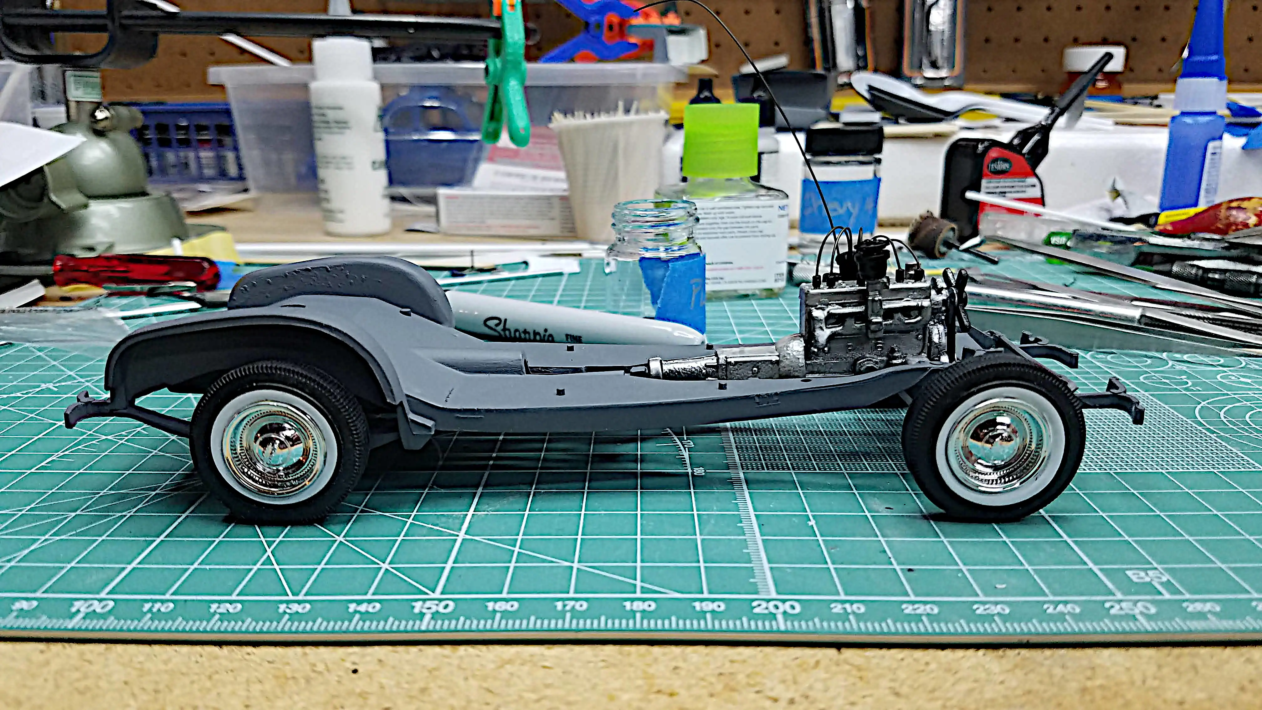 Checking the stance
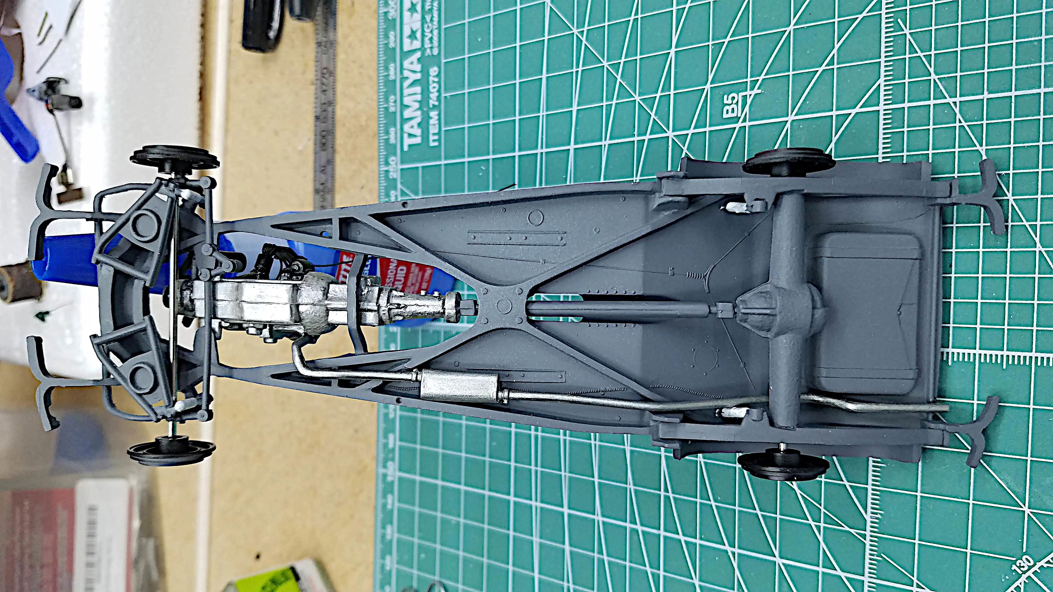
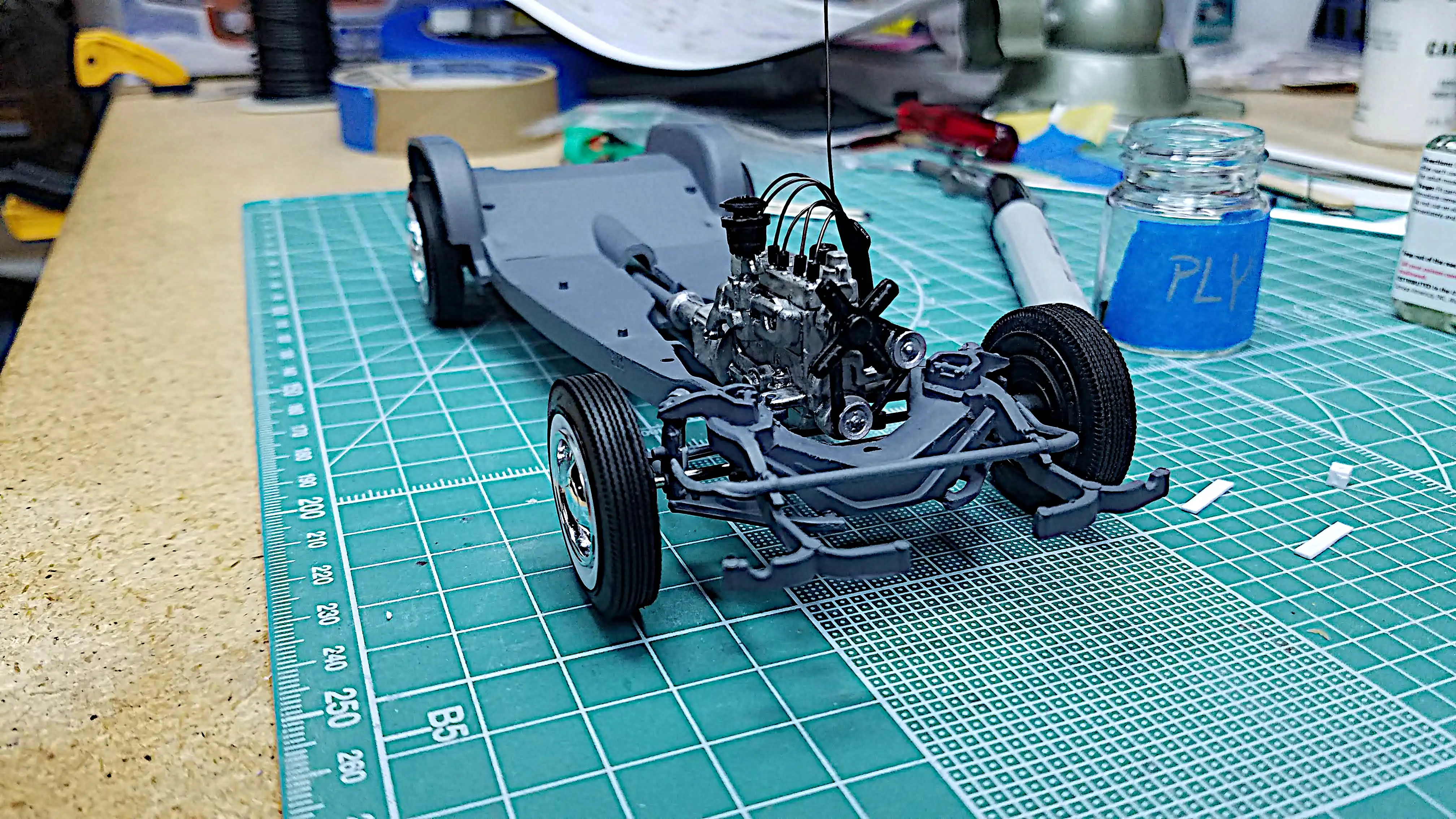 Another view of the chassis from the front right
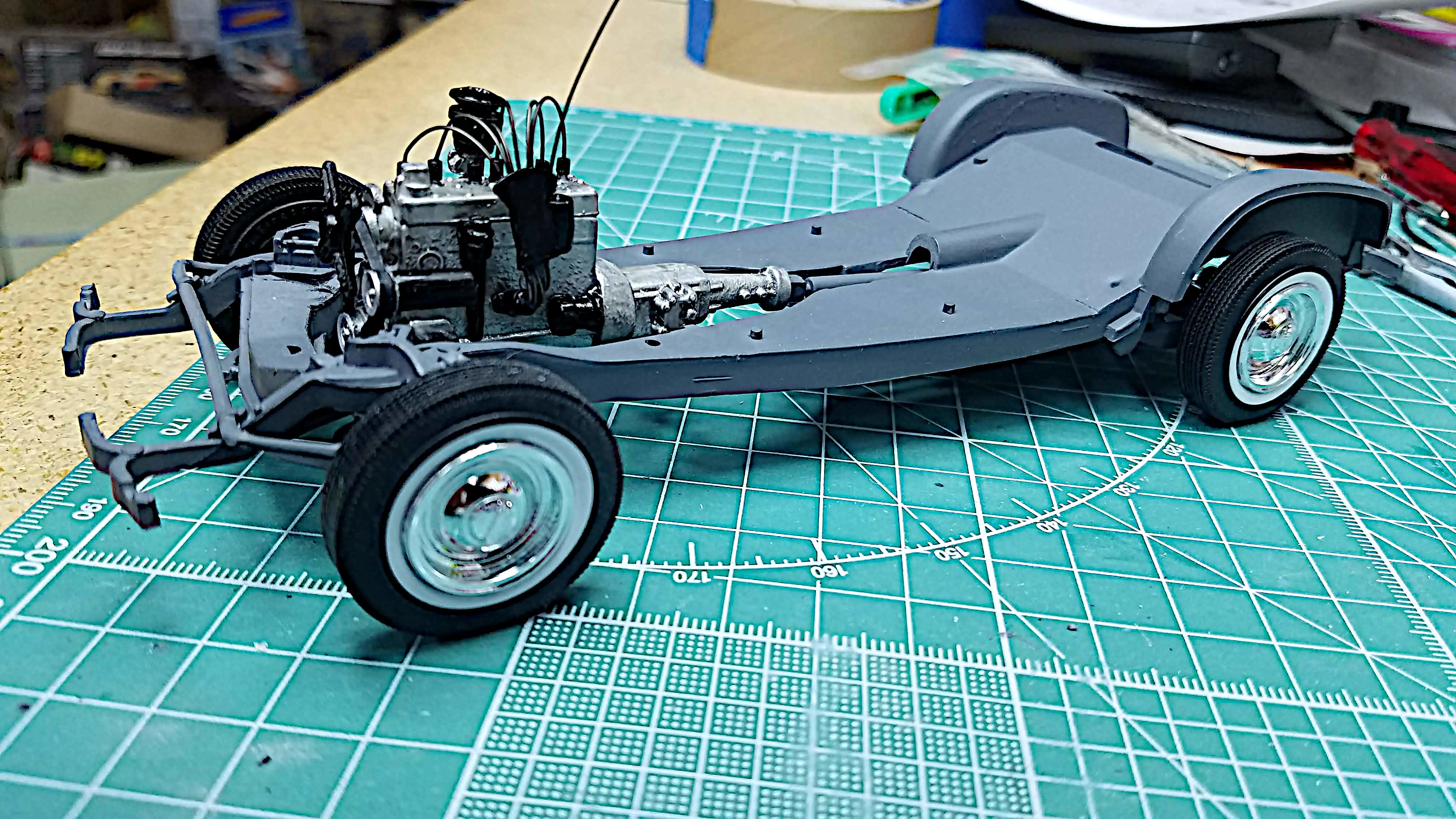 Another view of the chassis from the front left
 The front body panel is inserted
 Working on the interior tub
 Working on the firewall
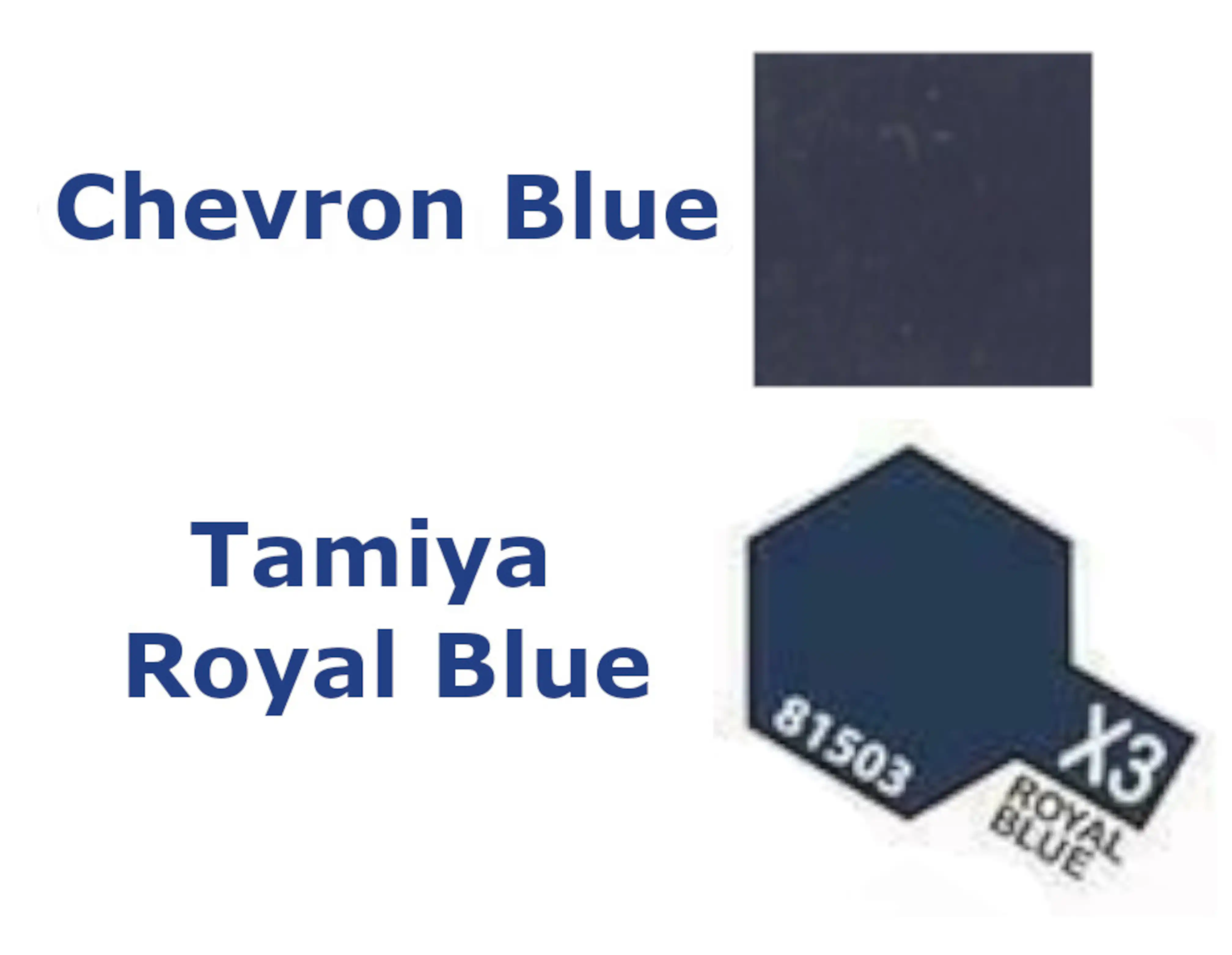 Body color chips
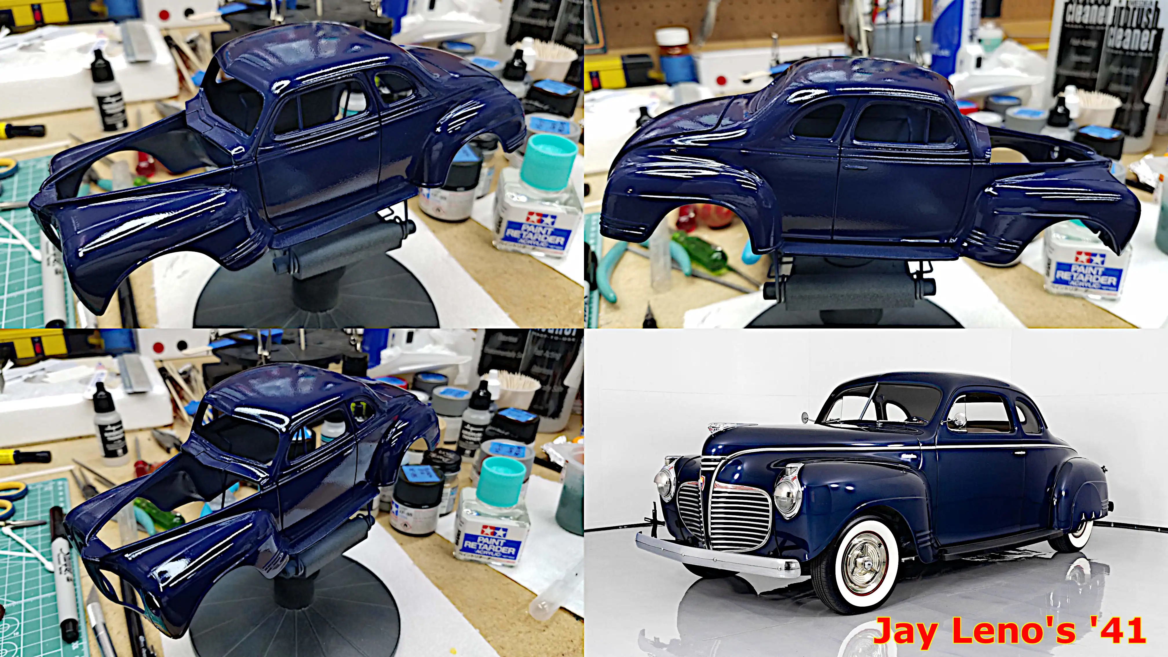 The body has been painted
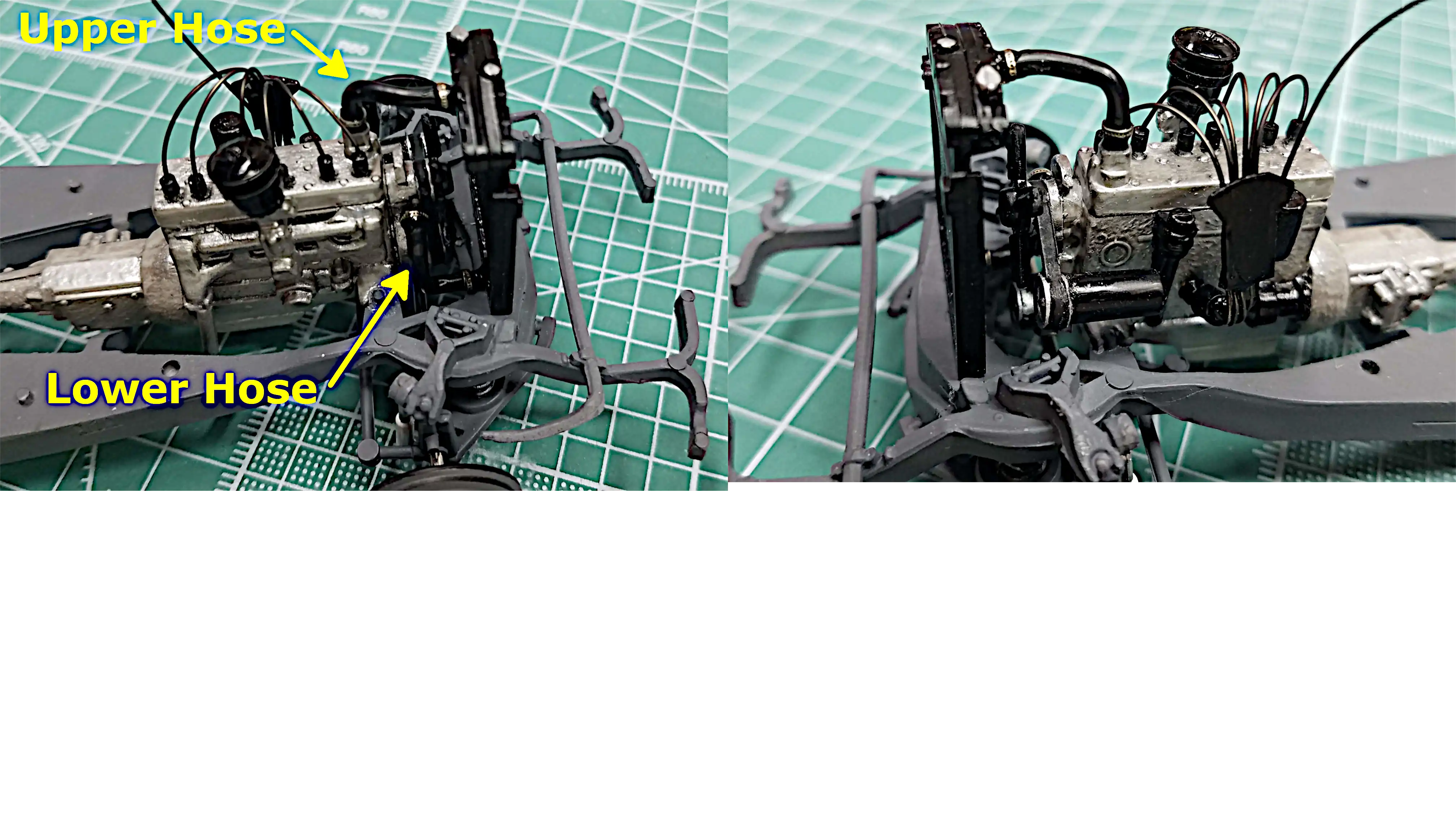 Radiator hoses and clamps installed
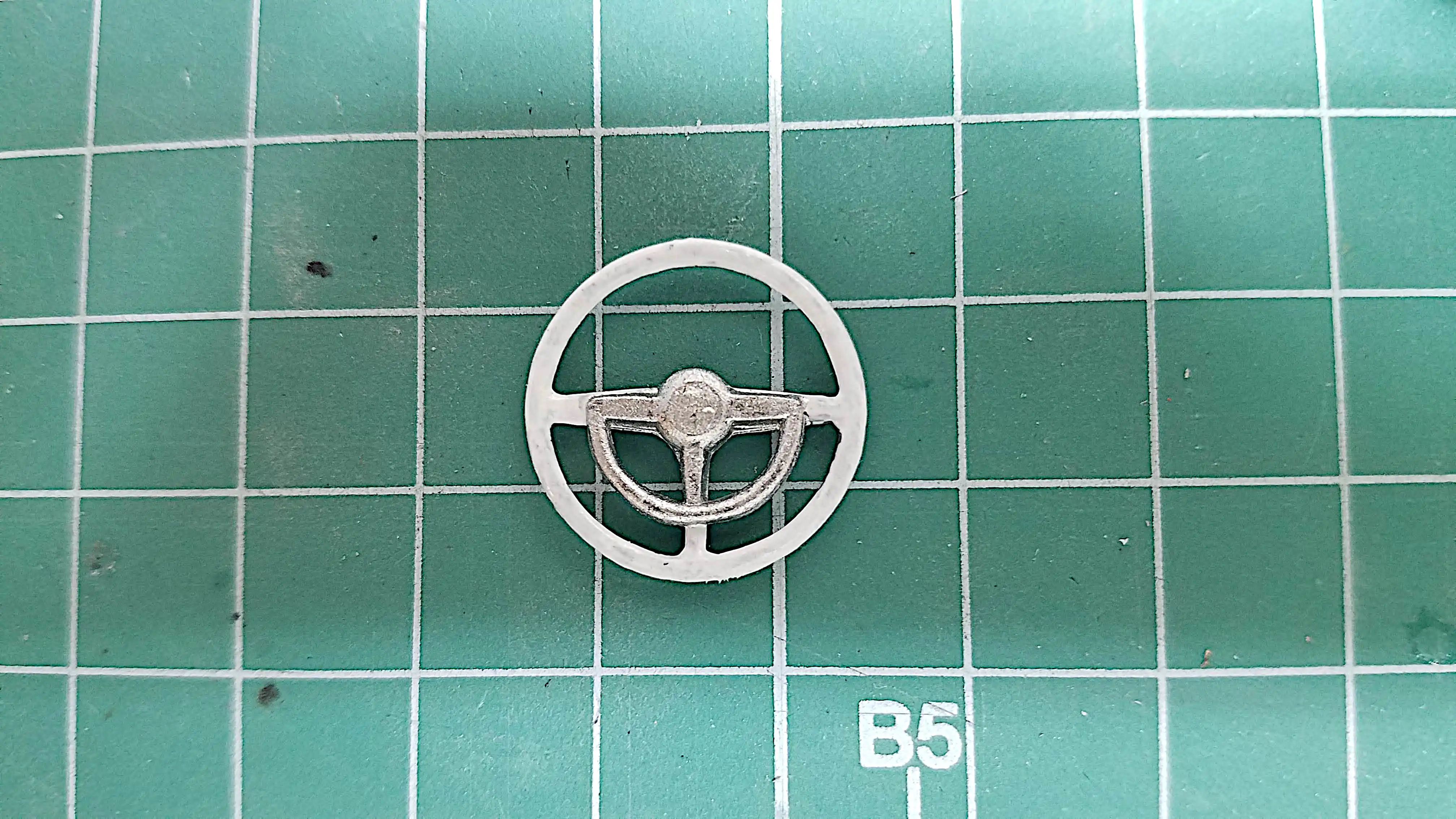 Steering wheel painted
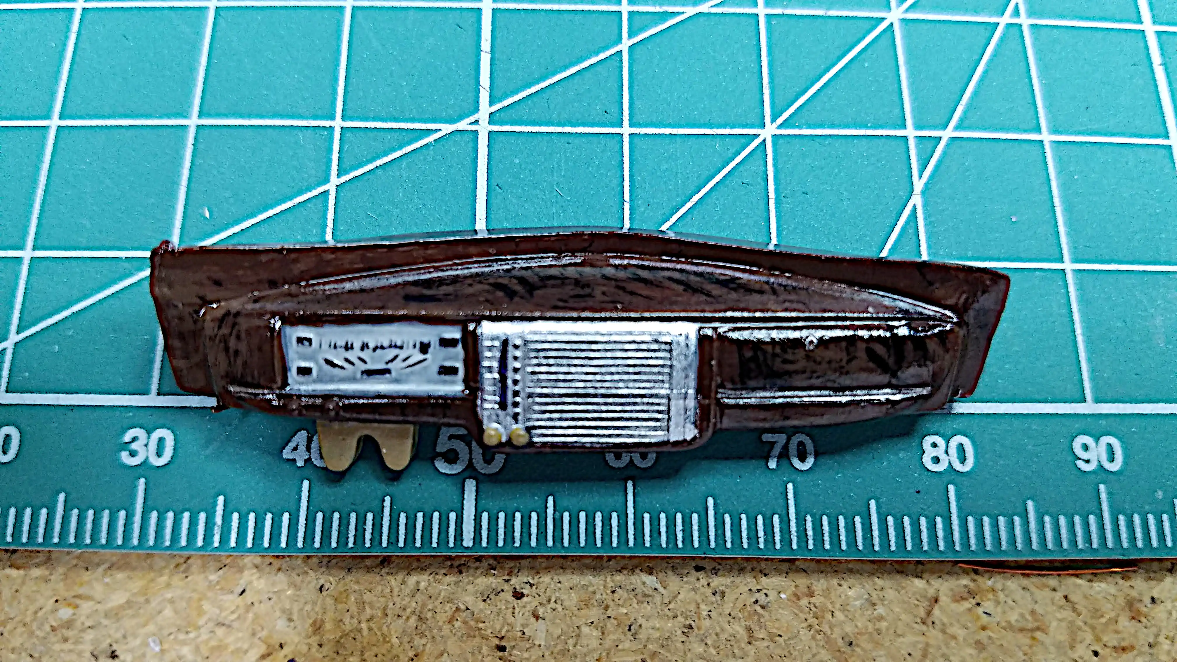 Detailed dashboard
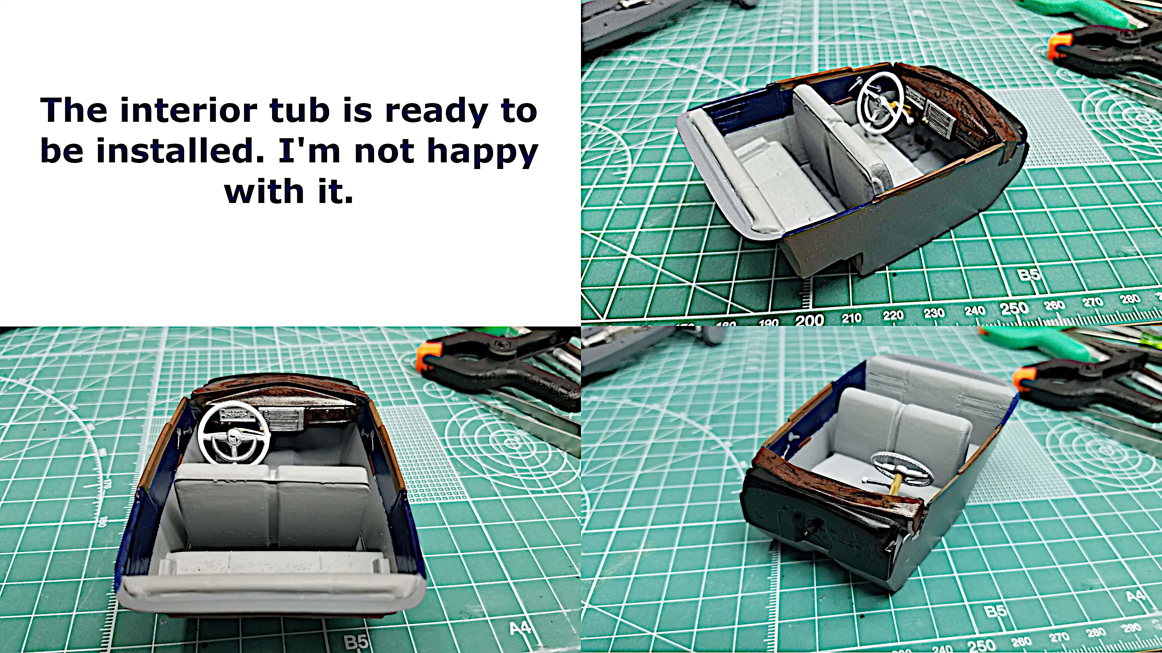 Interior tub is ready to be installed
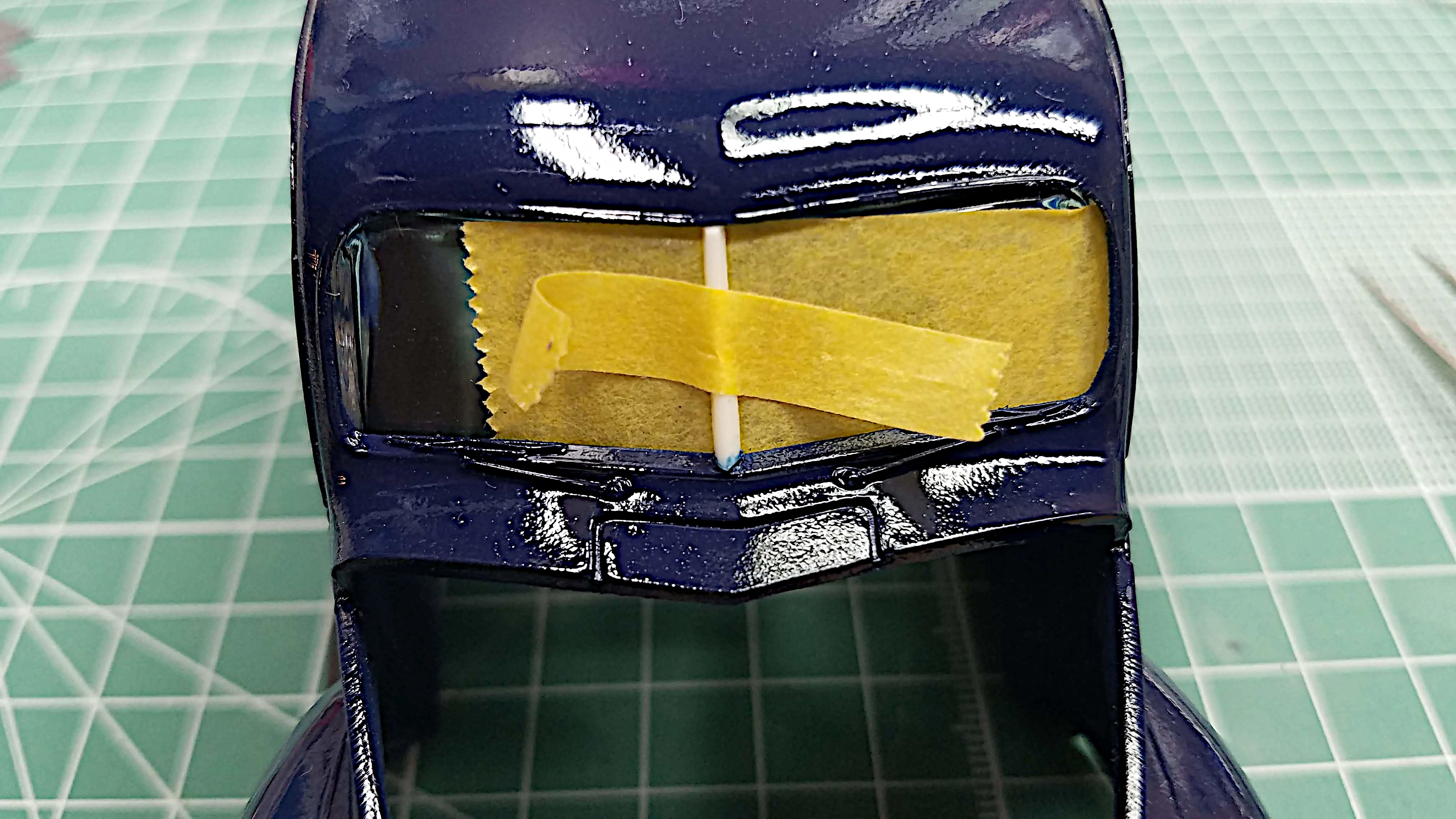 Installing the windshield center post
 windshield center post fell off; re-attached
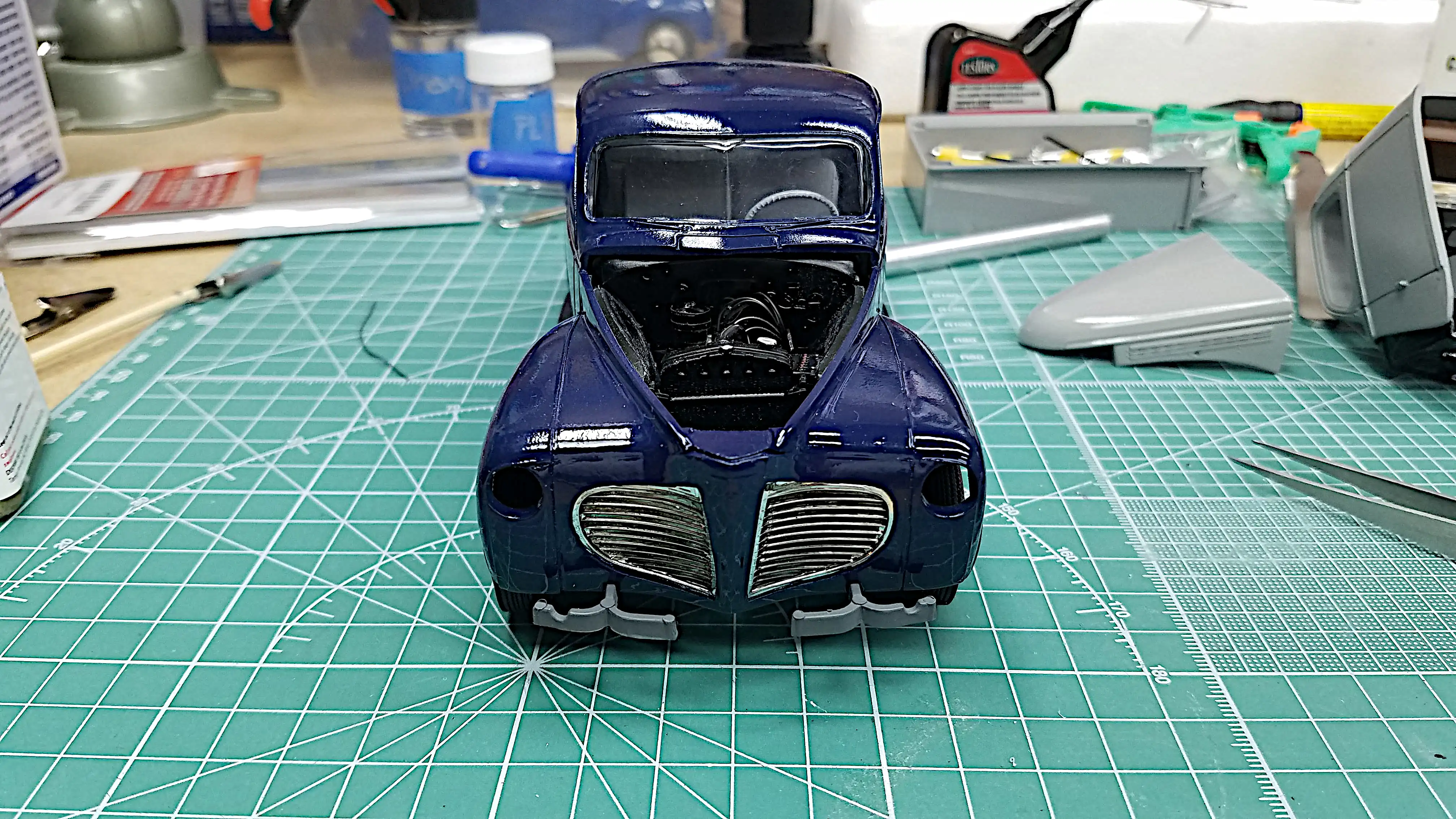 Front view taken before windshield divider is installed
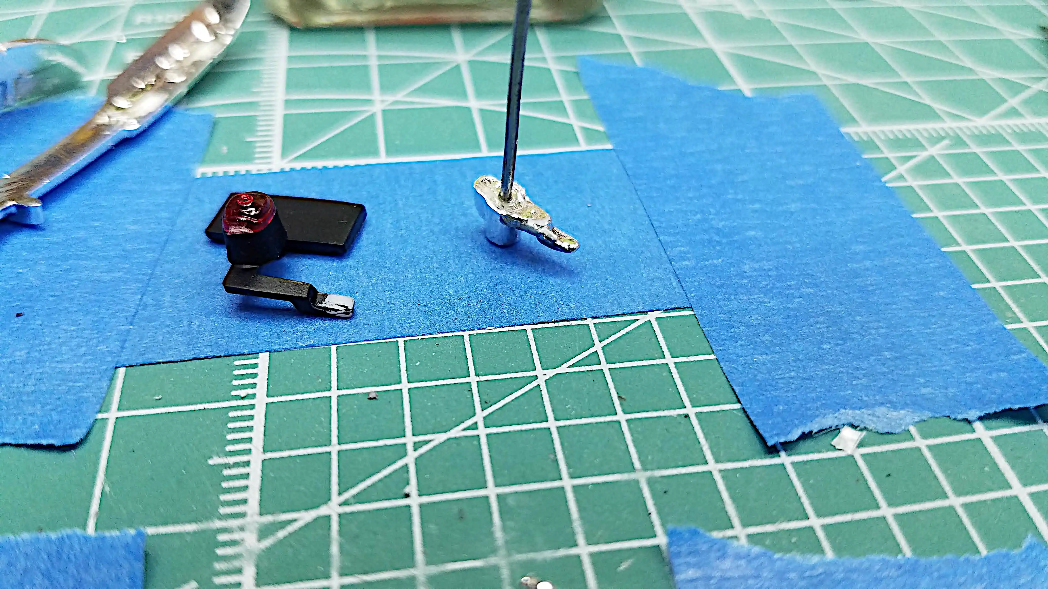 Adding pins to mount some small pieces
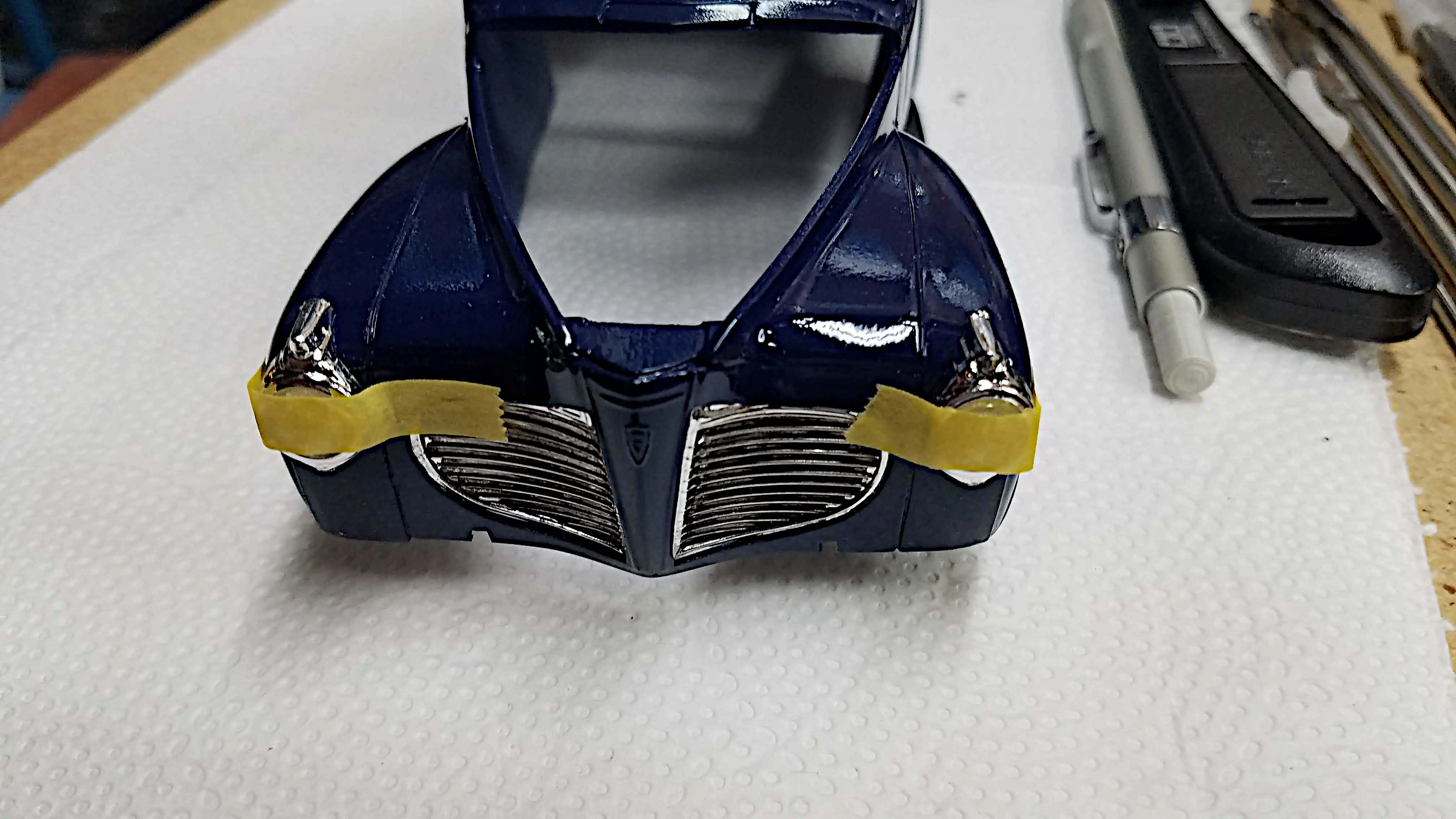 Headlights are glued in place
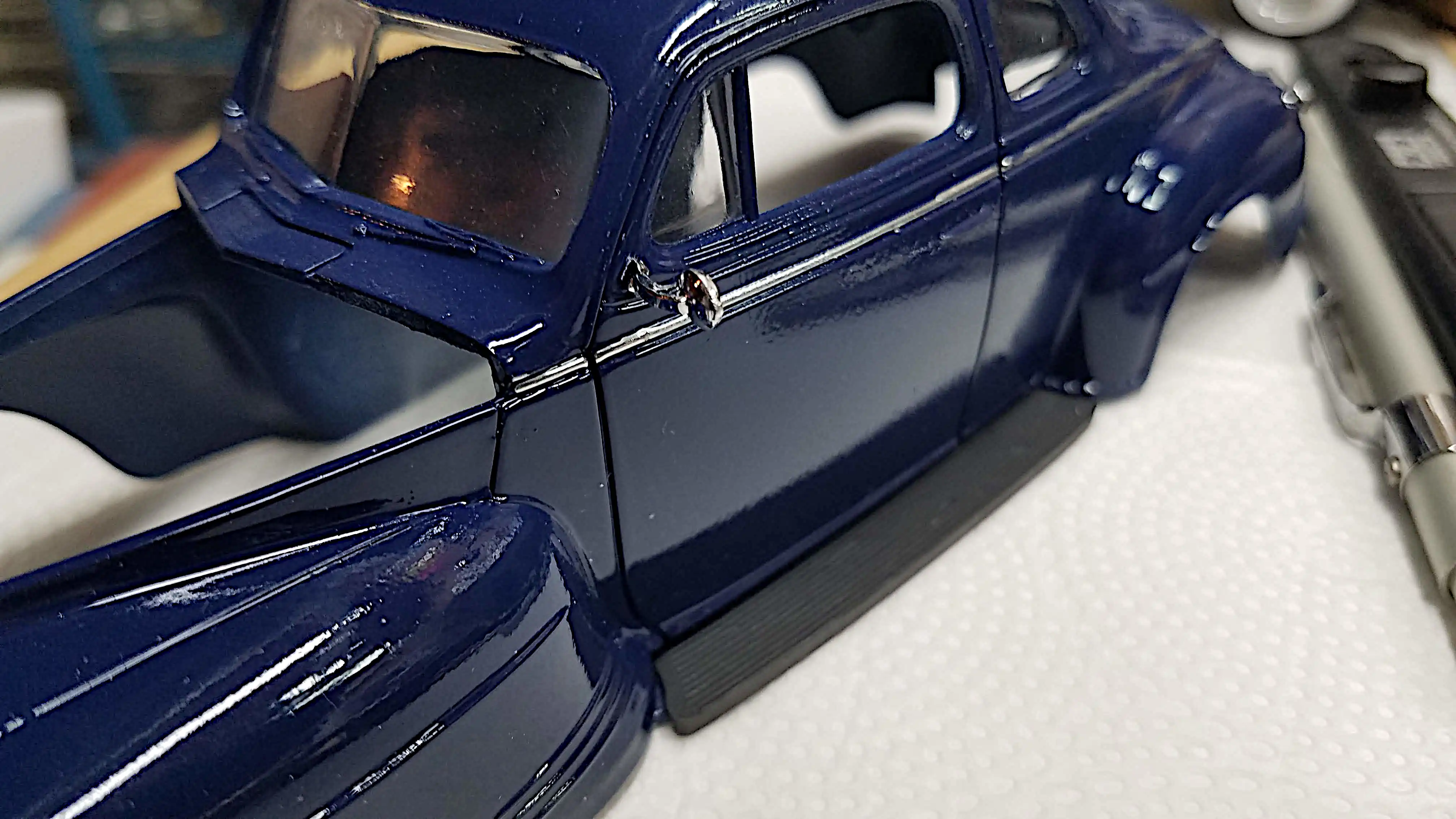 Driver side mirror installed
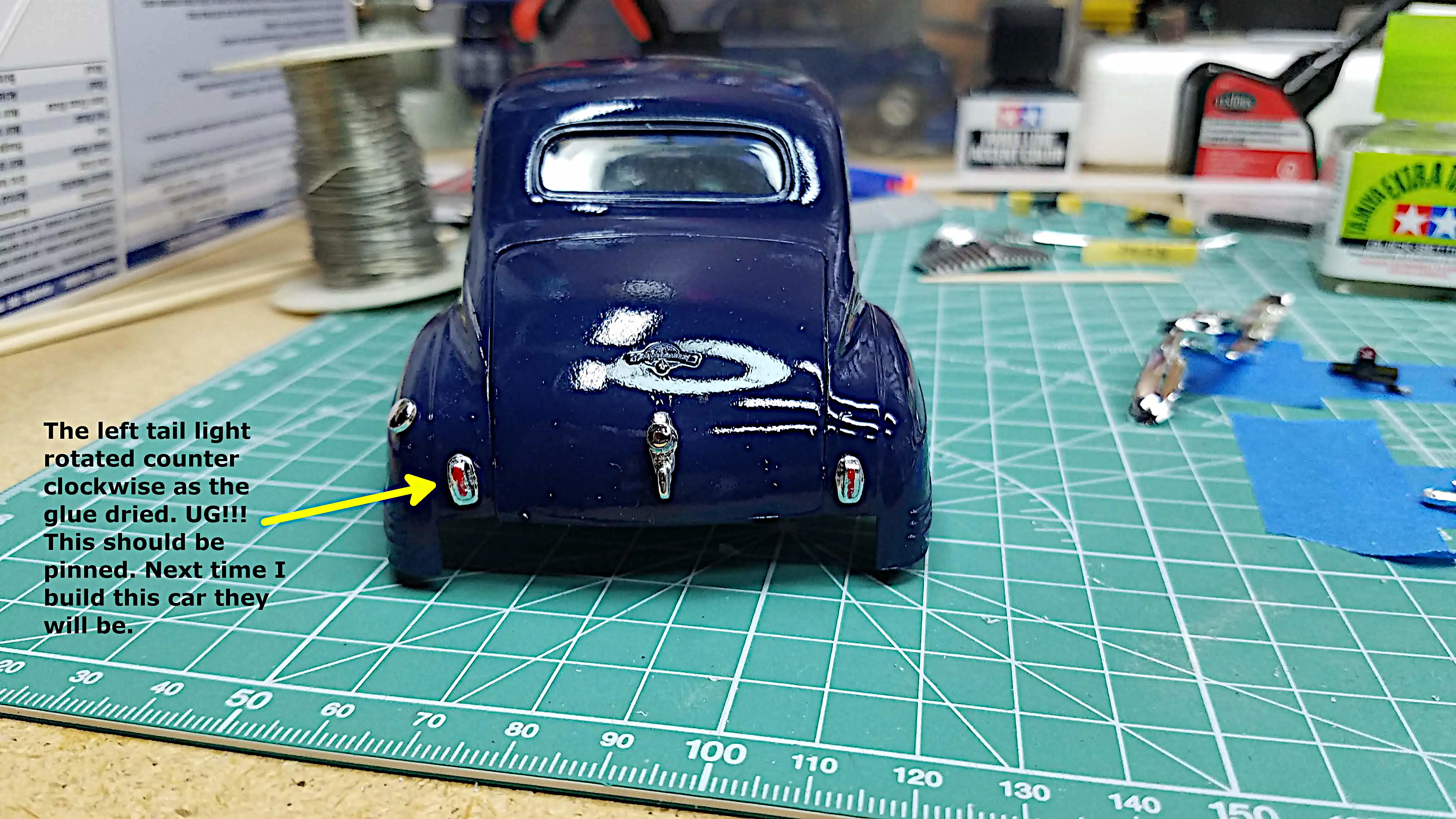 Left tail light rotated while glue was drying
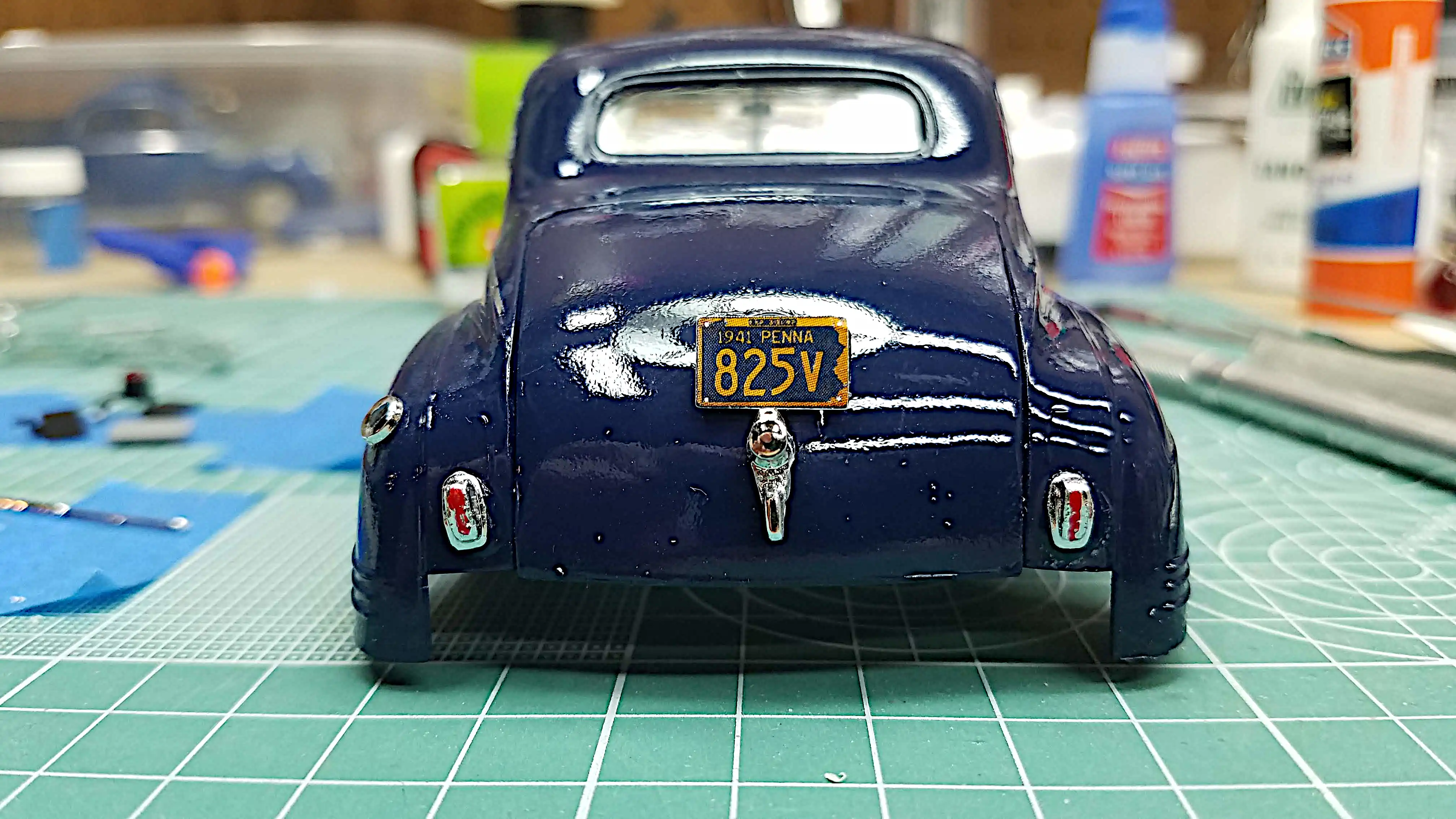 Printed my own license plate
 The 1941 Plymouth Coupe is finished
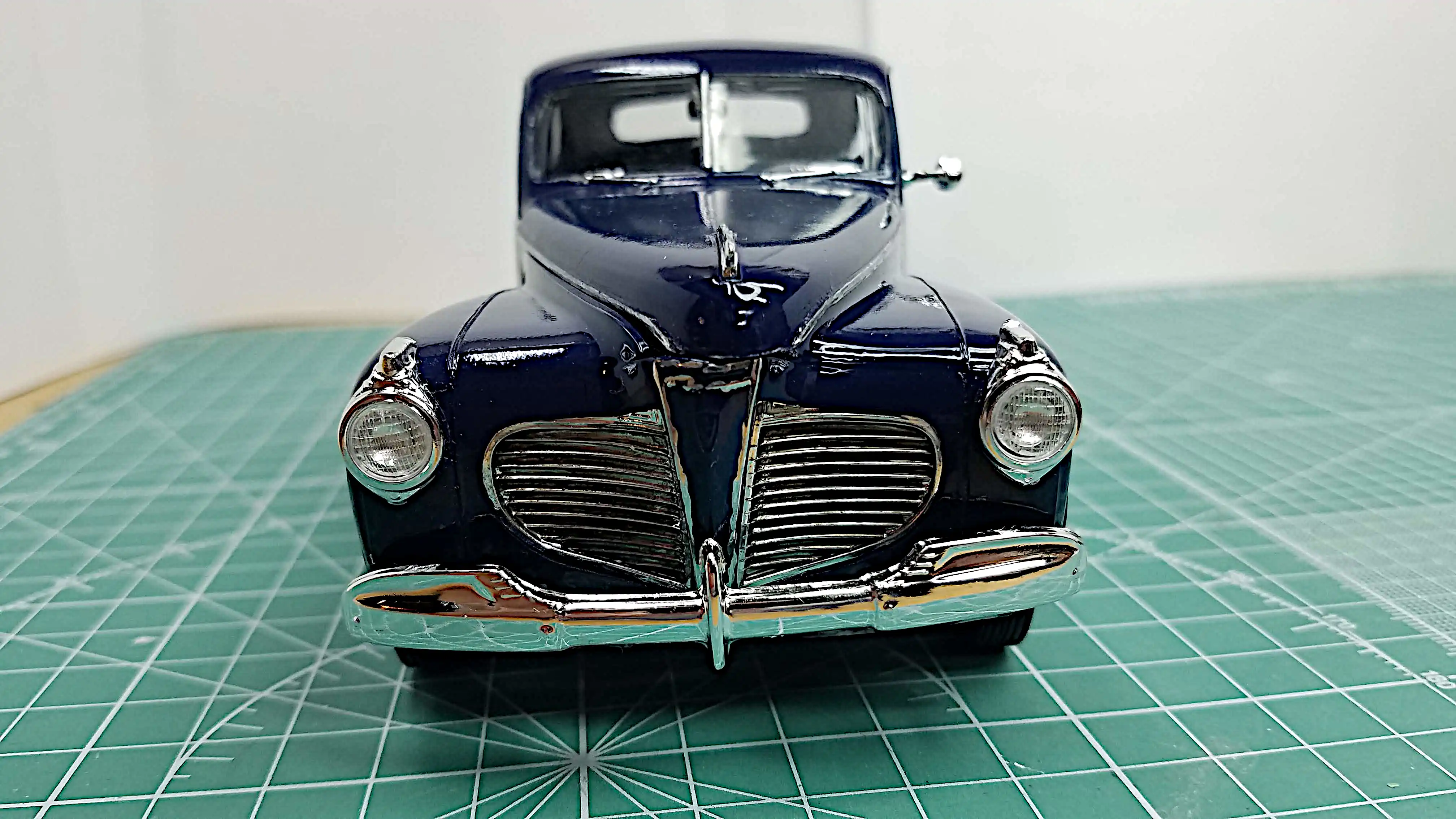 The 1941 Plymouth Coupe is finished - Front View
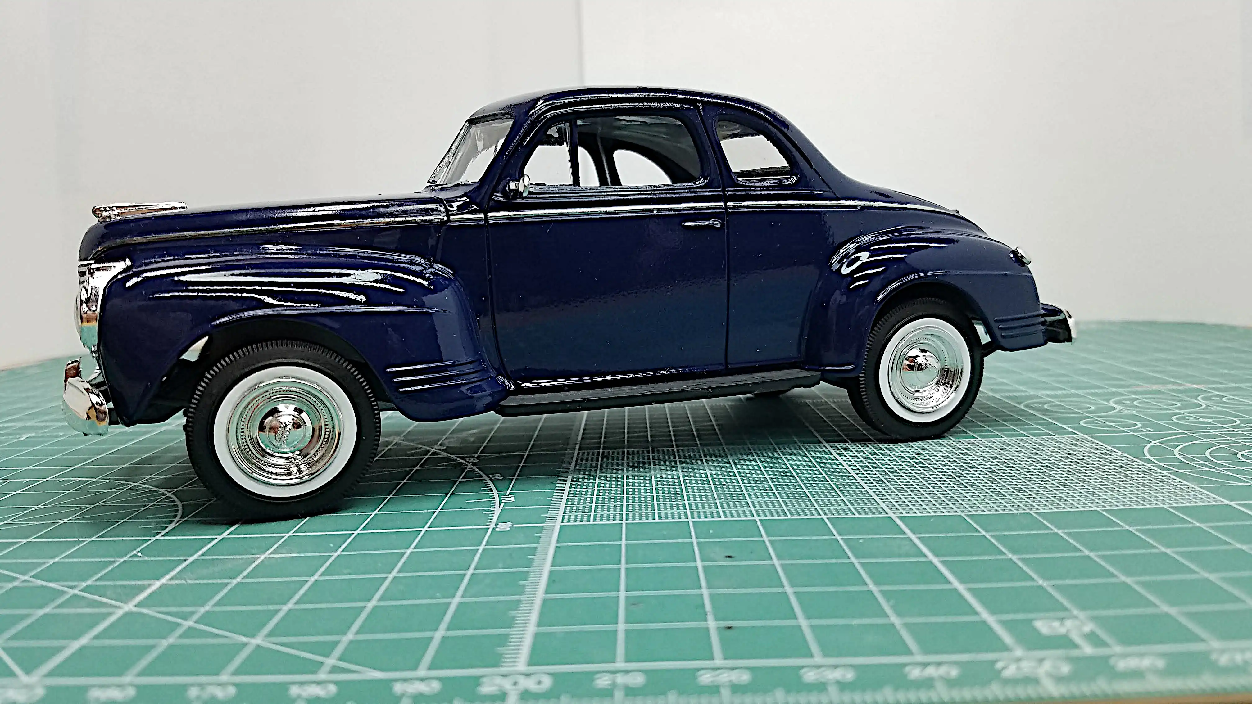
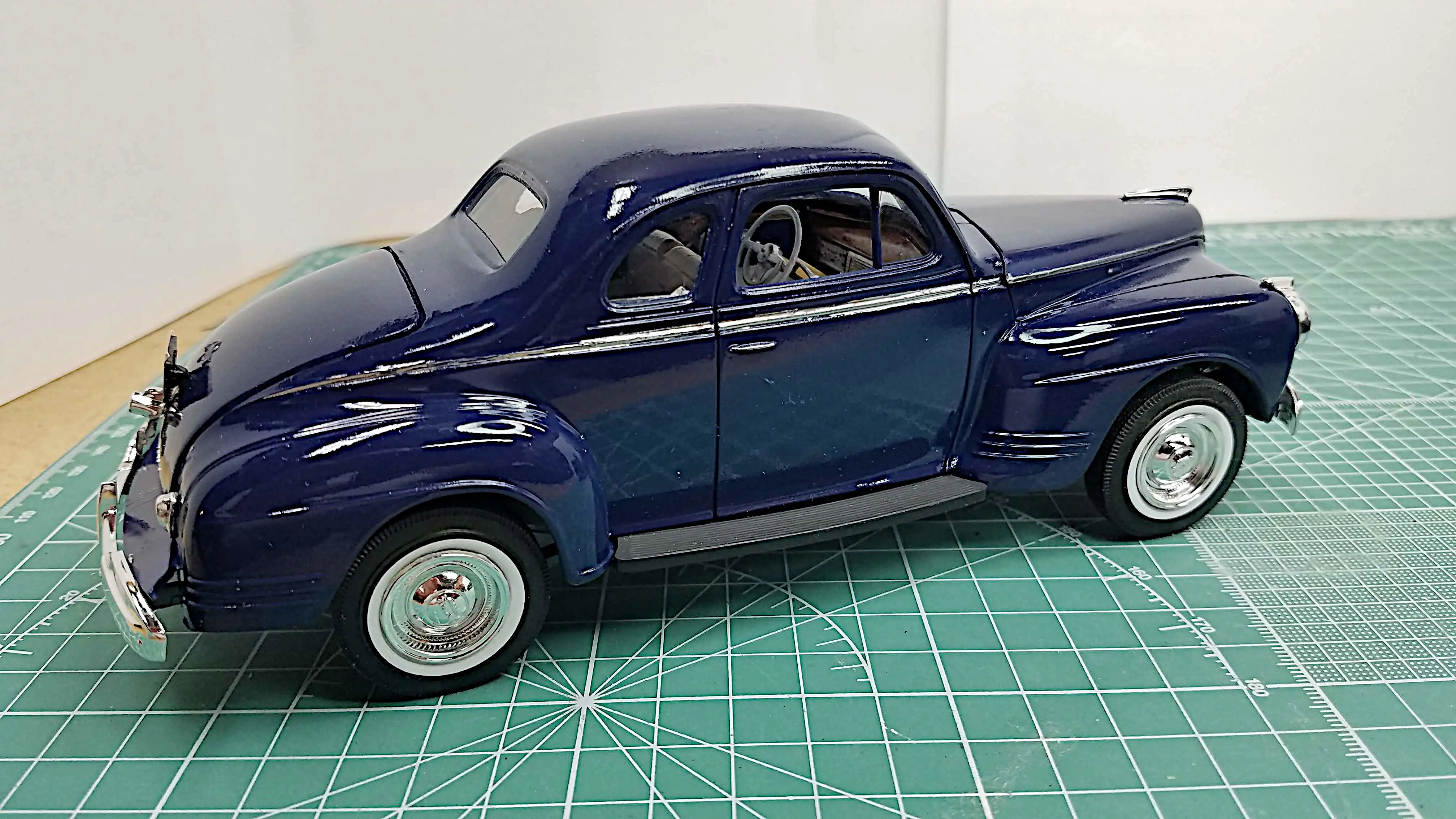
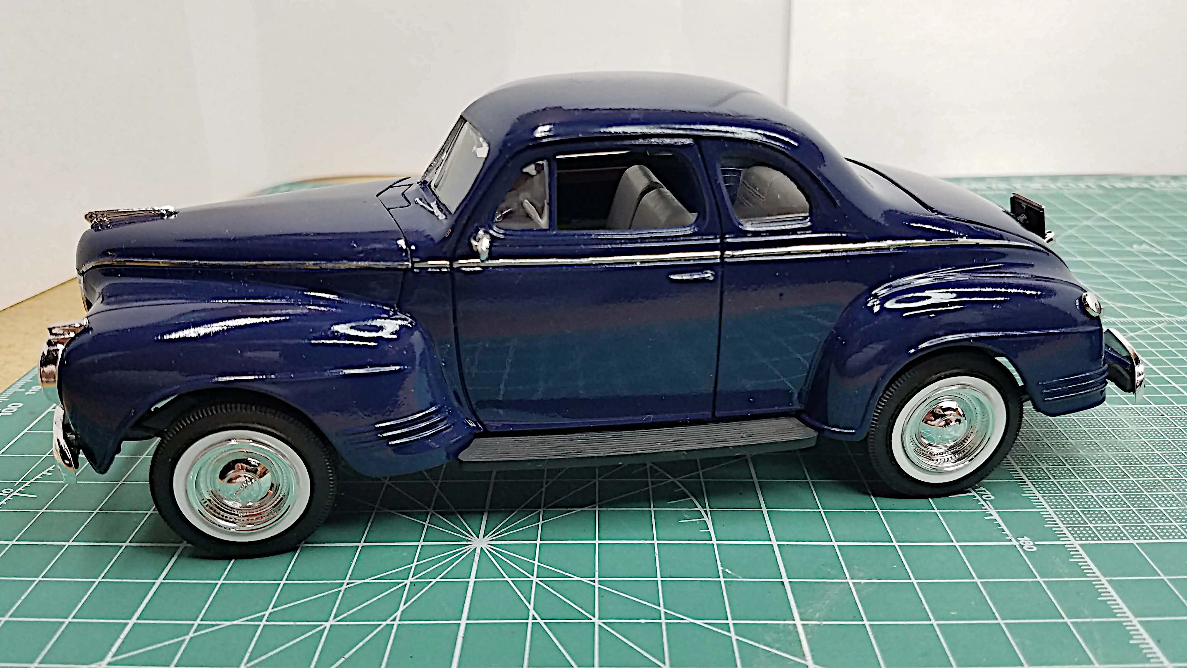 The 1941 Plymouth Coupe is finished - Left Side
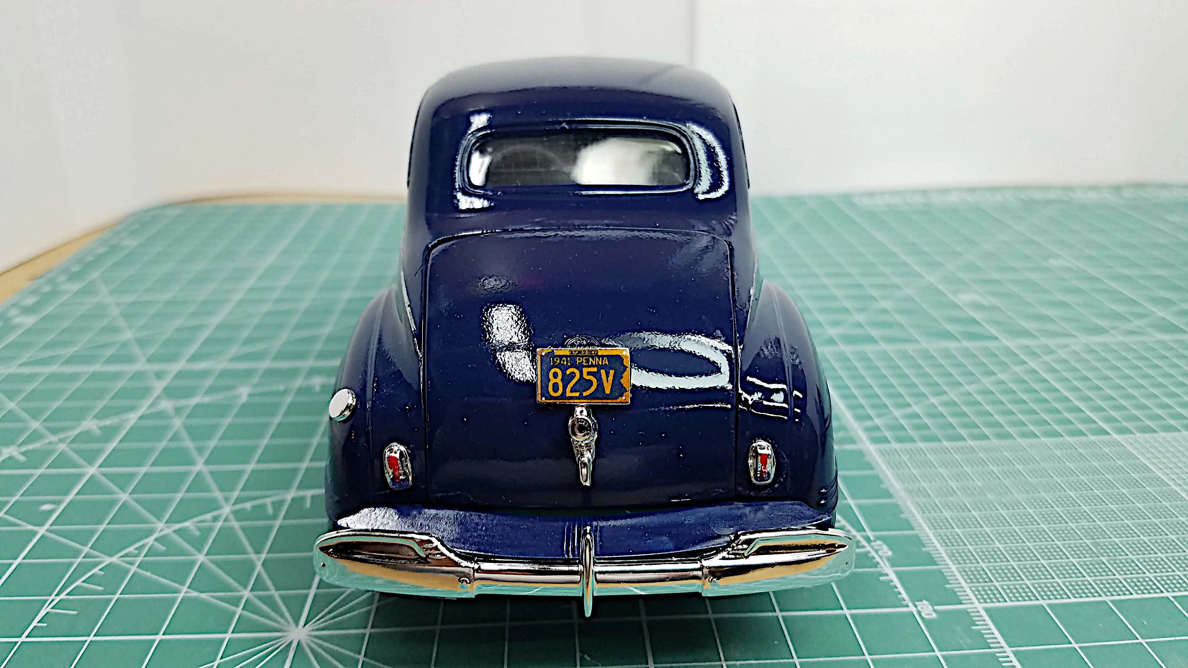 The 1941 Plymouth Coupe is finished - Rear View
 The 1941 Plymouth Coupe is finished - Right Rear Corner
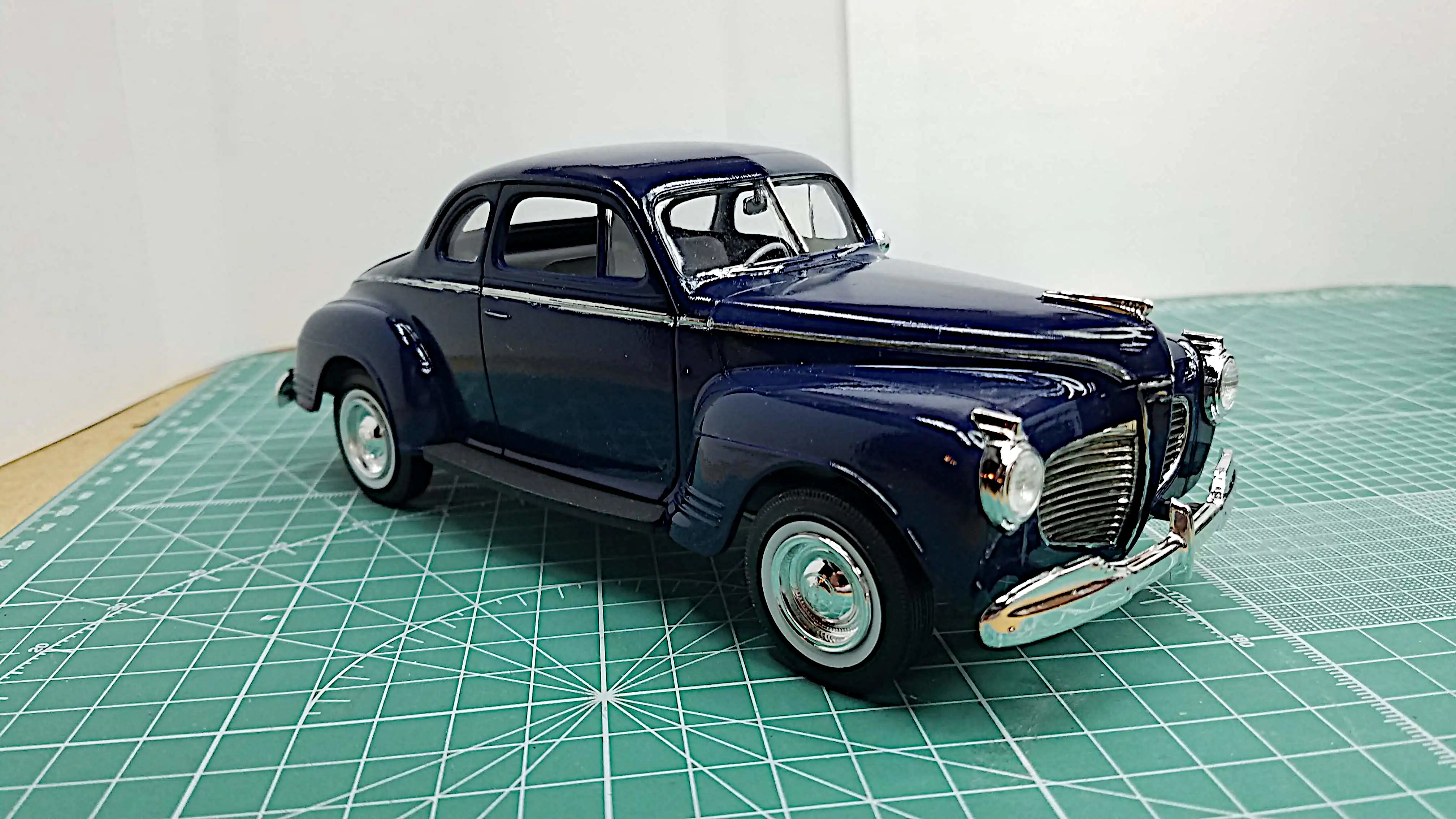 The 1941 Plymouth Coupe is finished - Front Right Corner
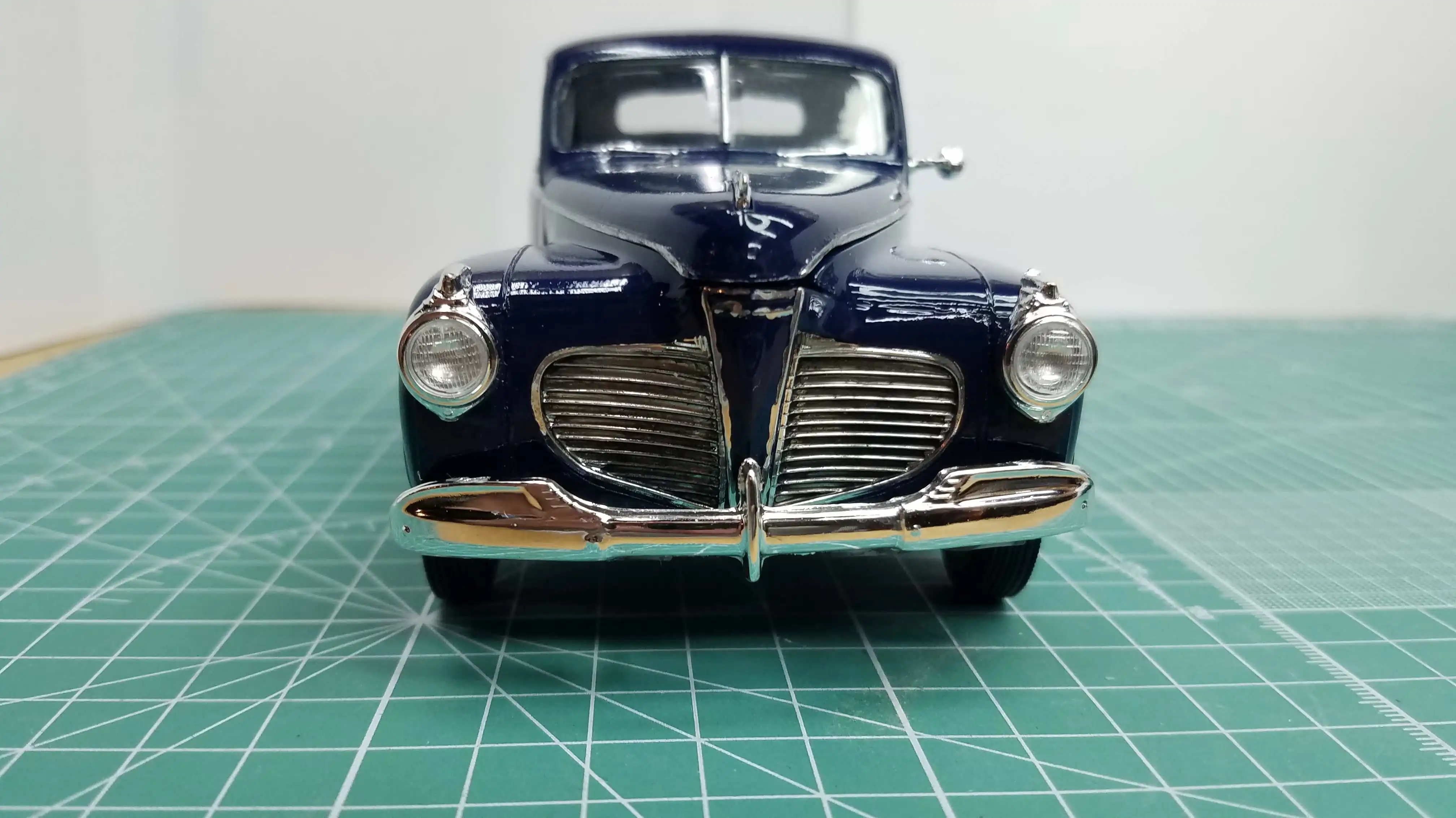 The 1941 Plymouth Coupe is finished - Front View
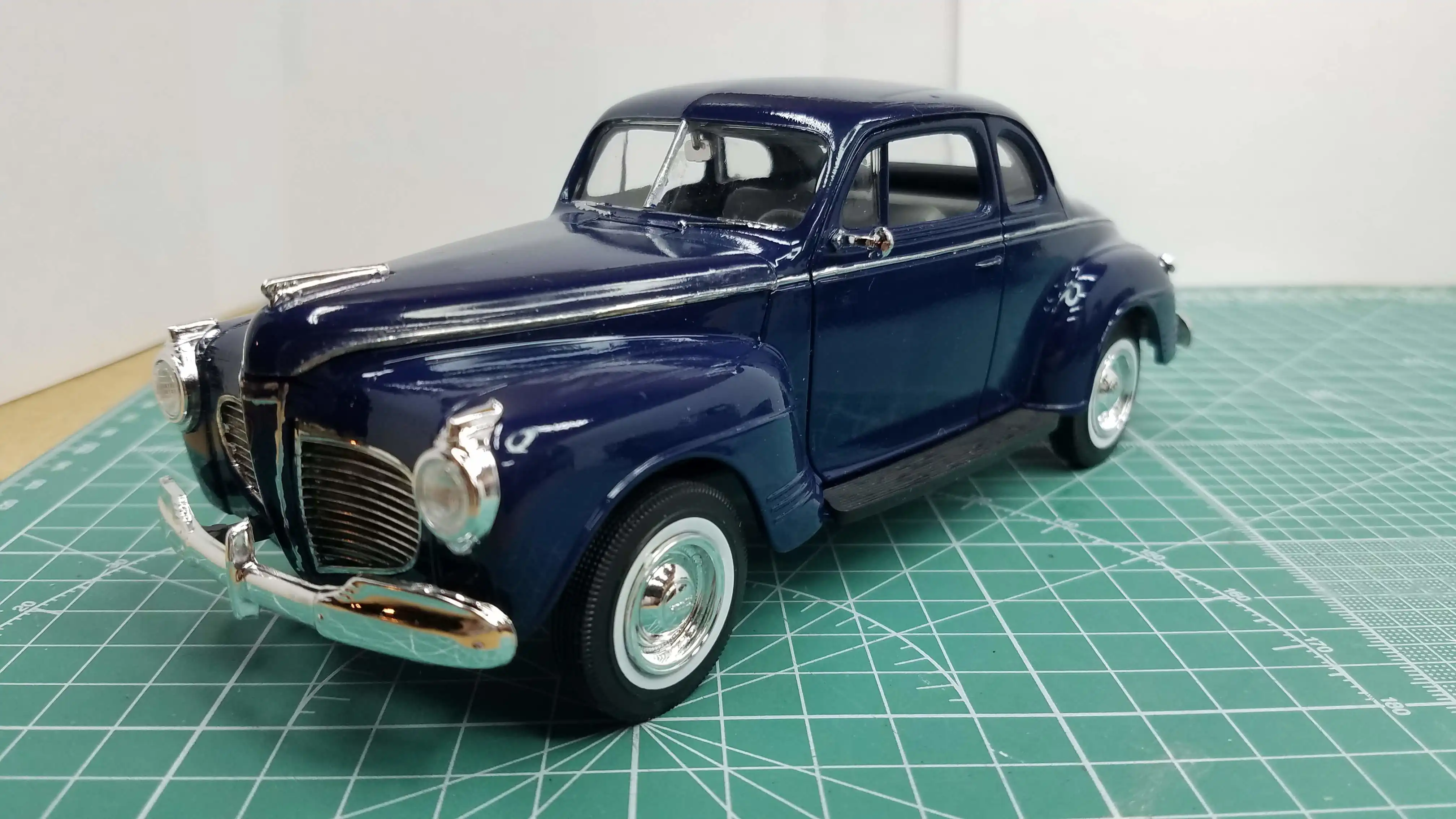 The 1941 Plymouth Coupe is finished - Front Right Corner
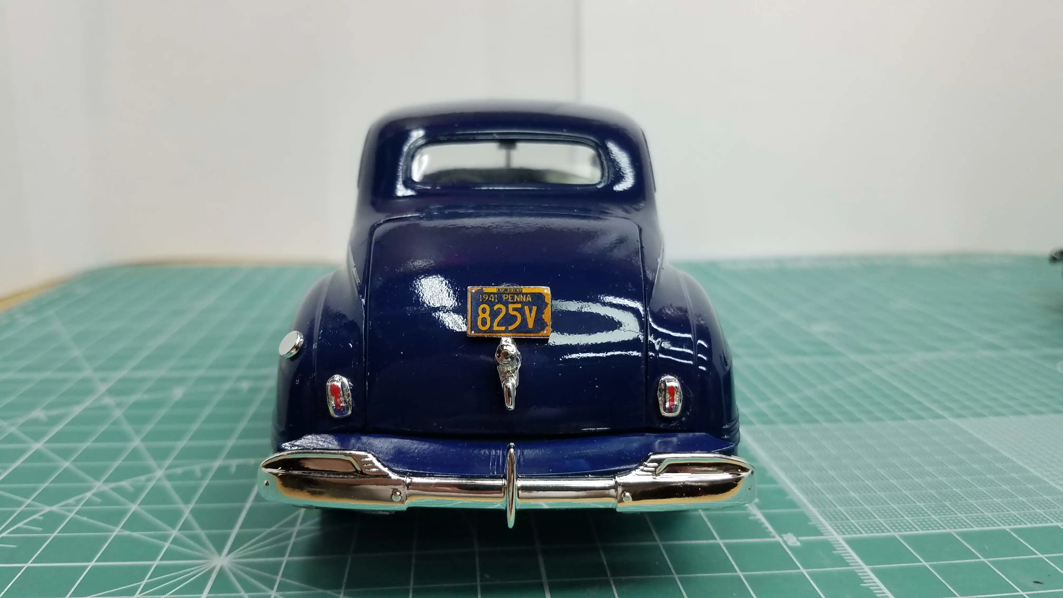 The 1941 Plymouth Coupe is finished - Rear View
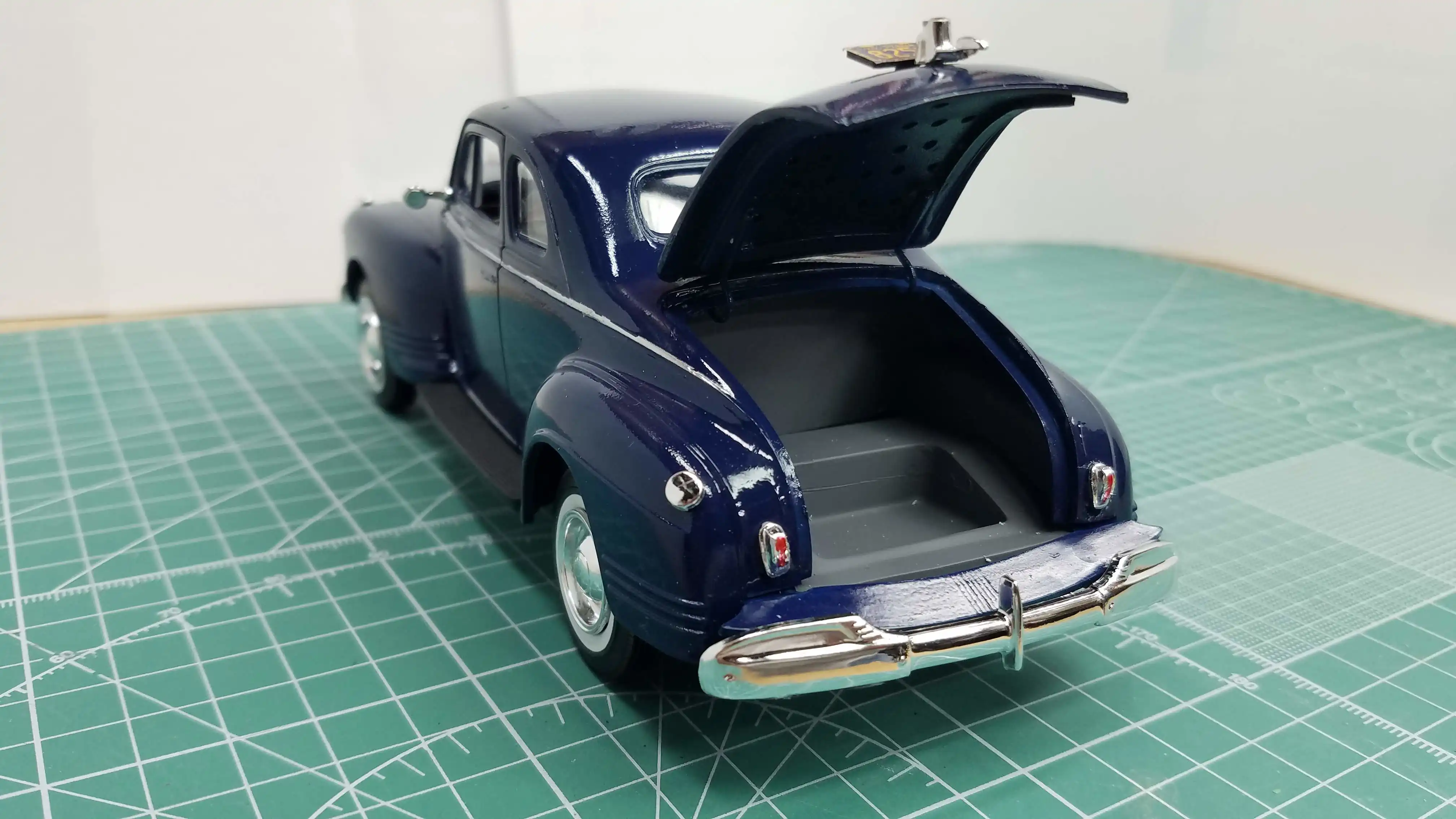 The 1941 Plymouth Coupe is finished - Right Rear Side with Trunk Open
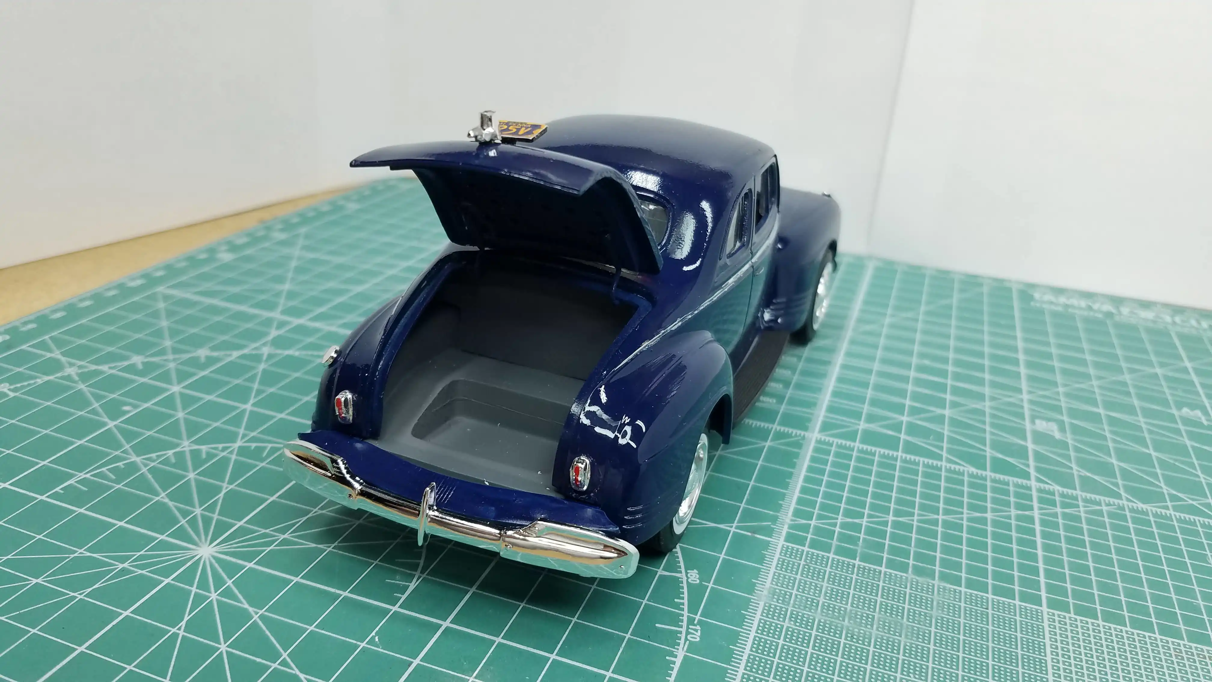 The 1941 Plymouth Coupe is finished - Left Rear Side with Trunk Open
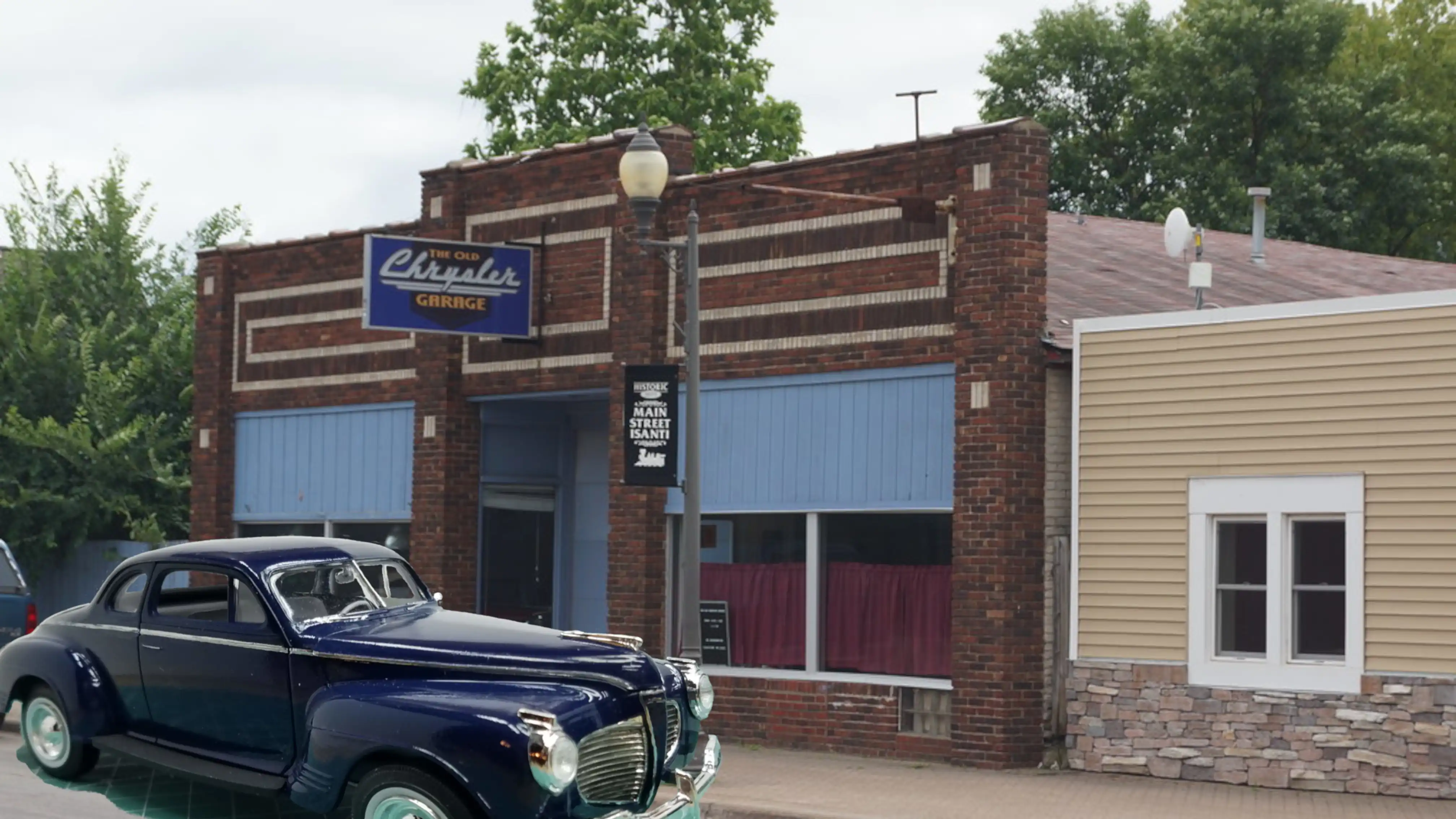 Finished 1941 Plymouth Coupe superimposed in a scene
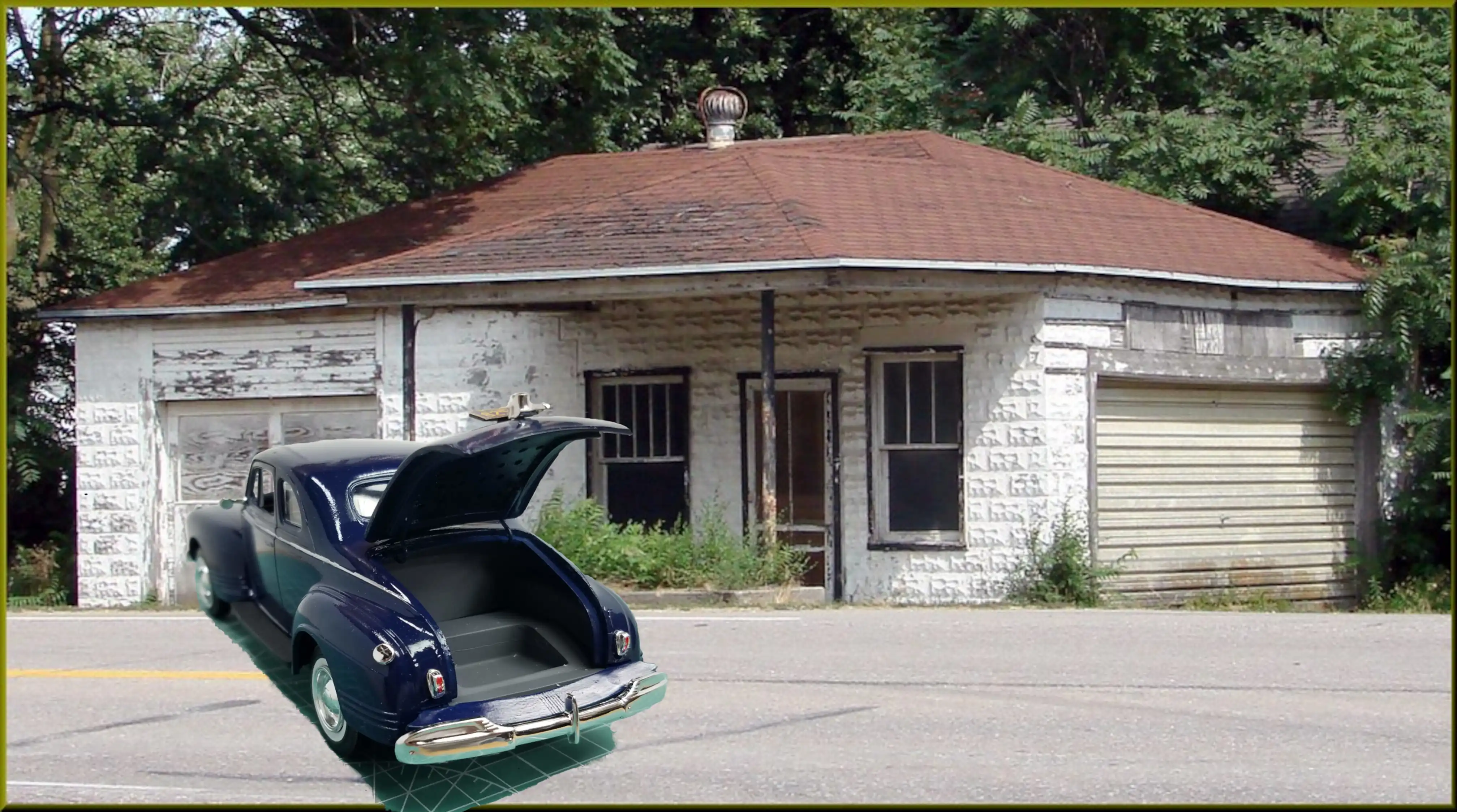 Finished 1941 Plymouth Coupe superimposed in a scene
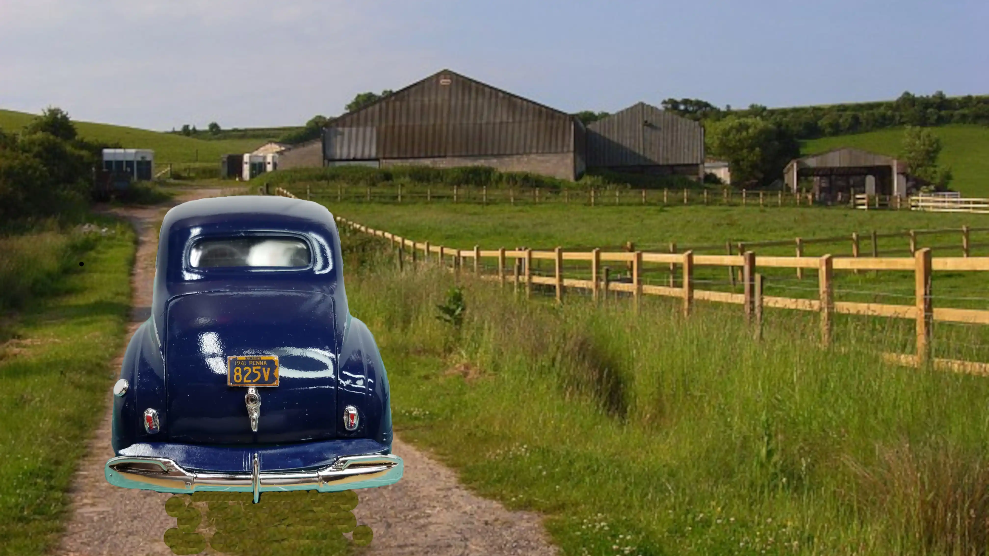 Finished 1941 Plymouth Coupe superimposed in a scene
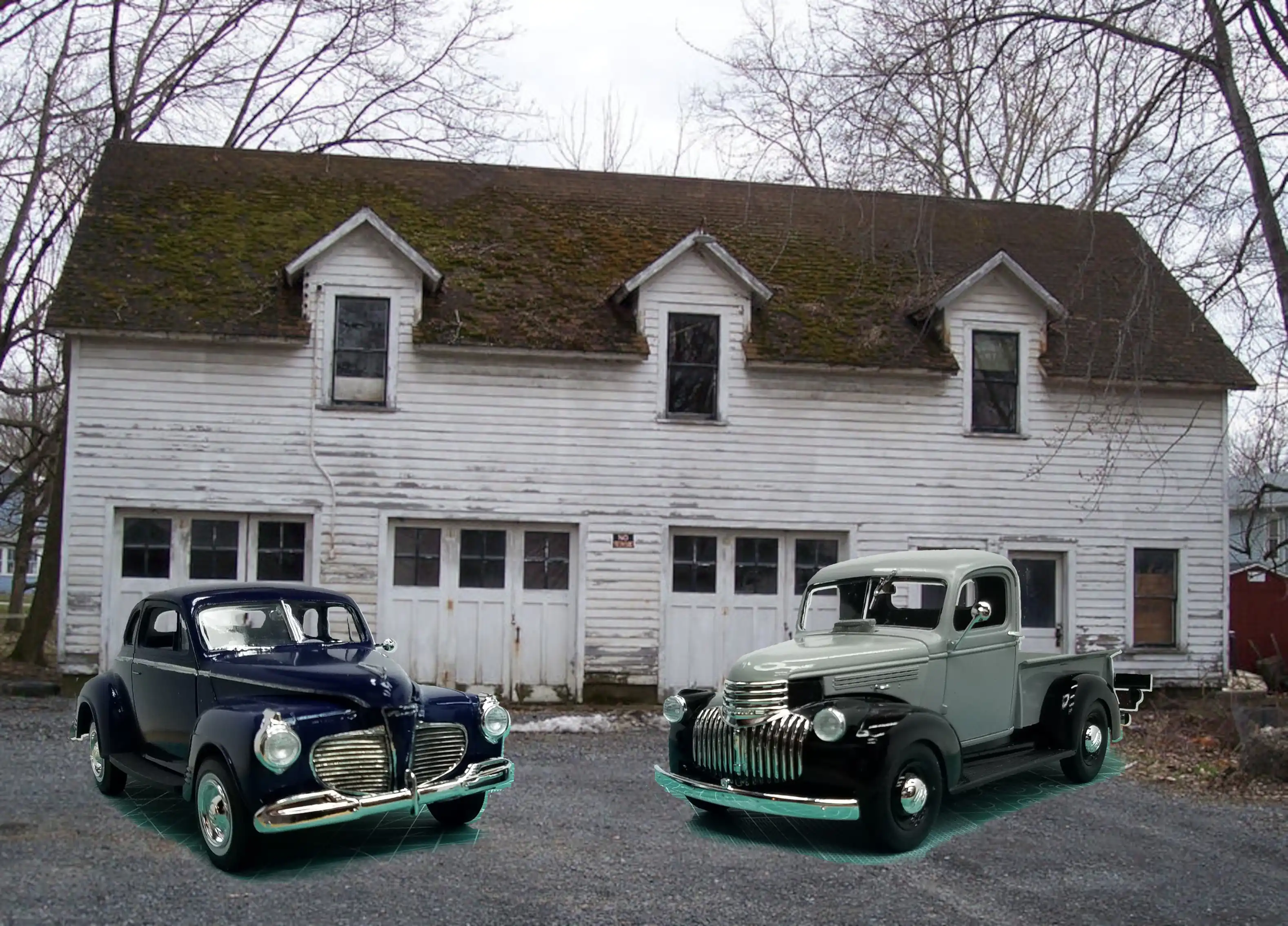 Finished 1941 Plymouth Coupe superimposed in a scene

