A Brief History of the Model 'A'
Taken from the side of the model box
The Ford Model "A" was among the most successful cars ever
producted. The Model A was the first ford to use the
standard set of driver controls with conventional clutch
and brake pedals; throttle and gearshift.
Previous Ford models used controls that had become out of
date and uncommon to drivers of other makes. The Model A's
fuel tank was located in the cowl, between the engine
compartment's fire wall and the dash panel. The fuel was
distributed to the carburetor by gravity. In cooler climates,
owners could purchase an aftermarket cast iron unit to place
over the engine's exhaust manifold to bring heated air into
the cab. A small door could be opened or closed to adjust
the amount of hot air entering the cab. Model A was the first
car to have safety glass in the windshield.
The Soviet company,
Gorkovsky avtomobilny zavod (GAZ), (Gorky Automotive Plant),
which started as a cooperation between
Ford and dthe Soviet Union, made a licensed version of the
Model A from 1932-36. The car later formed the basis for the
Ford-A Izhorsky (Armoured Car) (FAI)
and
Russian Broneavtomobil 20 (BA-20)
armored car, which saw significant use as scout vehicles in the
early stages of World War II.
Why the roof of the Model 'A' was not metal?
The roof of the Model 'A' was not vinyl. Vinyl did not exist at that time
period. The material used at that time was a long grain, leather-like material, often
referred to as Cobra Long Grain. There are several theories as to way
Ford used leather for the roof, here are some of those theories:
-
Compound curves needed to be made, and welding was not far enough
developed to make these curves.
-
Henry Ford was just trying to save money.
-
They were built during the depression, and steel was difficult to get.
-
Because of the rough roads of the time, frames were given the ability
to twist and flex. No flat piece of steel the size and position of
the roof would remain straight for very long.
-
The technology for stamping a large area of steel to form a roof was
not yet available and the roller mills in U.S. Steel mills could not
roll sheet wide enough to span the top.
These are just a few theories by different people as to way Ford did not
have steel roofs. Which one(s) do you think could be true, or not?
The above information came from the
Ford Barn
Video/Photo/Assembly Journal
Skip's Messy Workbench ⇔ All rights reserved ⇔ Copyright © 2023-2025
Skip's Messy Workbench
⇔ Last updated: November 25, 2025

 1931 Model 'A' 2-Door Sedan Minicraft Box Art
 The Decal Sheet
 Engine parts for instruction sheet steps 1 & 2
 Left side of the engine block, head, oil pan and water pump
 Right side of the engine block, head, oil pan and water pump
 A hole needs to be drilled to fit a bracket
 Broken dip stick and bracket
 Assembling the frame
 Assembling the frame
 Engine parts ready for primer
 Wheels had to have the primer stripped off
 Left fender will need work
 Injector pin marks filled
 Experimenting with colors for the body
 Exhaust manifold painted
 Right front fender mounted
 Fan belt pulleys drilled open
 Properly install the oil filler pipe
 Wheels are/were painted and repainted
 Drilled a mounting hole in the engine block
 Bracket installed on engine
 Carburetor is mounted
 Checking cooling fan to radiator fit
 Had to re-glue the wheels
 Front wheels inner hub (brake drum)
 Wheel parts
 Front suspension and steering rod installed on one wheel
 Front wheel assembly complete
 Engine mounted in the frame
 Starting to work on front and rear suspension
 The front suspension is mounted
 Rear axle, drive shaft, leaf spring and stabilizing arms is built
 Front and rear suspension is installed
 Front and rear suspension is installed
 Front and rear suspension is installed
 Left side view of completed chassis
 Top view of completed chassis
 Bottom view of the completed chassis
 Test spoons for body colors
 Test spoons showing body colors with interior colors
 Fenders are painted
 Body parts are masked for the application of the light blue color
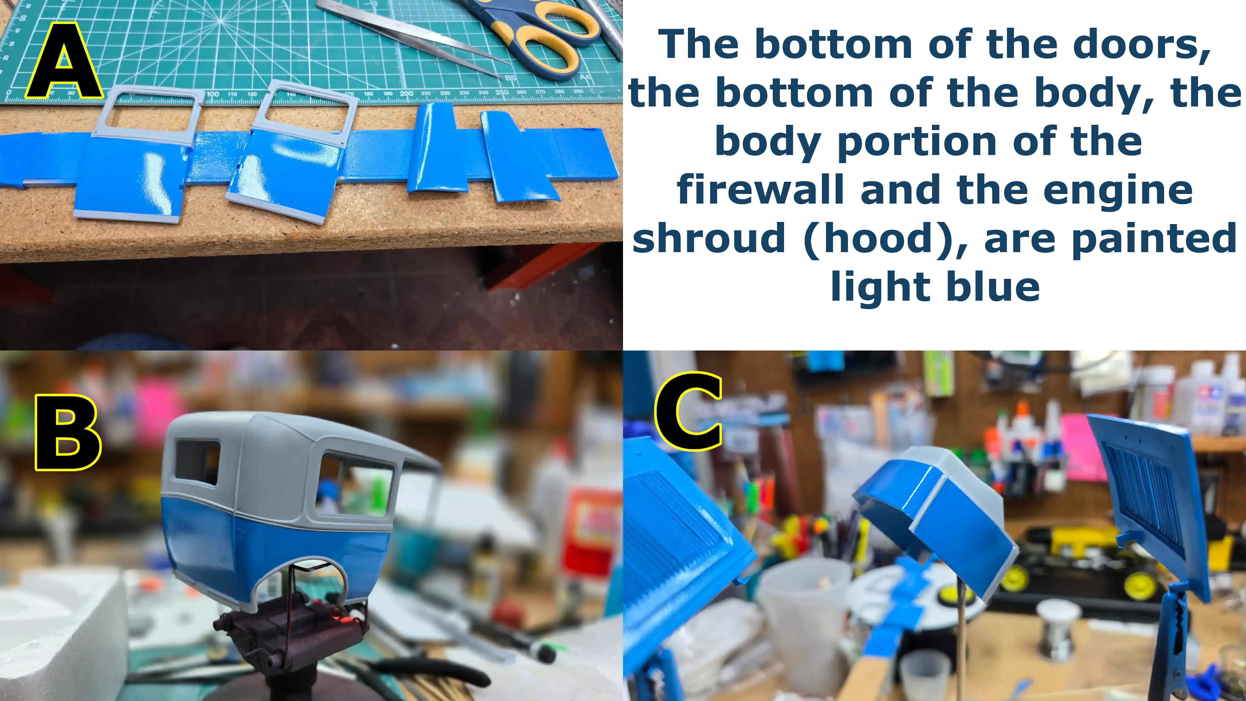 Light blue portions of the body are painted
 Radiator dress frame is chromed
 Body parts masked to apply the dark blue
 Dark blue portions of the body are painted
 Masking the body for the third color(s)
 The body parts are painted
 Interior door panel painted and detailed
 The front seats are finished
 Interior floor cut open for battery
 Another view of the body parts painted
 Another view of the body parts painted
 Battery mounted with cable clamps installed
 Negative battery wire attached
 Battery is wired
 Interior floor and seats installed
 Installing rear interior side panels
 Fenders and interior floor are mounted on the frame
 Fenders and interior floor are mounted on the frame - Front view
 Spark plugs wired with copper strips
 The glass does not fit
 Engine shroud left and right side
 Left and right engine shroud showing hinge working
 Engine shroud side hinges work
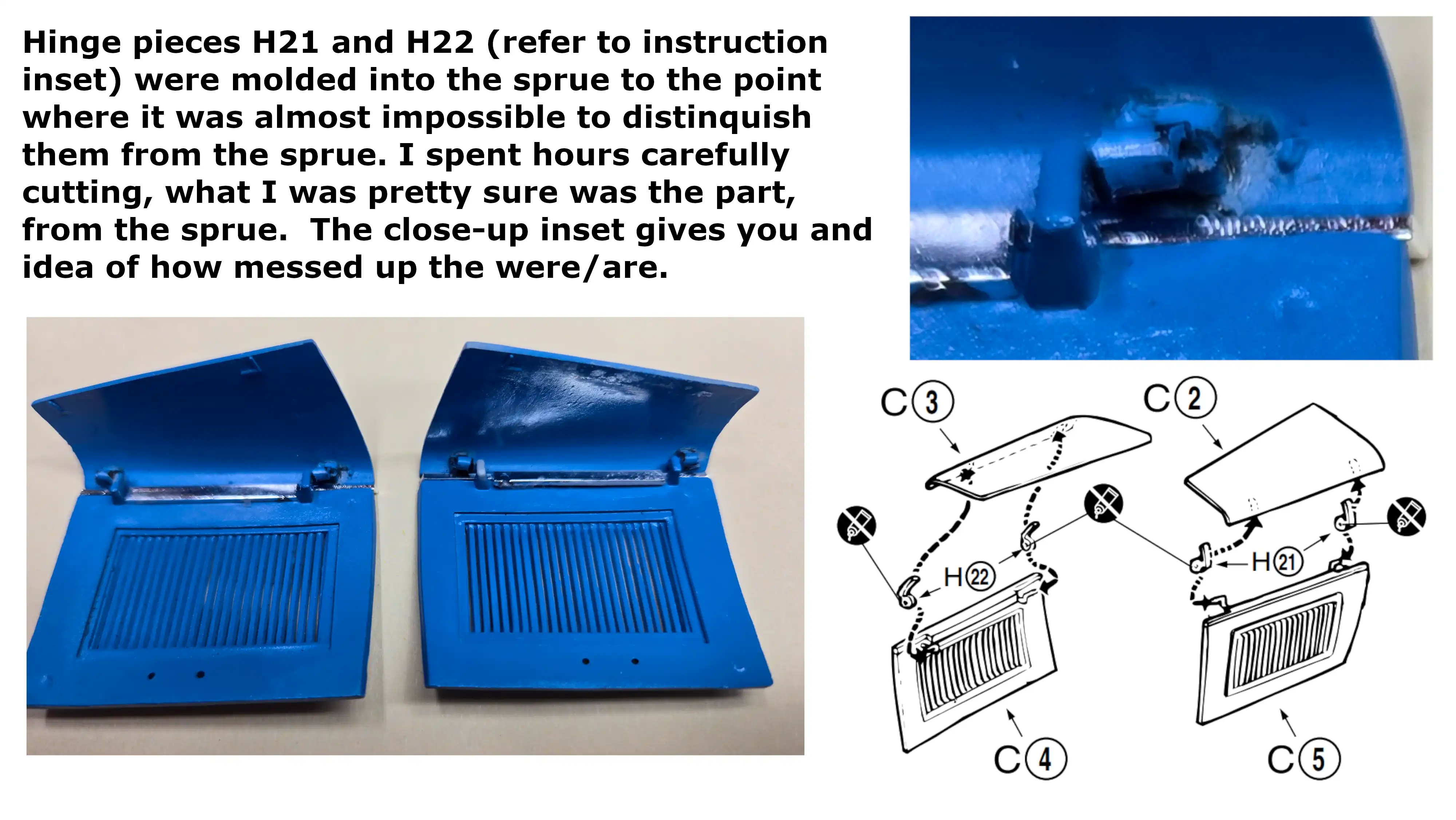
 Engine shroud top hinge pieces are in terrible shape
 Started assembling the door hinges
 Huge top gap between the left and right engine shroud sides
 Dimension between rear fenders
 Dimension between rear interior side panels
 Body setting cock-eyed on the frame

