This page contains a photo journal of my build for the 1968 Dodge
Dart Hemi 2-n-1. The '68 Dodge Dart Hemi is the kit being built
for the Unified Scale Auto Content Creator (USACC) build that
runs from: September 15, 2024 to March 16, 2025.
In each of the photo boxes is a button labeled 'Display Photo Text'.
Click the 'Display Photo Text' button to display the descriptive text
for the photo. There can also be other links within the text.
At the end of the text is a button to 'Close Text'.
Clicking or tapping on any photo will open an enlarged version of that
photo in a new tab or window depending upon how your browser is configured.
My plan for this kit is to build a car that would have been a
late model stock car that could have run on the 1/2 mile dirt
track oval during the 1970's and early 1980's in
Nazareth Speedway, Nazareth, PA
The 1/2 mile dirt track is no longer in existence; what a
loss!
This photo shows the Box Art for the 1968 Dodge Dart
Hemi 2-n-1 being used for the 2024/2025 USACC build.
Information on this kit can be found on
Scalemates.
As I stated in the lead-in to this project, my plan is to
build my version of a vintage late model stock car that would
have been seen on a dirt track in the late 1970's. Some of my
buddies at the time had cars that they ran at the 1/2 mile
dirt track in Nazareth, PA, in Middletown, NY at the Orange
County Fair Grounds, at Flemington, NJ and in Reading
(pronounced 'Redding'), PA; Jack Zeiner and his brother Tom,
both late model champions at Nazareth and the Metzger brothers,
Gary and Sterling (pugsly), although never won a championship,
were competitive and a track favorite.
Only one of these cars is a Dodge Dart and that is picture '4'.
Pictures 1, 2 and 3 are random photos found on the web. Photos
5 through 8 are from the
Nazareth Speedway Facebook Page.
The 1/2 mile dirt track is no longer in existence; what a
loss!
The following numbered list corresponds to the numbered tiles
in the photo below. Photos 5 through 8 are cars and drivers
from Nazareth, PA:
The numbers on each tile of the following photo refer to the
above numbered list. Click a number in the above numbered
list to open a larger image of any of the associated tiles
in the tiled photo below.
Decal sheet from the kit. If you want and/or need a copy of
this sheet, simply:
On a PC, right-click on the image and select Save Image
As... from the context specific menu (pop-up). Then
select a location to save the file.
On a Mac, Control-click and select the option to save the
image.
On a cellphone long tap and select Download from the menu.
Open the image in a photo editor and to keep the proper scale,
the image should be: 8.147 inch x 5.147 inch (206.934mm x 130.734mm),
with a resolution of 300px x 300px. The size of the image in
pixels should be: 2,444px x 1,544px.
I always like trying something new with the
USACC build. I've never used a 3D printed
engine and although I like the hemi that
comes with the kit, I thought I'd like to put
some kind of high performance Mopar Slant 6
under the hood.
I had a 225 Slant 6 in my 1966 Plymouth
Valiant 200 and I loved it. You couldn't
kill it.
I found a Slant 6 HyperPak at VCG Resins and
bought it thinking this is the engine I'd be
using. Then, a few days later, while looking
for racing seats I saw the slant 6 Hemi Turbo,
also at VCG Resins. I immediately placed an
order knowing this would be the engine of
choice for this build.
These images are from the VCG Resin website.
The HyperPak is on the left and the hemi turbo
is shown in two views on the right.
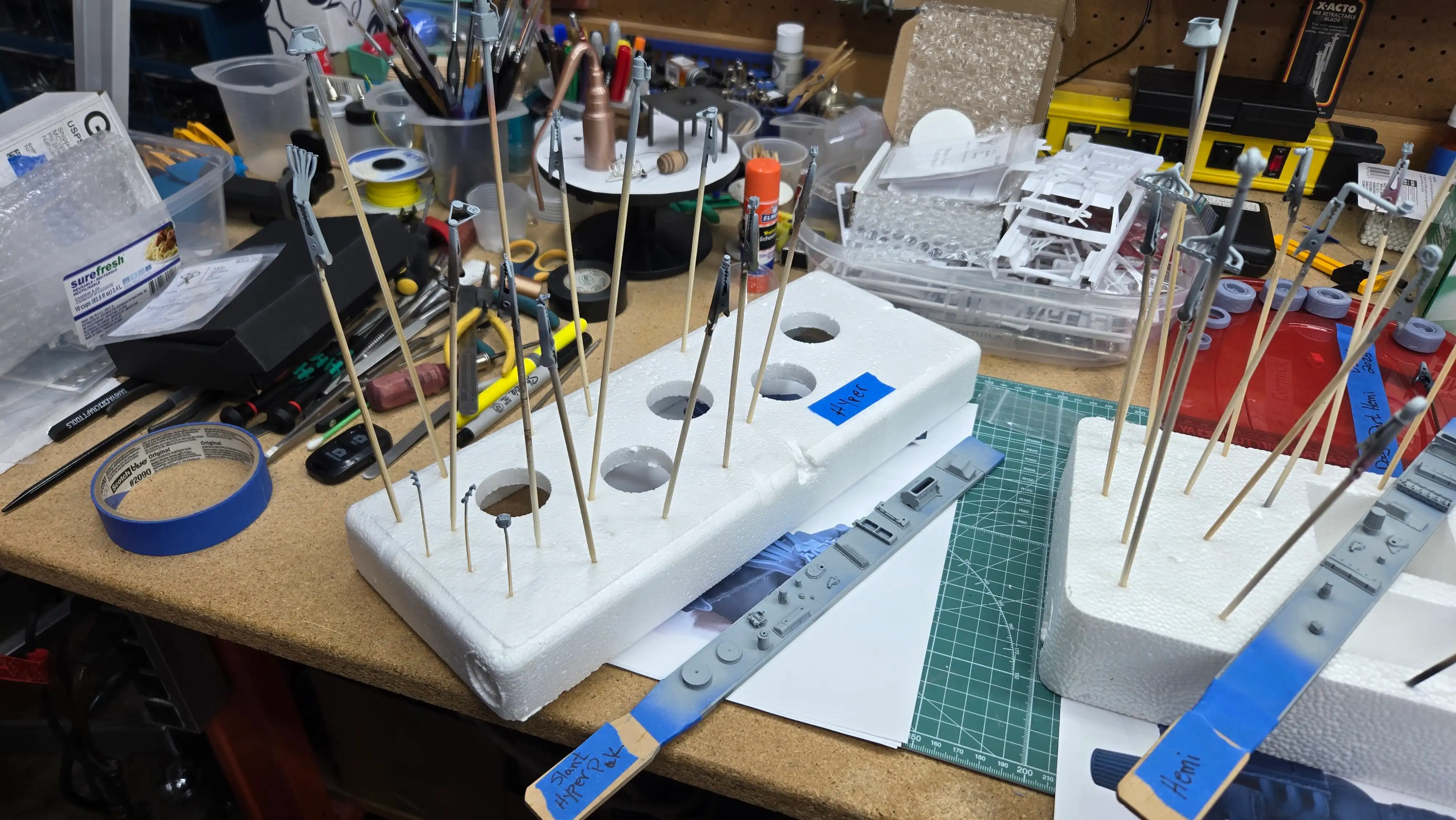
These are the parts that come with the VCG
Resin Slant 6 HyperPak engine. Since I'm
not going to use this engine in this build,
and I've never built a 3D printed engine
before, I thought I would start by building
this version. Some of the parts are very
small and I already lost the oil filler cap
to the Bermuda Triangle under my bench. It
will be easy to make one.
These are the parts that come with the VCG
Resin Slant 6 Hemi Turbo engine. This is
the engine I'm planning to use in the build.
I didn't know there was such a thing as a
Hemi Turbo Slant 6, so I did some research.
The performance specifications of this
engine are fabulous and I think it would/will
give most 8-cylinder engines a run for their
money.
This photo was 'super enhanced' to show
the body detail.
I'll be removing some of the body detail. This
photo shows some of the body detail I'll be
removing such as the front and rear side marker
lights, the emblems and the door locks. I'll
also be filling the location for the door
handle.
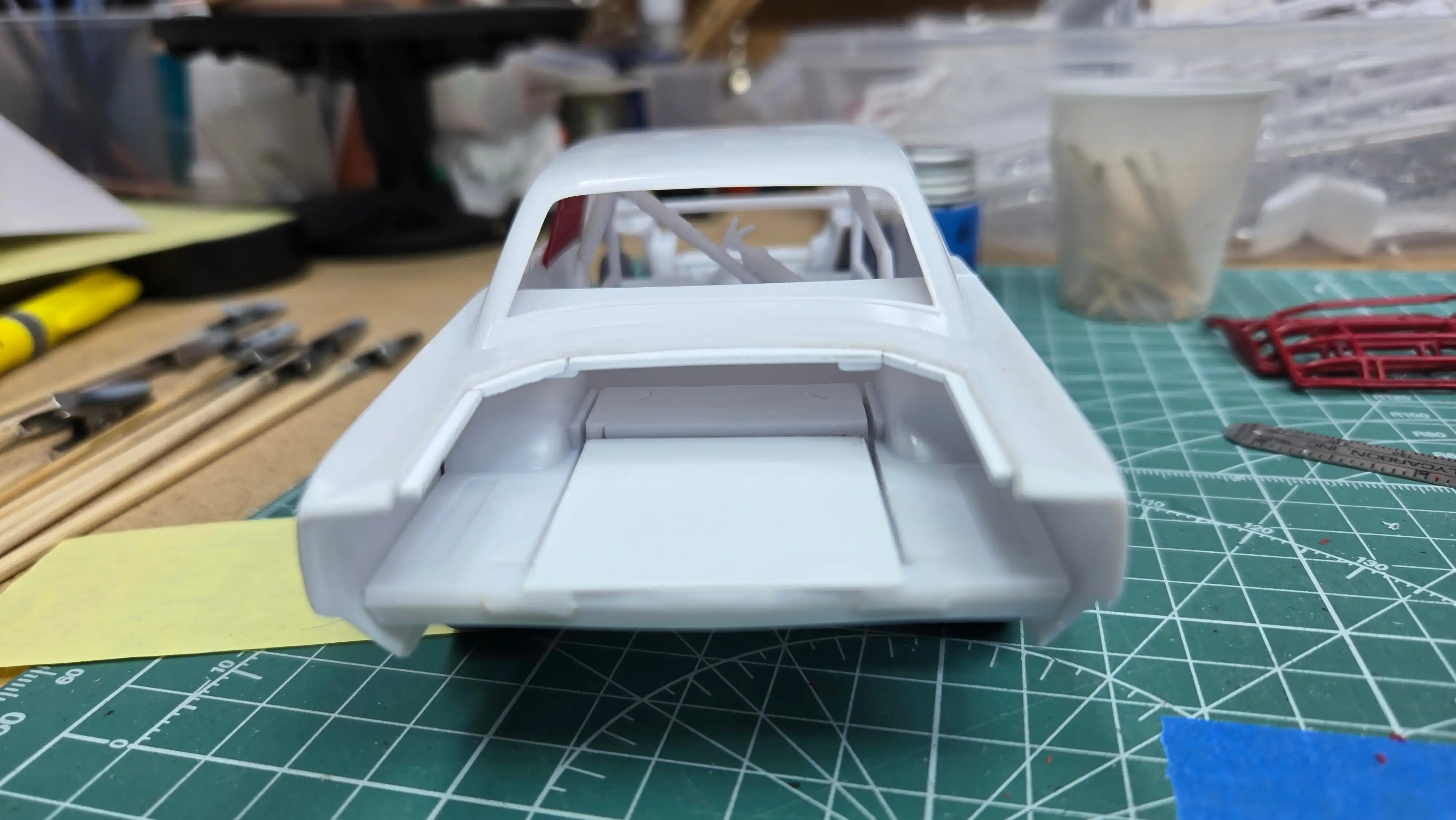
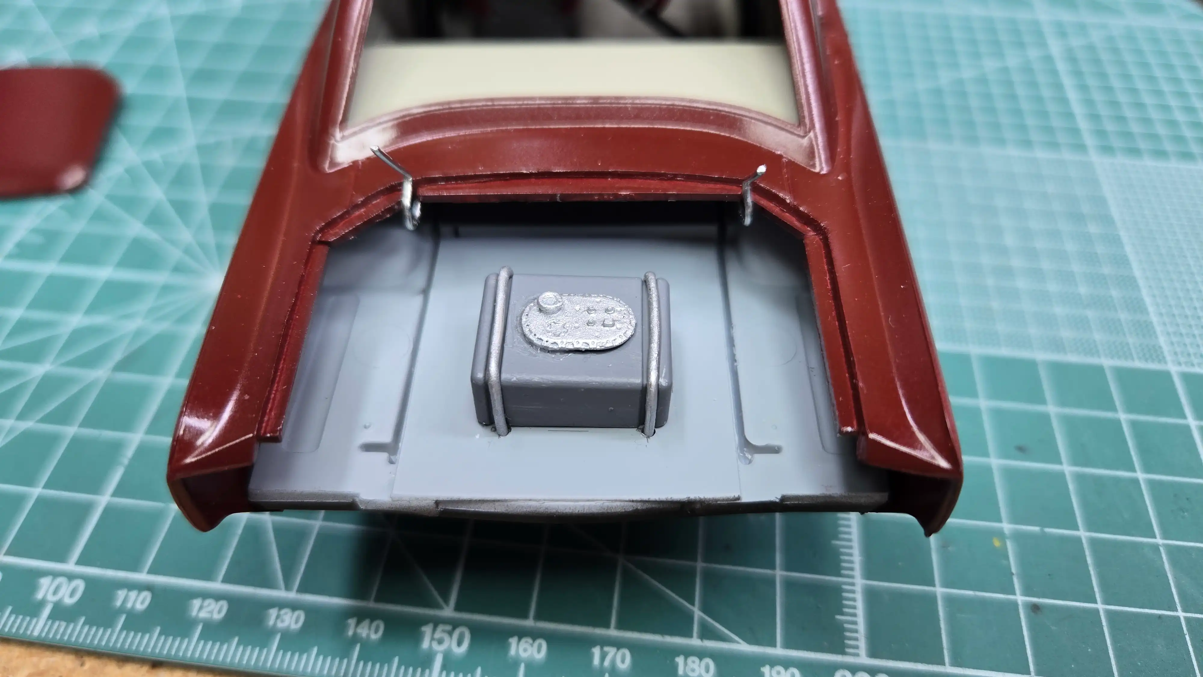
The trunk lid has been cut open and
hinges will be added. I'm opening the
trunk so the fuel cell can be seen, but
also, in street stocks, some teams
did not pipe the fuel cell to the outside
of the body and would lift the trunk
lid and put the fuel directly into the
cell.
After cutting off the sides of the roll cage,
to get the roll cage side to fit in the Dodge
body, the bottom strip of the roll cage must
also be cut off.
One side of the roll cage has been cut to
what I "think" will fit in the '68 Dodge
Dart body? I dry fitted the parts and they
seem to be fine; however, we all know that
sometimes things don't work out the way we
want them.
Both sides of the roll cage are cut to the
proposed size to have them fit in the '68
Dodge Dart body. I will be doing a final test
fit using some white glue to hold everything
together.
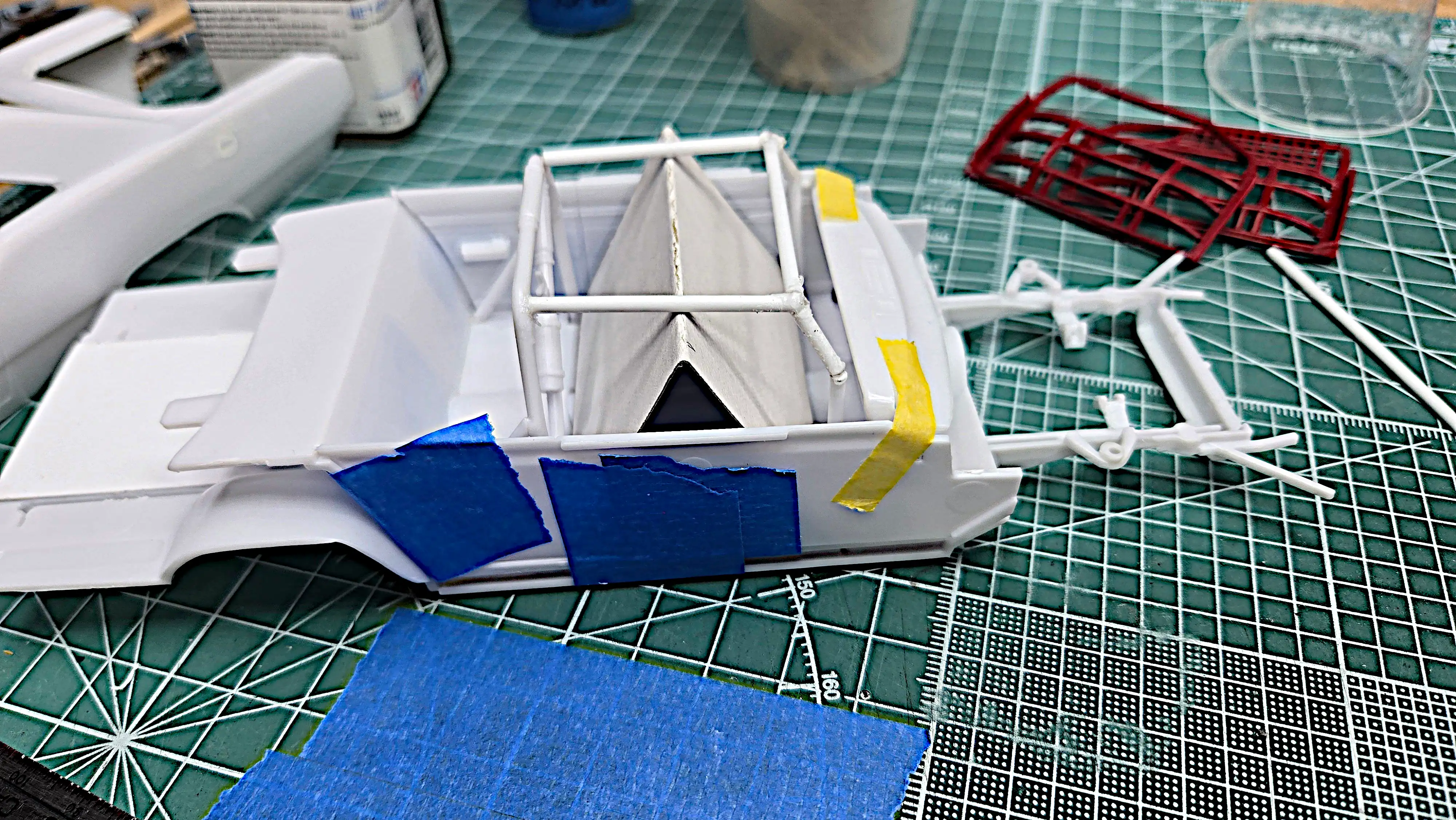
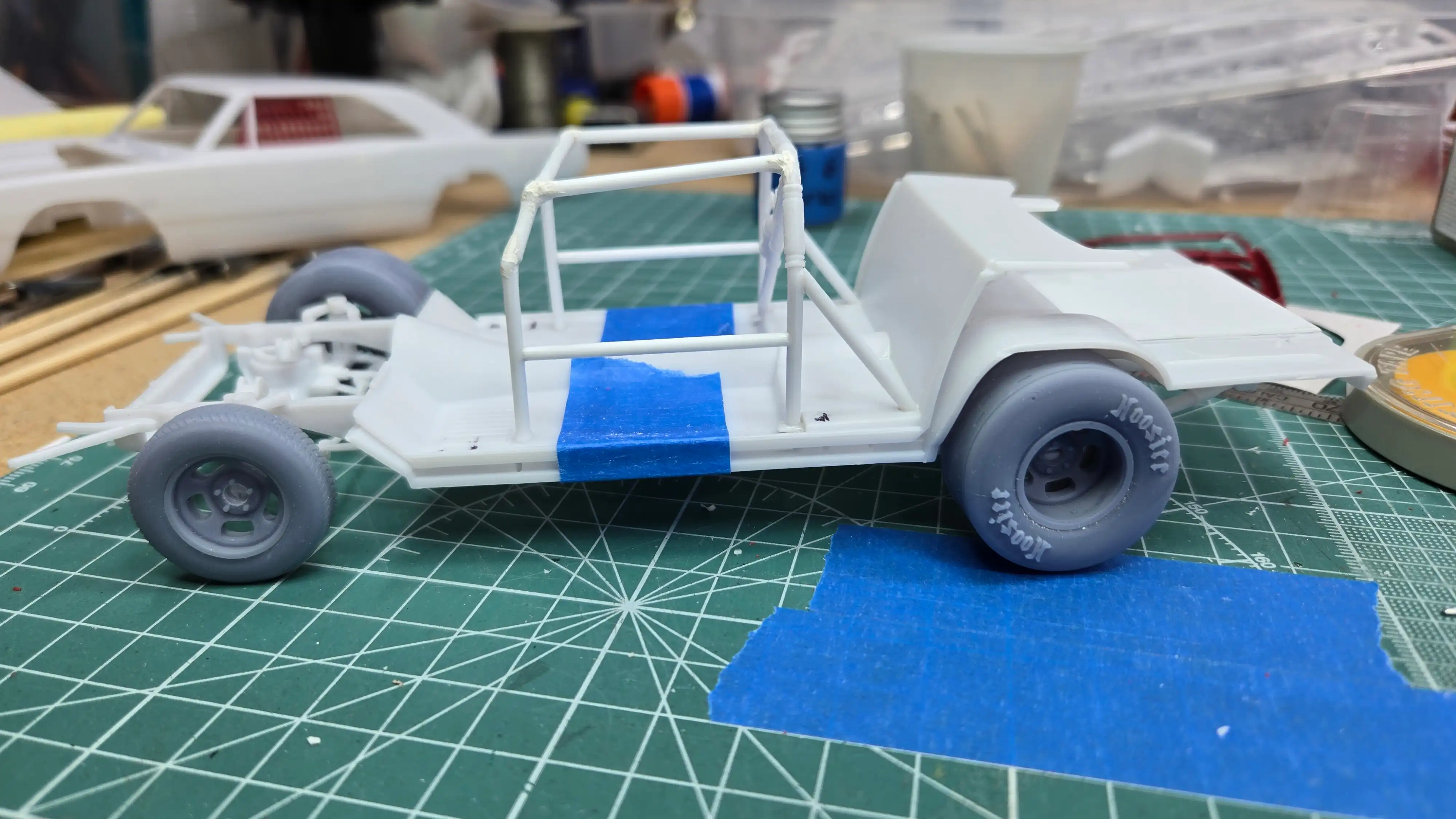
This is a back view of my scratch built roll cage.
I made a small helper to keep the top rails at the
same height. All I did was took a piece of thin
cardboard, measured the height from the floor to
the bottom of the top roll cage bar and then made a
fold, making a 'V-shaped' cardboard 'work horse'.
This kept the upper parts of the roll cage the
same height and also held them in place until the
glue setup.
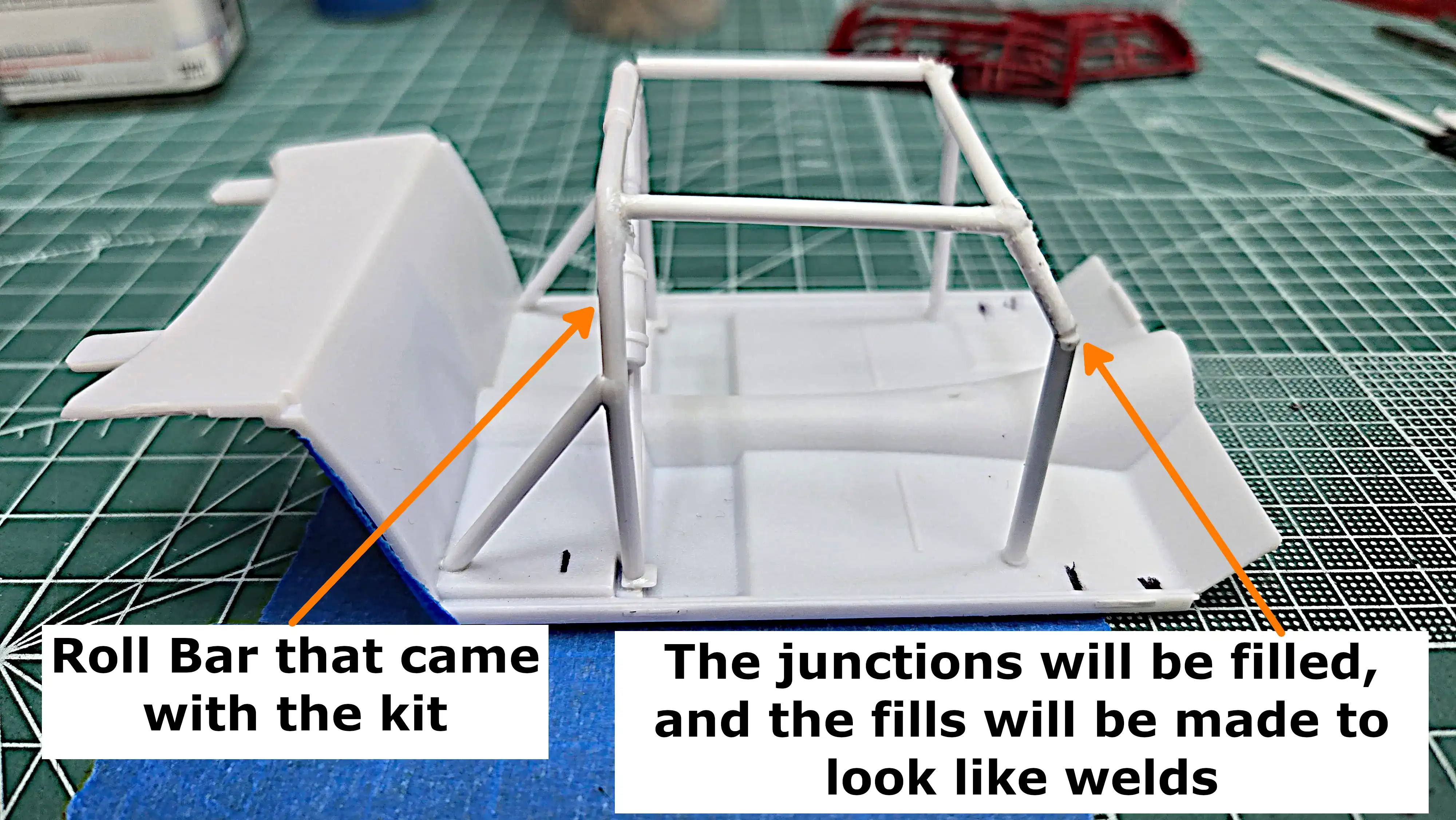
I scratch built a roll cage. I had tried to
use the premade roll cage from the Tim Richmond
Folgers Chevy Monte Carlo NASCAR; however, it
just didn't fit. And, it was an overkill for
the late model dirt track series. I used the
roll bar that came with the kit and built on
to it using Evergreen 212 0.080"/2.0mm rod.
This photo is of the right side as it was
built on the frame and floor pan. The joints
will be filled and made to look like welds.
The next couple of pictures are of the roll
cage from different angles.
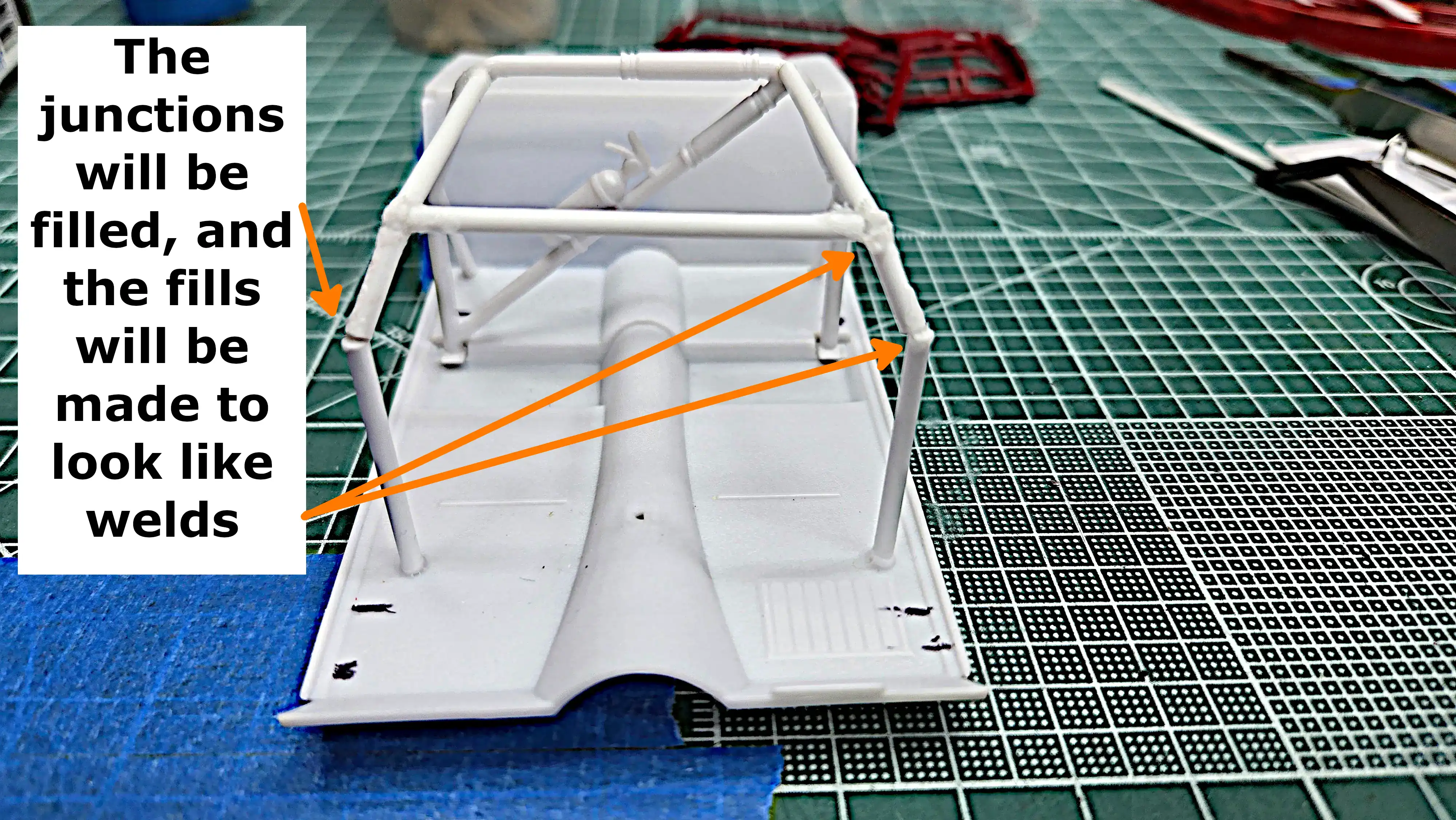
I scratch built a roll cage. I had tried to
use the premade roll cage from the Tim Richmond
Folgers Chevy Monte Carlo NASCAR; however, it
just didn't fit. And, it was an overkill for
the late model dirt track series. I used the
roll bar that came with the kit and built on
to it using Evergreen 212 0.080"/2.0mm rod.
This photo is looking at the front as it was
built on the frame and floor pan. The joints
will be filled and made to look like welds.
The next couple of pictures are of the roll
cage from different angles.
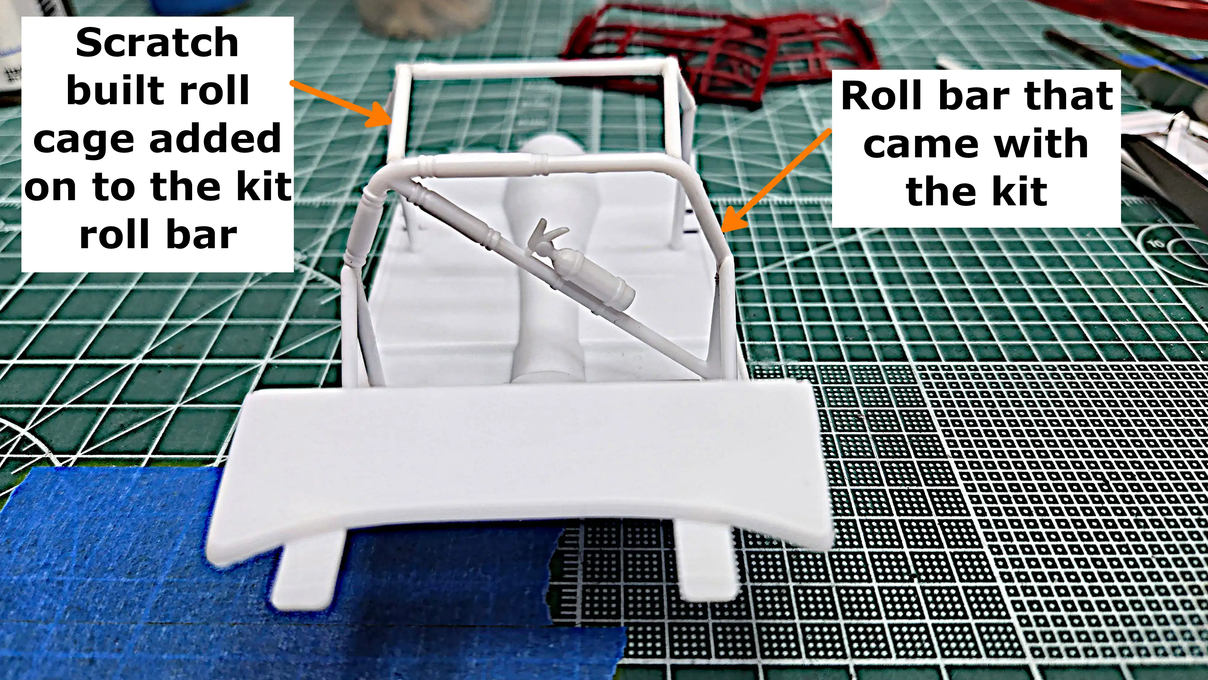
I scratch built a roll cage. I had tried to
use the premade roll cage from the Tim Richmond
Folgers Chevy Monte Carlo NASCAR; however, it
just didn't fit. And, it was an overkill for
the late model dirt track series. I used the
roll bar that came with the kit and built on
to it using Evergreen 212 0.080"/2.0mm rod.
This photo is looking at the left side as it was
built on the frame and floor pan. The joints
will be filled and made to look like welds.
The next couple of pictures are of the roll
cage from different angles.
I scratch built a roll cage. I had tried to
use the premade roll cage from the Tim Richmond
Folgers Chevy Monte Carlo NASCAR; however, it
just didn't fit. And, it was an overkill for
the late model dirt track series. I used the
roll bar that came with the kit and built on
to it using Evergreen 212 0.080"/2.0mm rod.
This photo is looking from the back as it was
built on the frame and floor pan. The joints
will be filled and made to look like welds.
The next couple of pictures are of the roll
cage from different angles.
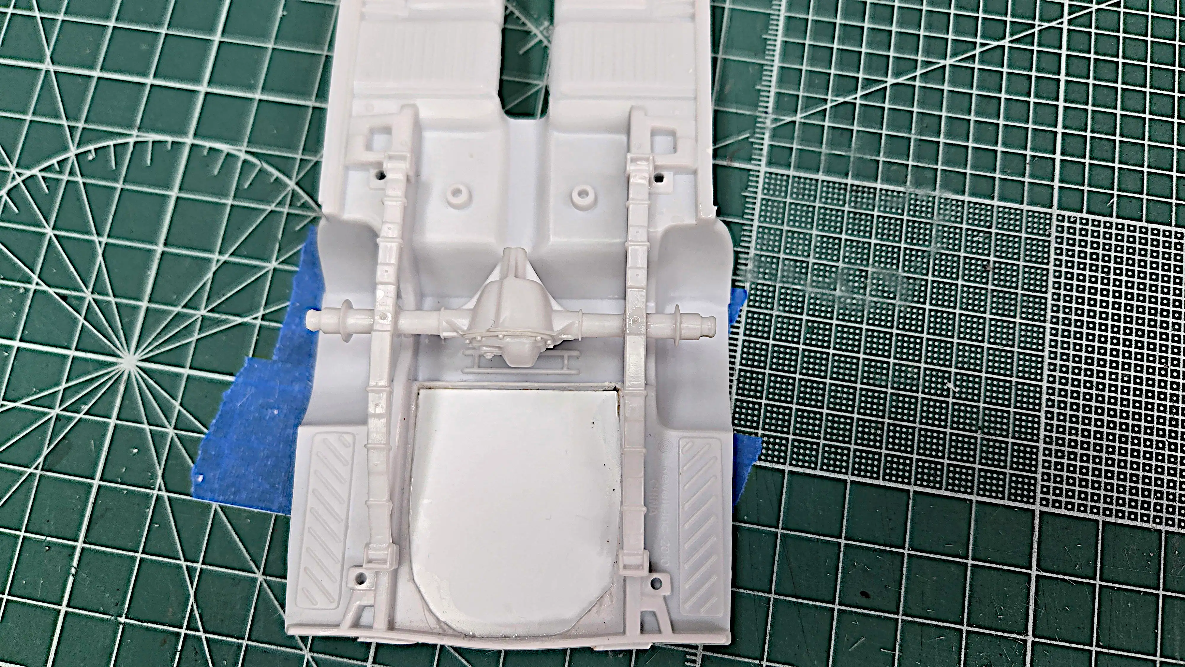
The differential and the rear leaf springs are
installed. I installed them because at the time
I thought they were going to be the same color
as the floor pan and frame; however, since, I've
changed my mind and will be making the
differential, Steel color and the leaf springs
Magnesium color.
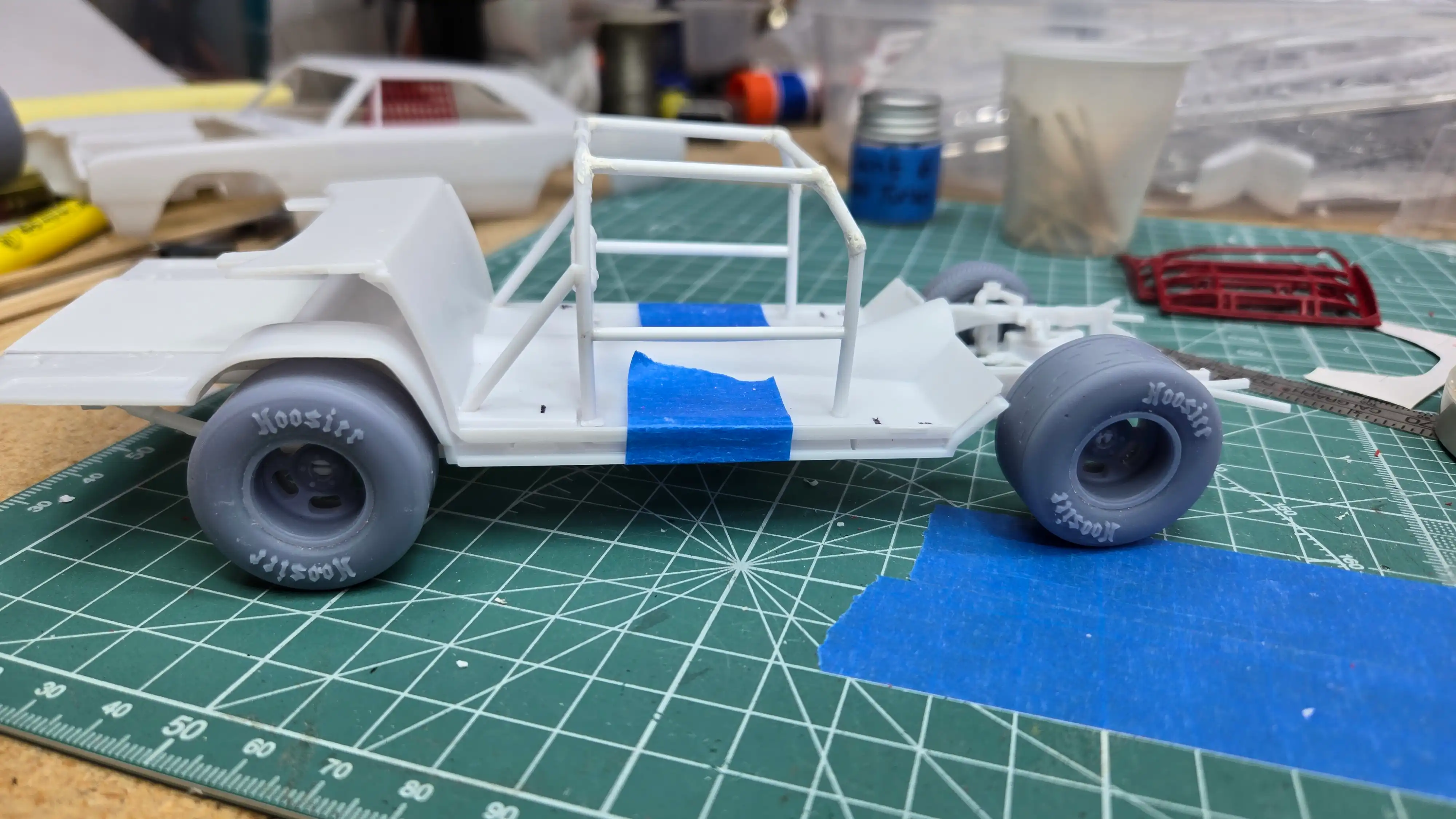
Front view of frame showing the stagger
for short track dirt racing. The inset
is a brief method for calculating the
stagger based on track corner radius and
size. There is much more to consider,
but I though this inset would give viewers
who are interested a tickler to do more
research on this topic.
Some of the parts have been primed using Vallejo
74.615 USN Light Ghost Grey Primer. I find this
primer works great with Vallejo paints and with
Tamiya acrylic paints; therefore the parts shown
will be painted with either Vallejo and/or Tamyia.
The spoons in the photo have been primed with
Mission Models MMS-001 Black primer and Mission
Models MMS-003 Grey primer, and I already used
too much thinner. [I] find Mission paints to be
very 'touchy'. The reason I'm planning to use
Mission paint is because I would like to paint
the body, Burgundy and the interior, Beige. The only
water based, acrylic, Burgundy paint I could find
was Mission Model Paint MMRC013. I also didn't
want to mix the burgundy color so I thought I'd
use the Mission paint, even though [I] think it's
very touchy to use. I want to see the finished
colors on the different color primers. I didn't
have Mission Models white primer, but that's Okay.
I think the gray is light enough to give me a good
idea of the look.
NOTE:
I've used Mission Models Paint before and when it
works, it works really well, and when it don't, it
don't. According to their website, the paint
chemistry is such that their thinner/reducer,
their primer, and their polyurethane mix additive,
add to the chemistry of the paint to make it work.
So...we'll see what happens.
Unlike the previous photo, this photo shows
all the parts in Vallejo primer. After
attempting to use the Mission Model beige
and burgundy, it confirmed my dislike of
Mission Model Paints. For more information
on my decision to scrap using Mission Model
paint see my
Build Information Page.
I spent quite-a-bit of time determining how to
mount the Slant 6 Hemi Head Turbo engine,
(AKA - The Leaning Tower of Power).
What I thought was going to be a challenge,
turned out to be quite easy.
I didn't think I'd be able to use the engine
frame supports that are molded in as part of
the frame, therefore, I mocked up the front end
of the car and positioned the engine in the
engine bay. When I had the engine in position,
I noticed that the frame mounts lined up with
a part of the engine I could easily install
some sort of motor mount. I measured
the distance from the engine to the frame mounts
letting me know the length that the engine
mounts would need to be to catch hold of the
frame mounts. I then marked the engine using a
sharpie as to where the mounts should be
installed. Now...what will I use for the mounts?
The engine mounts on the frame are grooved so
that points on the kit engine would slide into
the groves. I figured that all I should have to
do is add some square stock to the engine that
would lay into the slots in the frame. I looked
in my stash and found some rectangular rod. The
rod is from
Plastruct
#90745 Cat No. MS-410, 0.040" x 0.10"/1mm x 2.5mm.
This will be perfect. I cut two small pieces of
the rectangular rod, 4mm long for the right side
of the engine and 3mm long for the left side of
the engine. I then glued them to the engine
block at the locations I previously marked.
This photo and the next several photos show
these mounts glued into position. The will
be painted Tamiya XF-1 Flat Black.
The Slant 6 HEMI Turbo concept engine from
VCG Resins
is a really nice engine; however, it
does not come with a fan. I used the fan from
the kit engine. I trimmed the mounting shaft
of the kit fan so it would fit behind the
radiator, painted it with Tamiya X-1 Black, and
glued it to the fan pulley.
This view also shows the fuel input piping
from the turbo charger to the input injectors.
You can also see that the valve cover by the
#1 plug is chipped. I fixed this chip after
taking the picture. It always amazes me the
multitude of sin that is exposed in a photo.
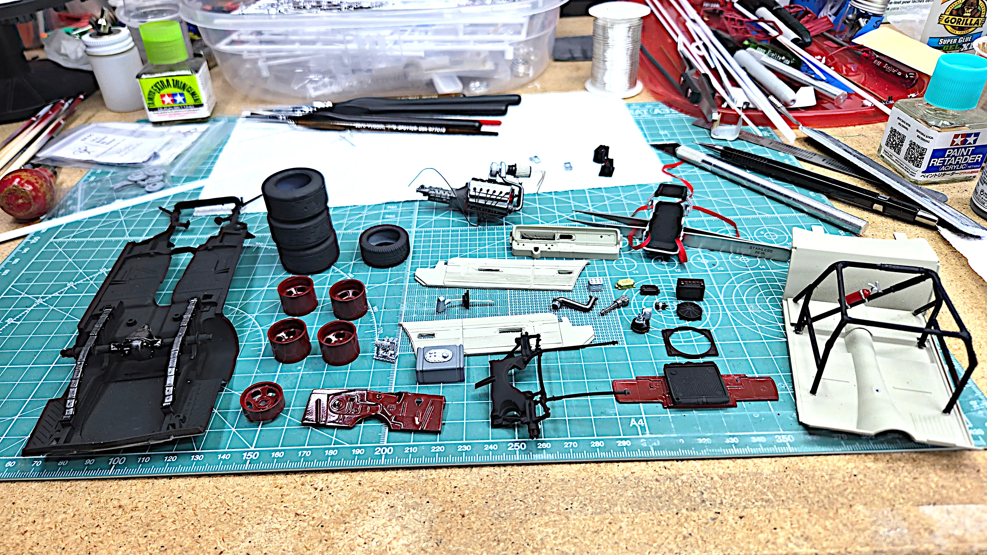
Most, if not all of the parts have been painted.
I'm sure there will be some small parts that
still need paint and I'm also sure there will be
some touchup here and there.
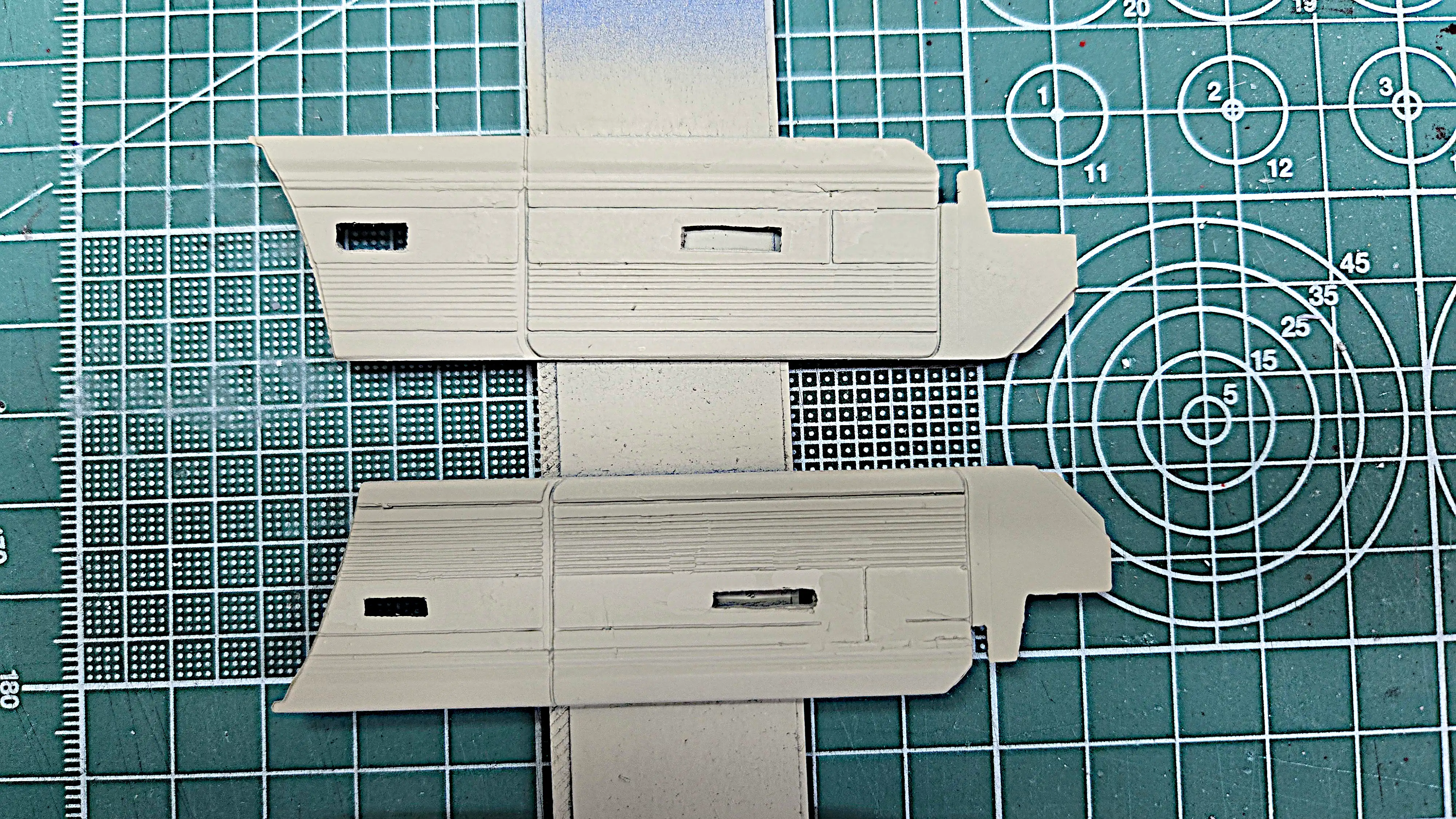
The interior door panels are painted. I cut
the arm rests out because they would have been
removed on an actual stock car.
I wasn't going to use the interior side panels;
however, the dashboard mounts and without them
there wouldn't have been enough support to hold
the dashboard in place.
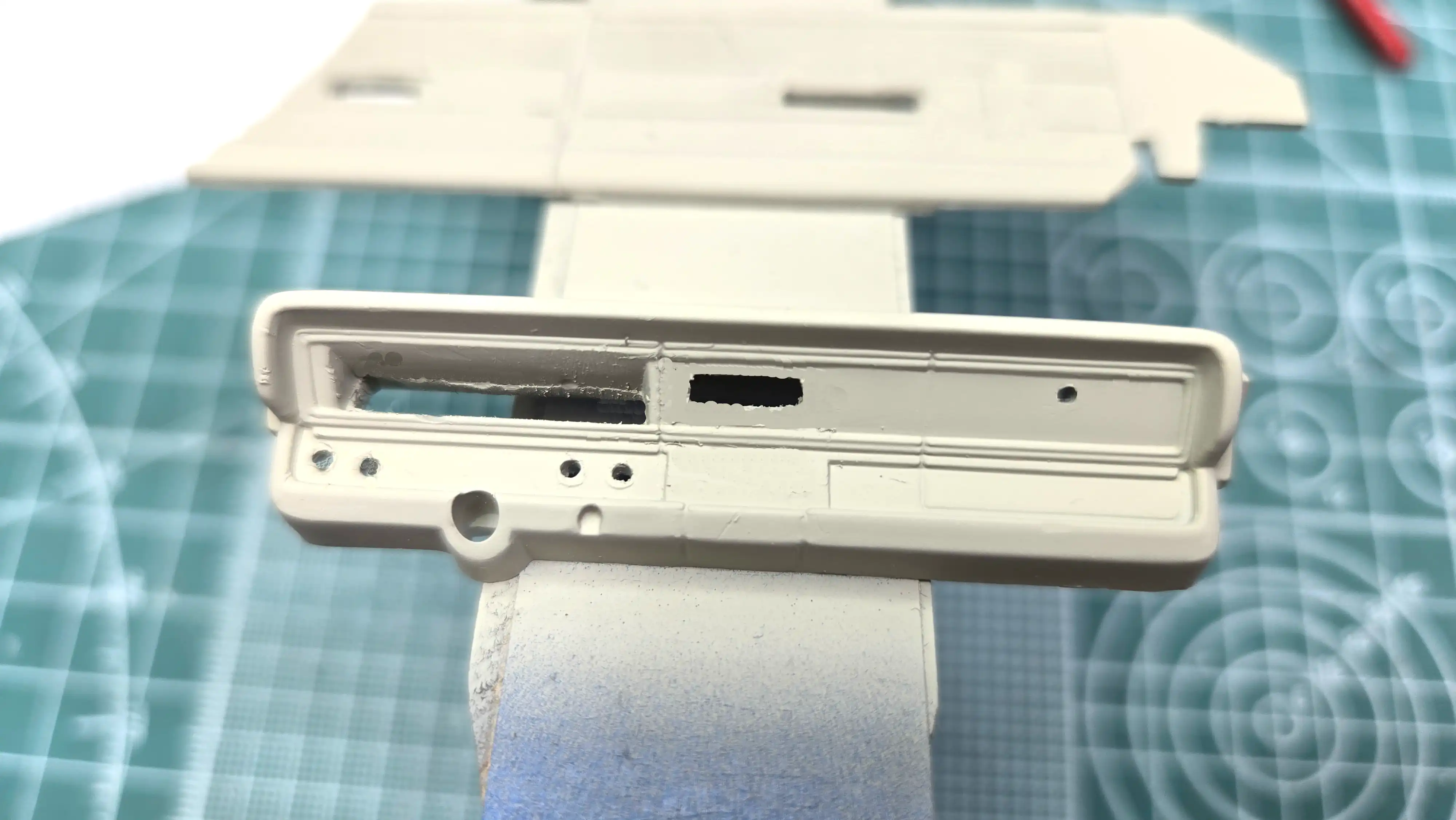
I cut the instrument cluster from the dashboard.
I also cut the radio out and drilled the
locations for dashboard controls and the
glove box latch. These all would have been
removed from the stock car. There is no need
for instrumentation because for short track
dirt racing the car will do less than 50-laps
at most events, and the driver wants to go
as fast as possible not caring about fuel
level, oil pressure and alternator indicators.
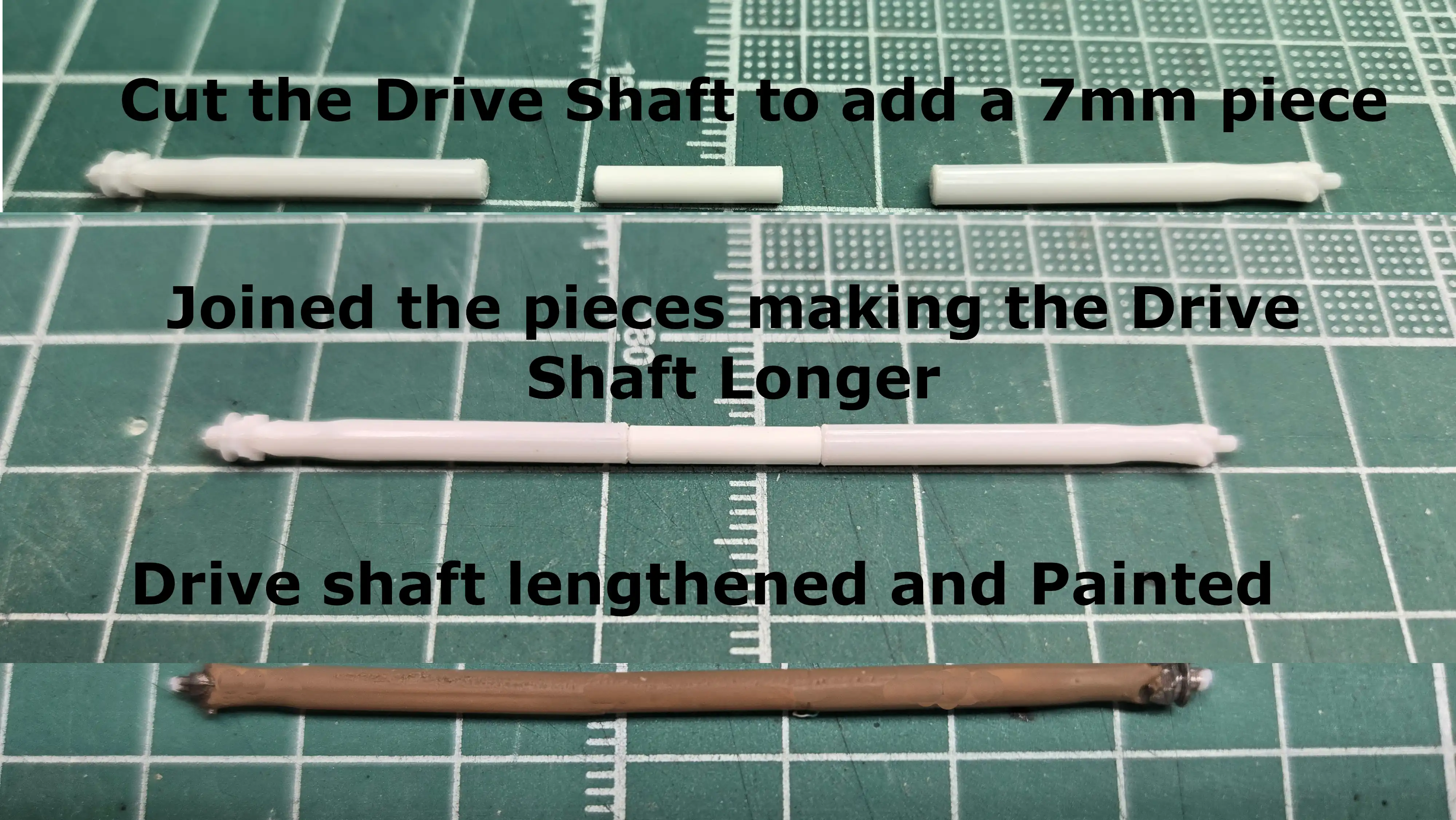
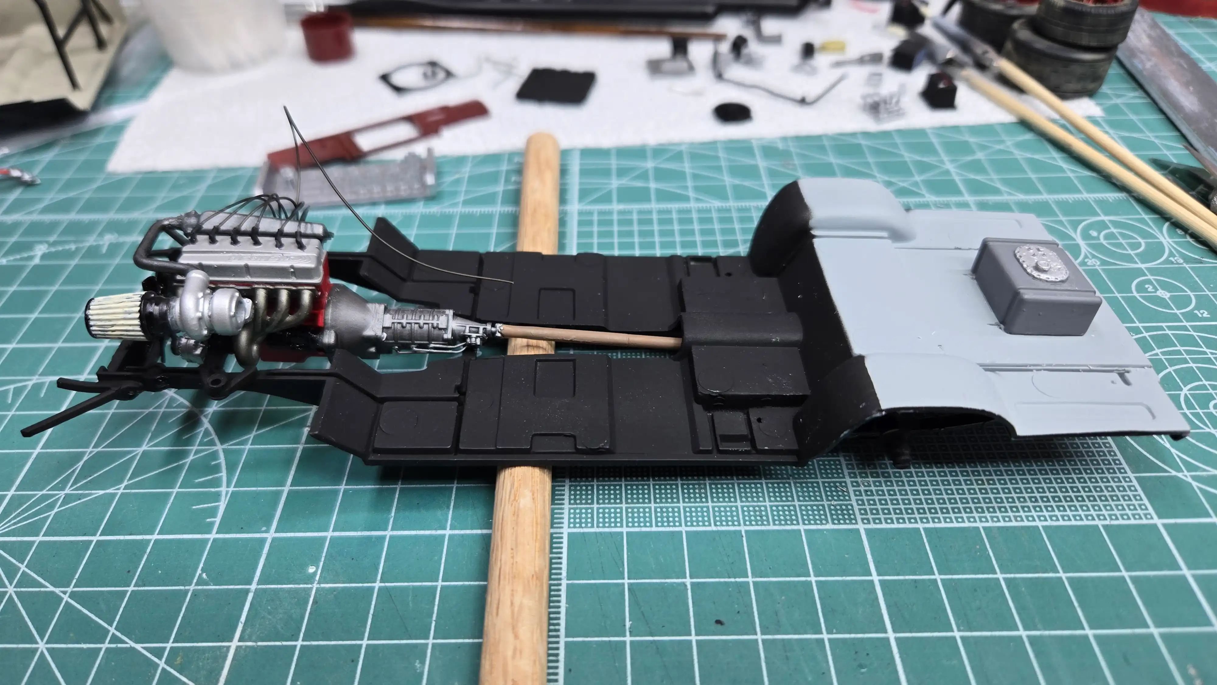
The transmission of the slant 6 HEMI turbo is
not as long as the HEMI that came with the kit.
Therefore, the drive shaft was too short and
had to be made longer. This photo shows the
process of elongating the shaft.
I cut the driveshaft
in half and added a 7mm long piece of
Evergreen 2mm Rod in between. I didn't fuss
too much. I simply sanded the the joints to
make them disappear and then painted the
driveshaft with Tamiya XF-52 Flat Earth. The
universals on each end are painted with
Vallejo 77.712 Steel.
This photo shows the body after painting.
I wanted to make the body burgundy. The
only burgundy water based acrylic I could
find was from Mission Model Paints MMRC-013.
I bought the paint from Ebay and the day
it was delivered the outside temperature
was 8°F. (We, here in eastern PA were
in the middle of a very cold snap.) I left
the paint set for several days before using
it and then mixed it with Mission thinner
and Mission Retarder. I shot some on a test
spoon that was primed with Mission Model
primer. The paint was redish coming out of
the bottle; however, it was almost clear
coming out of the airbrush. I tore down my
airbrush and thoroughly cleaned it. I then
made the correct mixture again and shot
another test spoon. The paint was still
almost clear with just a slight pink hue.
That's when it hit me, I bet the paint
had been frozen or, if paint doesn't freeze,
the cold might have broke down the paint
chemistry.
I'm actually glad that happened. I've never
been a big fan of Mission Model Paints.
There is nothing wrong with them, [I] just
don't like them. I did some research online
as to what colors make burgundy and found
that a mixture of the three primary paint
colors - red, blue and yellow will make
burgundy. I used Tamiya X-7 Red, X-4 Blue
and X-8 Lemon Yellow. The online
recommendation was a ratio of 8 parts
red to 4 part blue to 1 part yellow.
Using that ratio, the color wasn't what I was
looking for. I started playing around with
different ratios and found that 10-parts
of X-7 Red, to 1-part of X-4 Blue, to
3-parts of X-8 Lemon Yellow gave me the
shade of burgundy that I wanted. The final
color can be seen on the body in this photo.
At the Nazareth, PA 1/2-mile dirt oval it was
required to run Hoosier on the late model class.
I found 3D printed Hoosier tires at
MCV Products.
Full Set 15" Old School Slotted Mags with Strip
Tires, MCV-W5. I painted the tires with Tamiya
XF-85 Rubber Black and the wheels are done in the
burgundy body color. The tires and wheels are
assembled and I'm starting to dirty them using
Tamiya Pastels.
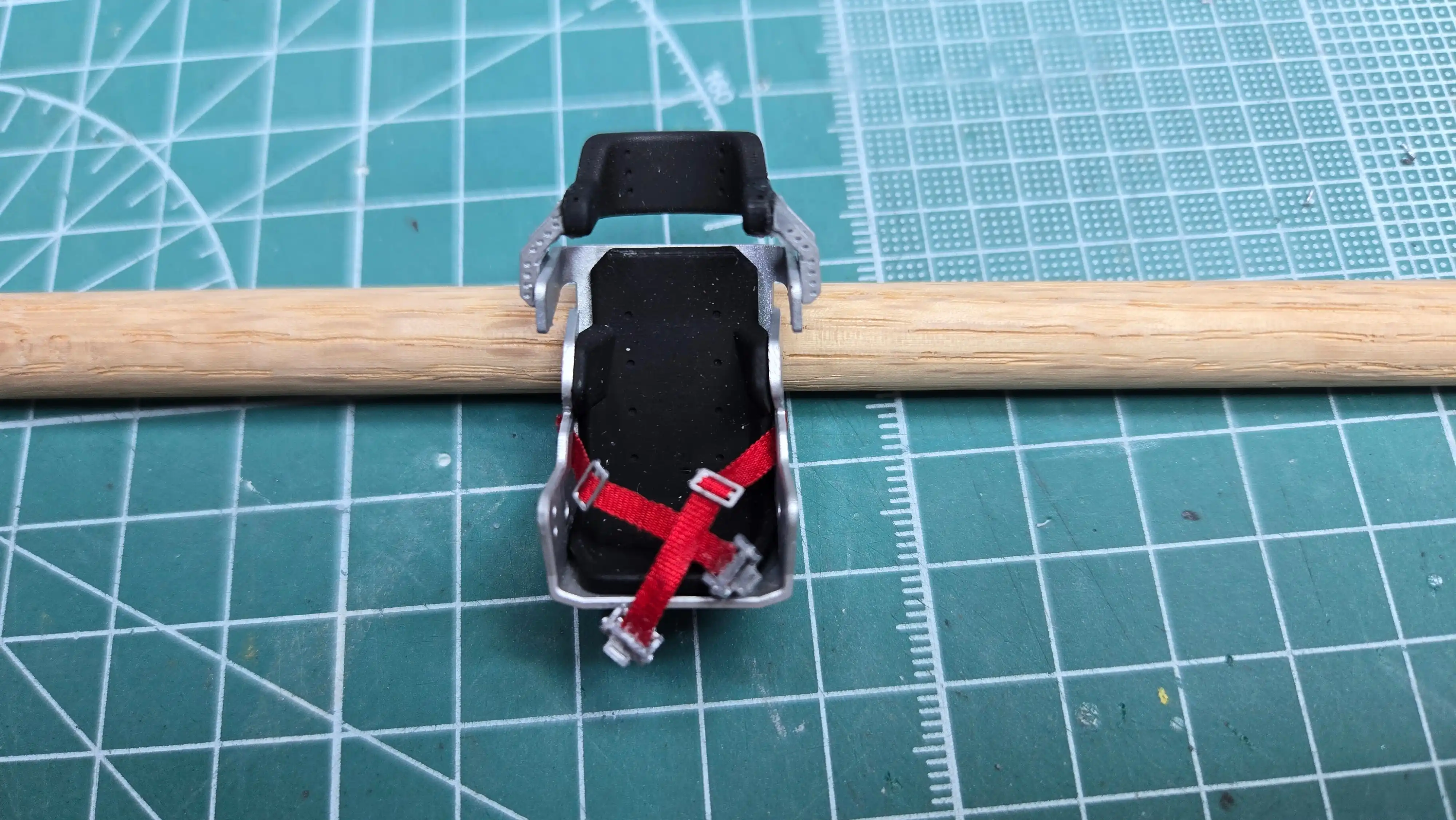
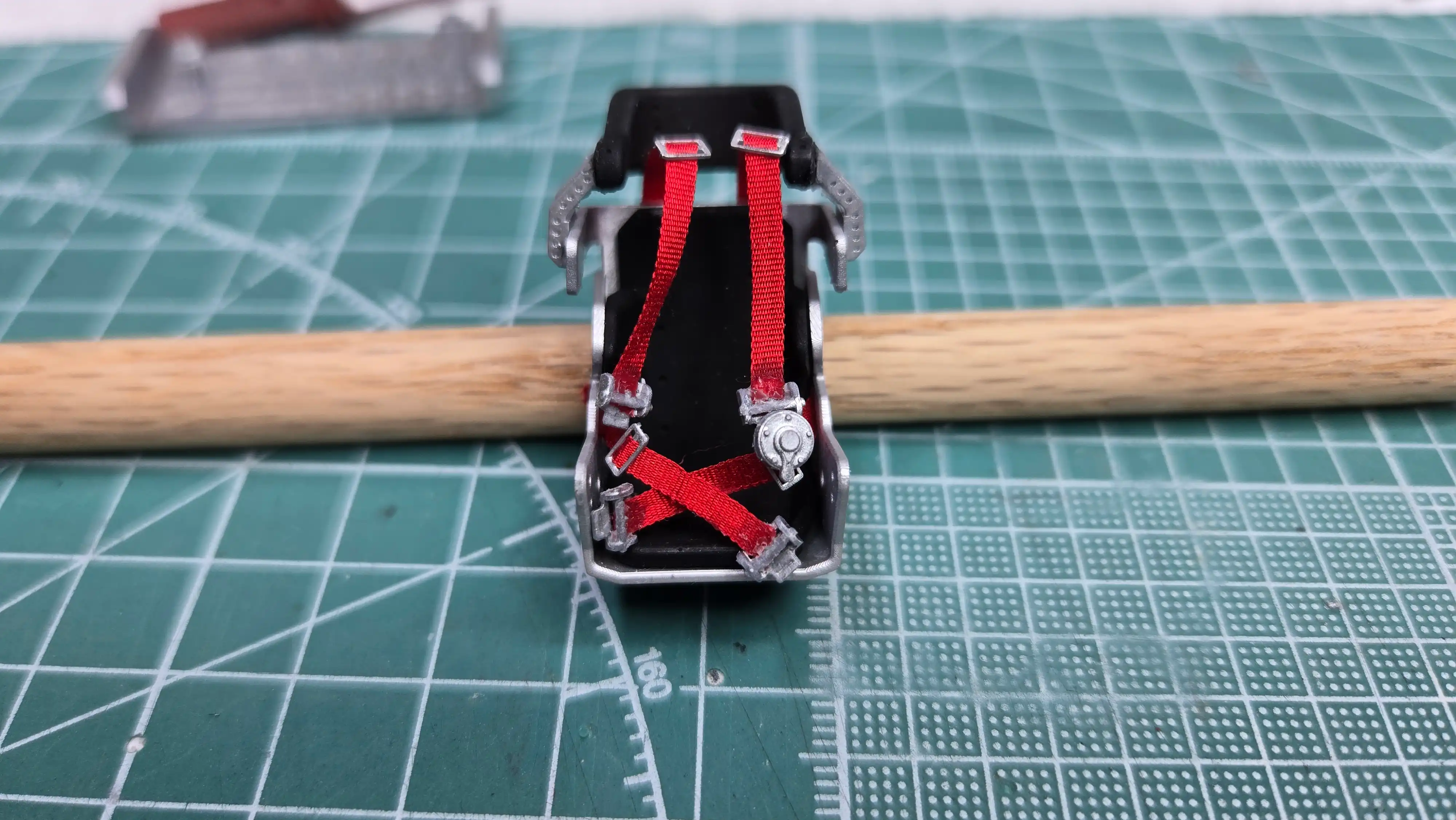
This photo shows the racing seat assembly in
progress. I bought the seat and the belts from
MCV Product.
The racing seat is part number
MCV-S1 and the Quick Release seat belts is
part number MCV-SB1.
These are great products; however, I must say
that the installation of the belts, buckles
and misc. clips is difficult for an old guy
like me. A steady hand is required. I struggled
with them because I'm a-bit shaky, but it was
well worth the time. They work and look great!
There will be another photo of the seat when
the shoulder straps are installed.
While the glue was drying on the seat and belts,
I dry fitted the slant 6 HEMI Turbo into the
frame for about the third time. There will not
be a lot of room in the engine compartment
with this engine installed, but I'll cross that
bridge when I get there. When zoomed in notice
that I have the firing order correct.
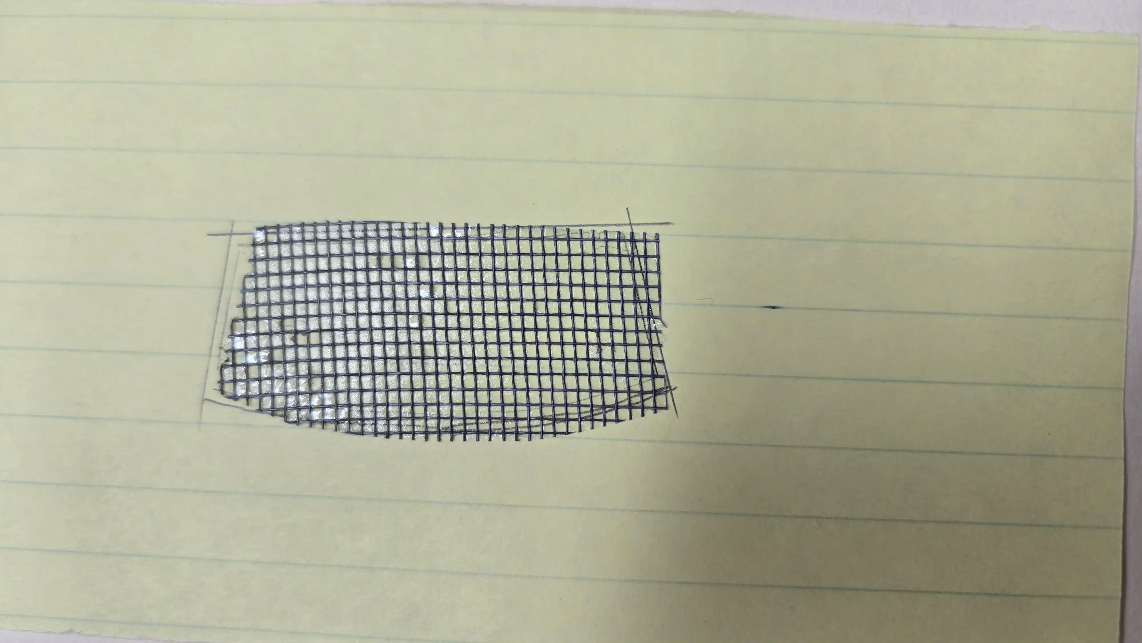
Many late model short track stock cars removed
all the glass and then replaced the windshield
with fencing screen. This photo shows a rough
cut piece of the screen I plan to use.
I struggled with what to use for this screen. I
search my locale hobby shop;
Trains & Lanes Hobbies
but couldn't find anything that would work. I
was looking for a wire fence with openings in
the full size range of 1" to 2"/25.4mm to
50.8mm (in 1:25 scale 0.040" to 0.080"/1mm to
2mm) square or rectangular. Since I couldn't
find anything I decided I could make my own.
I drew a grid with 2mm x 4mm rectangles and was
planning to use 26AWG solid wire to make the
screening. The more I thought about it, the
more I realized how crazy that would be. I
then started searching through Home Depot and
Lowes for some ideas and decided to use screen
door/window patches. The one shown has
openings of 1mm x 1mm. This is equivalent to
0.975" x 0.975" in 1:25 Scale. So...that's
what I'll be using for the windshield
and most likely in place of the front grill.
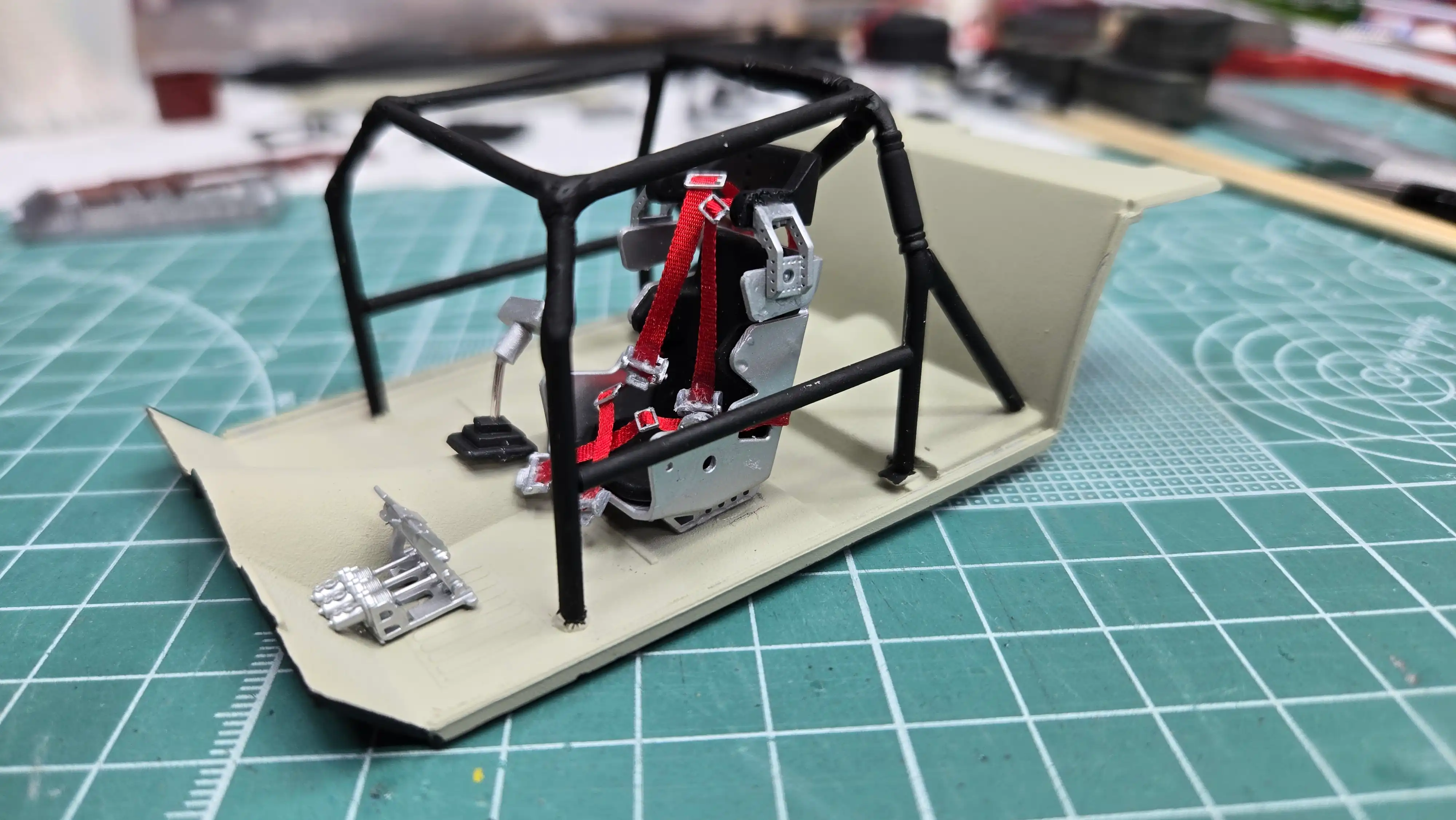
I have the racing seat, lap and shoulder belts
finished. The seat and belts came from
MCV Product.
They look great! For an old shakey
guy like me, the belts were a tough install.
But well worth the effort.
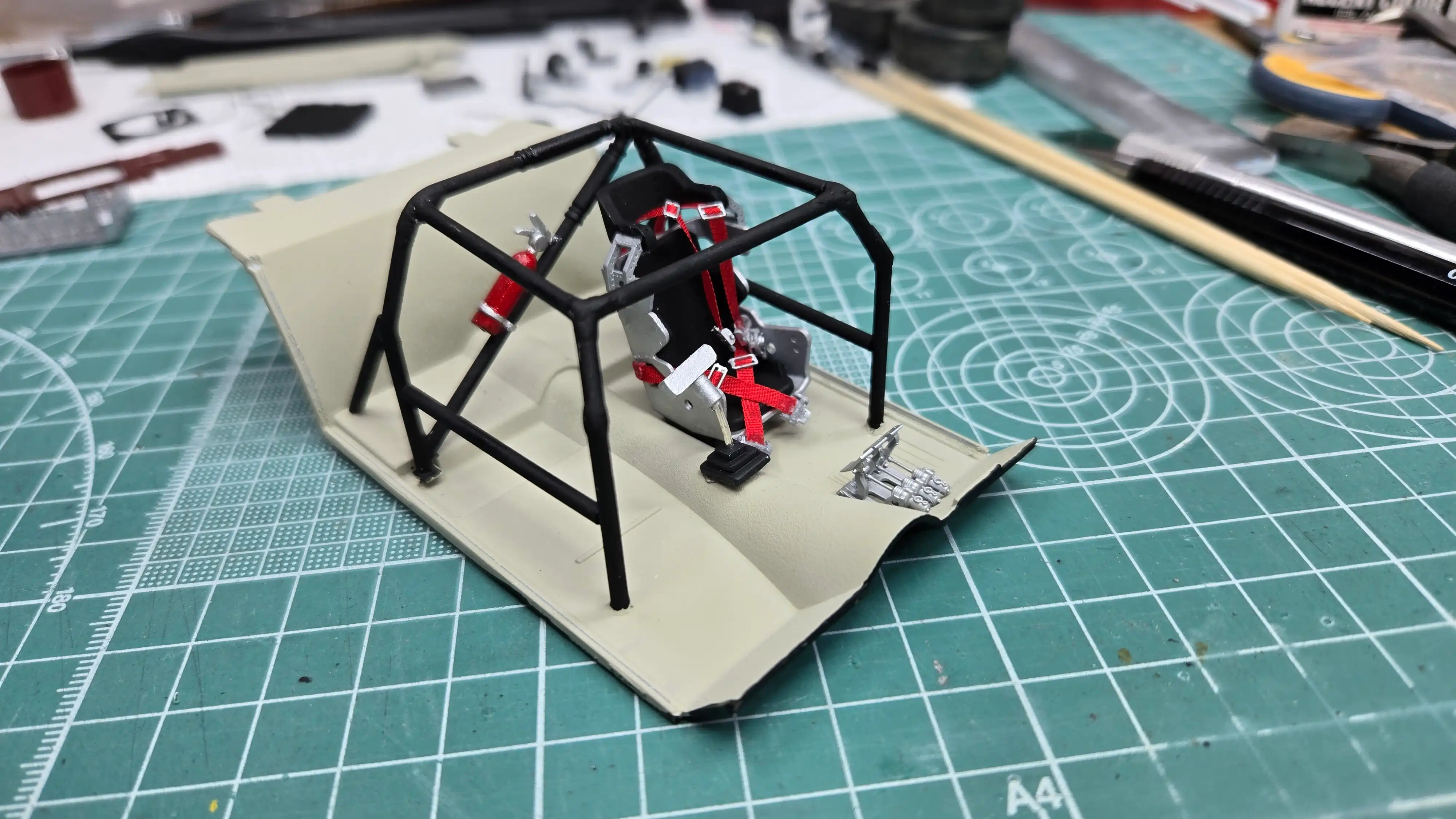
This is a left side view of the interior floor
pan. I do have to fix the shifter boot to the
floor fit. Since this photo was taken I also
think that the battery will need to be installed
in the interior. There is just no room in the
engine compartment after putting the slant 6
HEMI Turbo on the frame. I might even have to
mount the brake master cylinder and booster
under the car. We will see.
This is a right side view of the interior floor
pan. I do have to fix the shifter boot to the
floor fit. Since this photo was taken I also
think that the battery will need to be installed
in the interior. There is just no room in the
engine compartment after putting the slant 6
HEMI Turbo on the frame. I might even have to
mount the brake master cylinder and booster
under the car. We will see.
This is a front view of the interior floor
pan. I do have to fix the shifter boot to the
floor fit. Since this photo was taken I also
think that the battery will need to be installed
in the interior. There is just no room in the
engine compartment after putting the slant 6
HEMI Turbo on the frame. I might even have to
mount the brake master cylinder and booster
under the car. We will see.
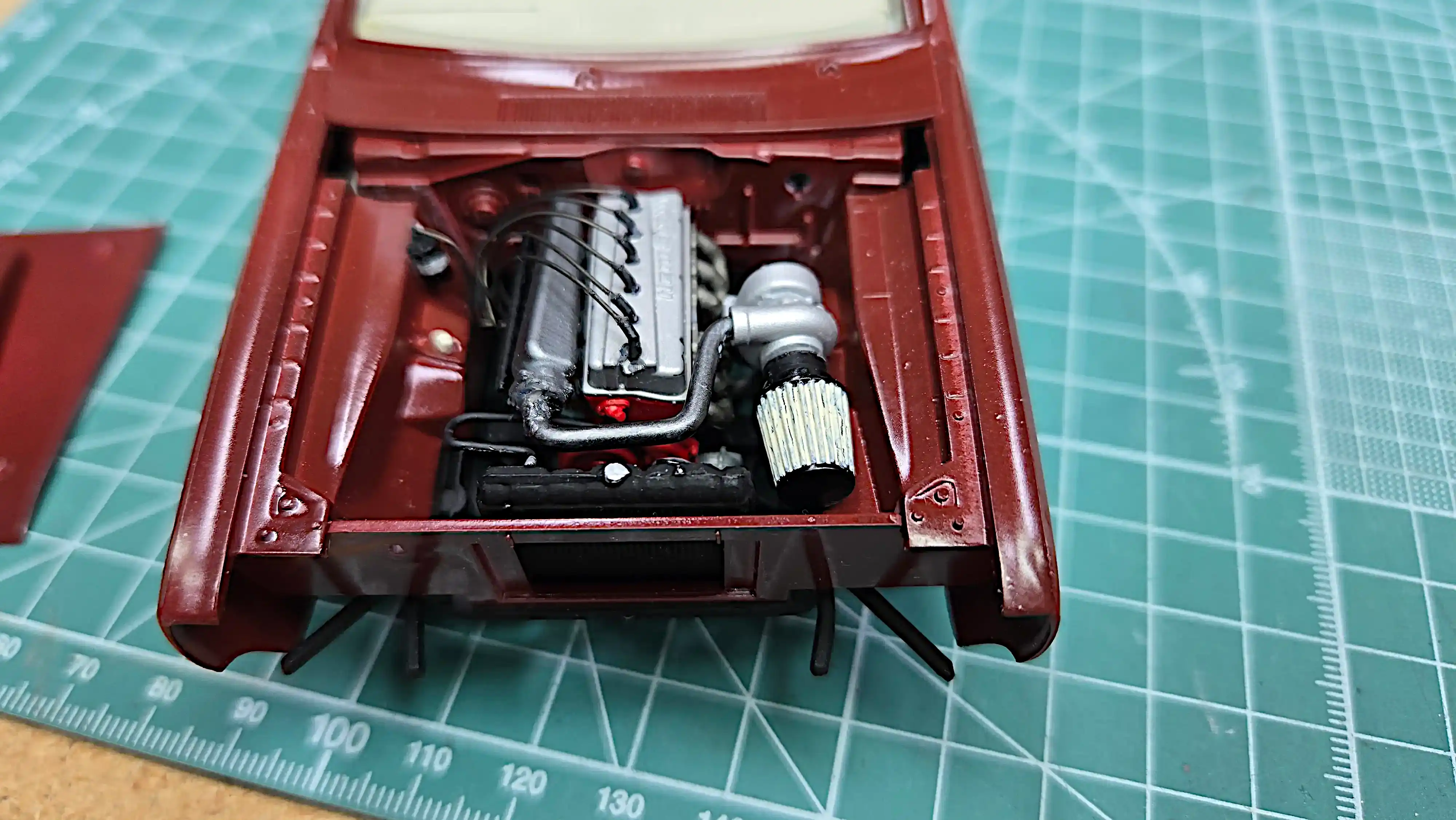
The Slant 6 Hemi Turbo Charged concept engine,
and drive shaft are installed. There isn't
going to be much room in the engine compartment
when the body is put in place. It's actually
looking like the battery might have to go in the
interior and the brake master cylinder might have
to be placed under the floor. More about this
later.
The fuel cell is also mounted on the trunk floor.
The hold down straps are not installed yet and I
might build a crash protection around it,
but I'm not sure about the protection because I'm
not sure what I'm going to do for a rear bumper
yet. If I decide to use the rear bumper that came
with the kit I'll need crash protection. If I
decide to make a tubular front and rear bumper
I won't need the fuel cell protection.
I used 26AWG (American Wire Gauge), bare soft
drawn wire to make hold-down strapes for
the fuel cell. I painted the wire with Tamiya
XF-16 Flat Aluminum just to take the shine off
of the wire.
I added hold-down clamps to the battery. I
used two small pieces of Evergreen 262
(0.080"/2mm) channel for the clamp and cut
each one approximately 5mm long. I painted
the channel with Tamiya XF-16 Flat Aluminum.
I then used 26AWG (American Wire Gauge)
soft drawn titanium plated wire for the
hold-down rods (titanium planted because
that's what I had). The wire used for the
hold-down rods has not been trimmed in this
photo.
There is absolutely no room under the hood to
mount the battery. At first I thought I would
just leave the battery out, but than I decided
I'd place it the interior and run the wires
through the firewall. I wanted to protect the
driver as much as possible, so I mounted the
battery under the dash-board on the the
passenger side of the car. You won't be able
to see the wires when everything is assembled.
In fact, once the body is placed on the frame
I doubt the battery will be seen.
Closer view of battery mounted under the
dashboard.
There is absolutely no room under the hood to
mount the battery. At first I thought I would
just leave the battery out, but than I decided
I'd place it the interior and run the wires
through the firewall. I wanted to protect the
driver as much as possible, so I mounted the
battery under the dash-board on the the
passenger side of the car. You won't be able
to see the wires when everything is assembled.
In fact, once the body is placed on the frame
I doubt the battery will be seen.
Front view of the battery mounted under the
dashboard. The gap in the dash-board was
fixed, but as you can clearly see, opened
again. It will be fixed...again.
There is absolutely no room under the hood to
mount the battery. At first I thought I would
just leave the battery out, but than I decided
I'd place it the interior and run the wires
through the firewall. I wanted to protect the
driver as much as possible, so I mounted the
battery under the dash-board on the the
passenger side of the car. You won't be able
to see the wires when everything is assembled.
In fact, once the body is placed on the frame
I doubt the battery will be seen.
When the interior tub is placed in the body,
there was a gap between the body and the
tub. This gap was approximately 1mm. I glued
a strip of Evergreen 148 (0.040" x 0.188" / 1mm
x 4.8mm) to each side of the tub to fill the gap.
I have the model mostly built. There are a
few things missing, such as:
Exhaust
Brake master cylinder/booster
Front and Rear bumpers
Trunk trim piece
Grill (Screen covered)
Ignition box(es)
Decals
The last thing will be to dirty the whole car.
I'll be using Tamiya pastels for most of the
dirt; however, if it ever gets warm enough,
here in eastern PA so the ground is not rock
solid (Feb. 20, 2025), I'll make some actual
mud. I mix actual ground with white glue and
brown paint and then just simply "dob" it on
in spots.
There are a few chips on the door shown, but
I'm leaving them as part of the usage of this
car on the track.
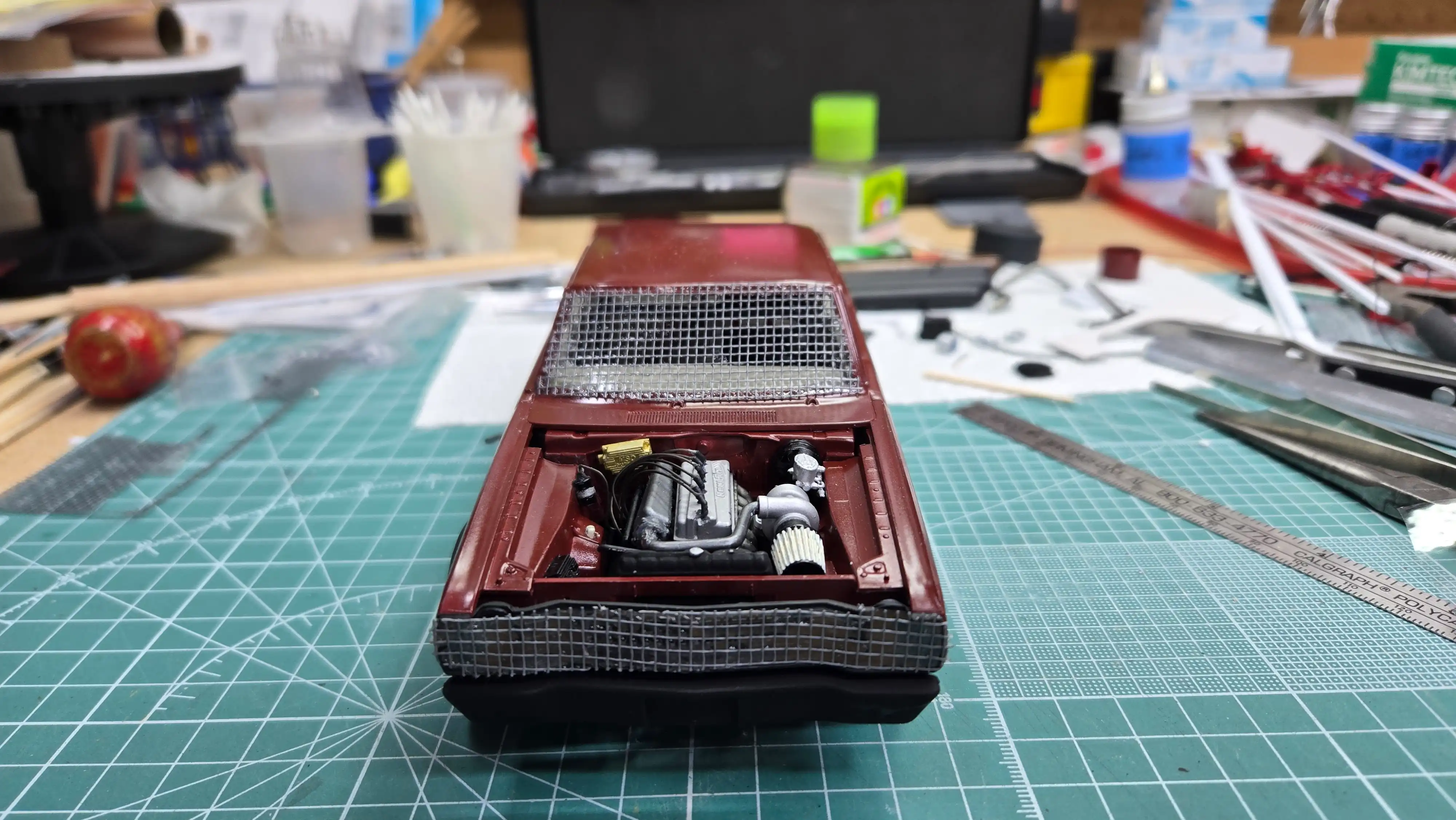
This photo shows a front view of the model.
I had to use the hood with the air scoop
and hole to clear the top of the slant 6
HEMI Turbo charged engine. There is still
no bumber or grill in place. I stripped the
chrome from the front bumper and painted
it with Tamiya XF-1 Flat Black. I'm currently
stripping the chrome from the grill and will
be covering that with the same screening I'm
using for the windshield.
The engine compartment is almost finished. I
still need to install the exahaust pipe onto
the Turbo charger exhaust side, mount the
brake master cylinder and booster and I'll
be adding two electronic boxes, one to the
firewall and one to the inside of the right
fender. They're all ready, I just haven't
glued them in place.
I cut the trunk lid open just to show the
fuel cell. I installed the hinges. The trunk
lid will slide onto the the hinges. I'll have
to mount a small magnet to hold it fully
closed. I also stripped the chrome off the
rear bumper and painted it with Tamiya XF-1
Flat Black. The trim panel is painted the
body color and it and the bumper will be
installed.
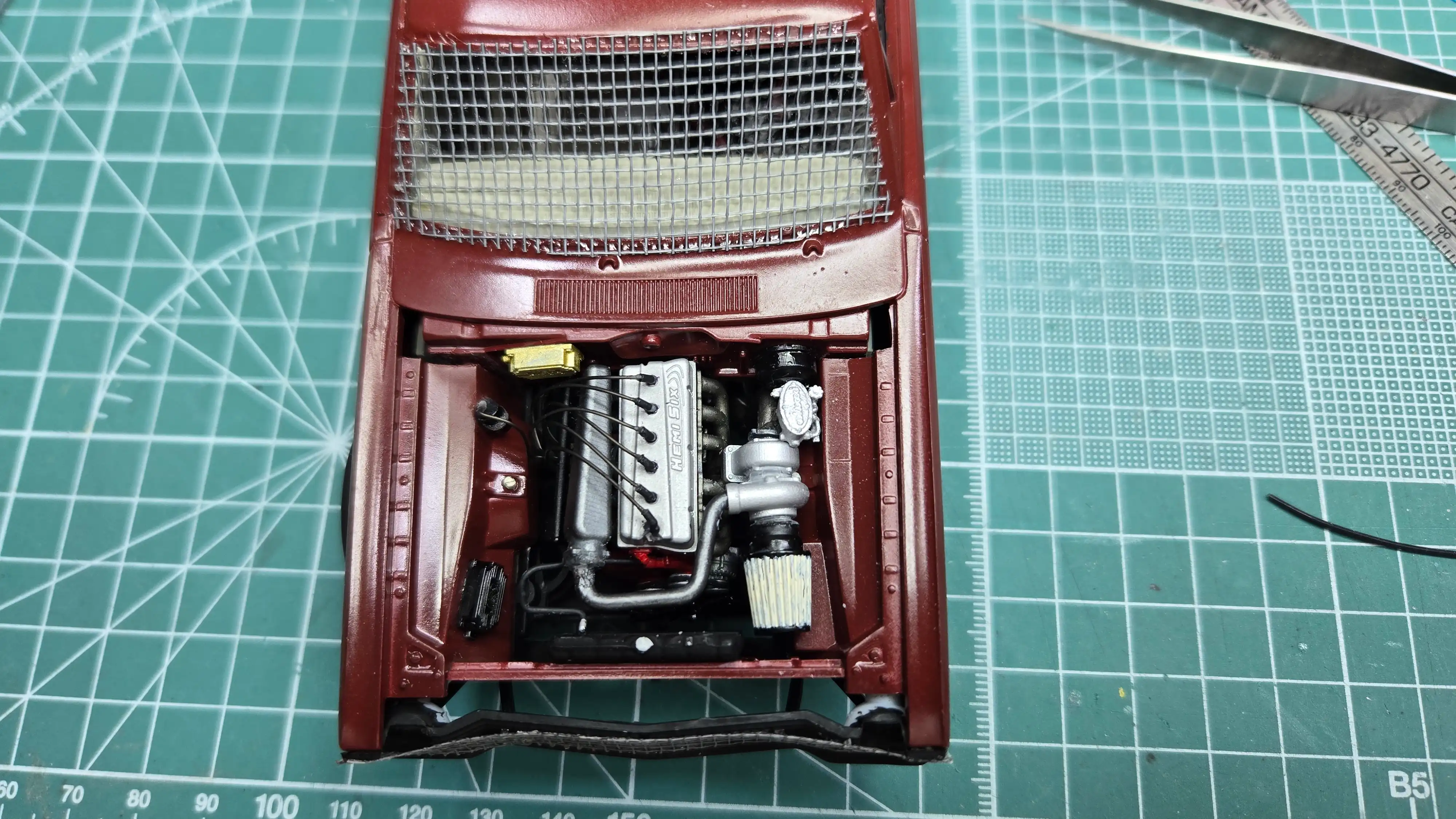
I used screen from a roll of screen door
repair as the windshield and also as the grill.
The screen has a sticky back and on this photo
you can see that there is still some residue
of the 'sticky stuff' in the screen openings.
You will see later that I did remove most of
it.
The engine compartment is finished with the
exception of applying some dirt. It was a
tight fit to place the brake master
cylinder, and as I stated earlier, there was
no way the battery would fit under the hood.
Although it can't be seen, the battery is
under the dashboard of the passenger side
of the car. I'm not happy with the radiator
hose. I think it's too small, but at this point,
I'm not going to change it. I might change my
mind later, but I doubt it.
I'm making my own decals so that I can have
local sponsors on the car. Because I'm making
my own, I load the images into
Gimp
- GNU Image Manipulation Program. Gimp is
a free photo editor very similar to Adobe
Photoshop. I then increase the resolution
and size them before placing them on water
slide printer paper. Because they are a
graphic in Gimp, I can take an image of the
car and copy and paste the decal images
onto the photo. This gives me an idea how
the car will look with the decals in place.
So...this photo IS NOT the car with actual
decals on it. It is an image of the car with
decal graphics copied to it.
These are the decals I'll be using. Only one
of each is shown in this photo, but there
will be duplicates so both sides of the car
will have decals. I wanted to make my own
decals so that the sponsors would all be actual
local businesses in Nazareth, Pa and surrounding
communities.
My Logo - Will be placed on the rear
quarter panels
Hoosier - Will be used because they are
a sponsor of the race track and all cars
display their logo
Nazareth Food Bank - will be placed on the
front quarter panel
The numbers will be used on the doors,
roof and trunk
Nazareth Diner
ELS - East Lawn Plumbing Supply
The Key - A local newspaper will be used
Tuscanna Pizza & Pasta
Breidinger's Speed Shop
Birthright Brewing Co.
Driver signature - Although I didn't
actually drive, in the model world I can
be the best driver ever

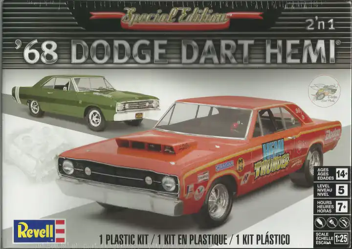 1968 Dodge Dart Hemi Box Art
 Examples of some late model stock cars
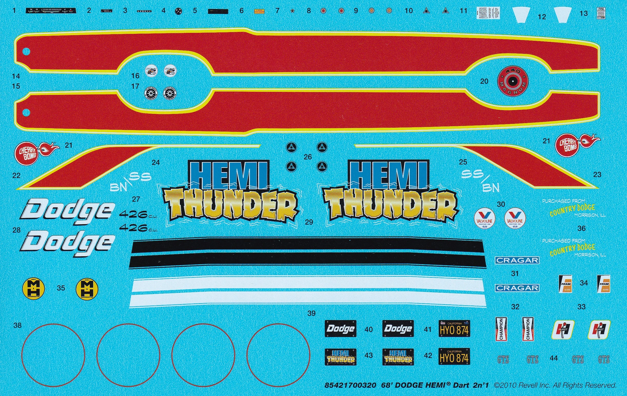 Decal Sheet
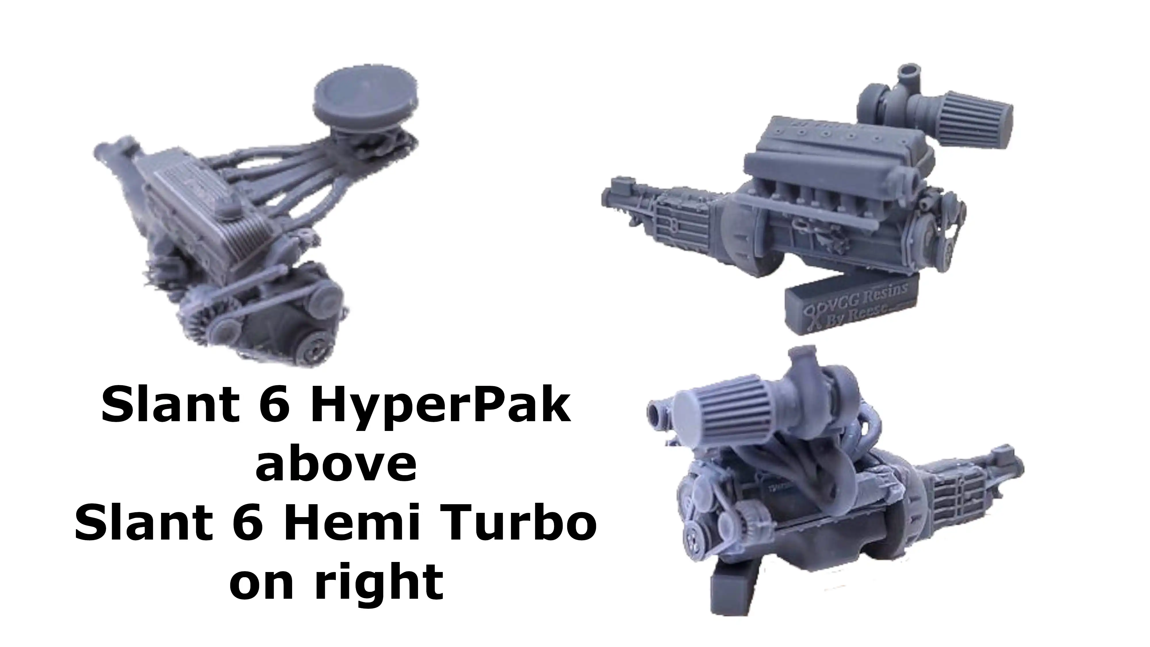 Two different Slant 6, 3D printed engines, one
HyperPak and one Hemi Turbo
Two different Slant 6, 3D printed engines, one
HyperPak and one Hemi Turbo
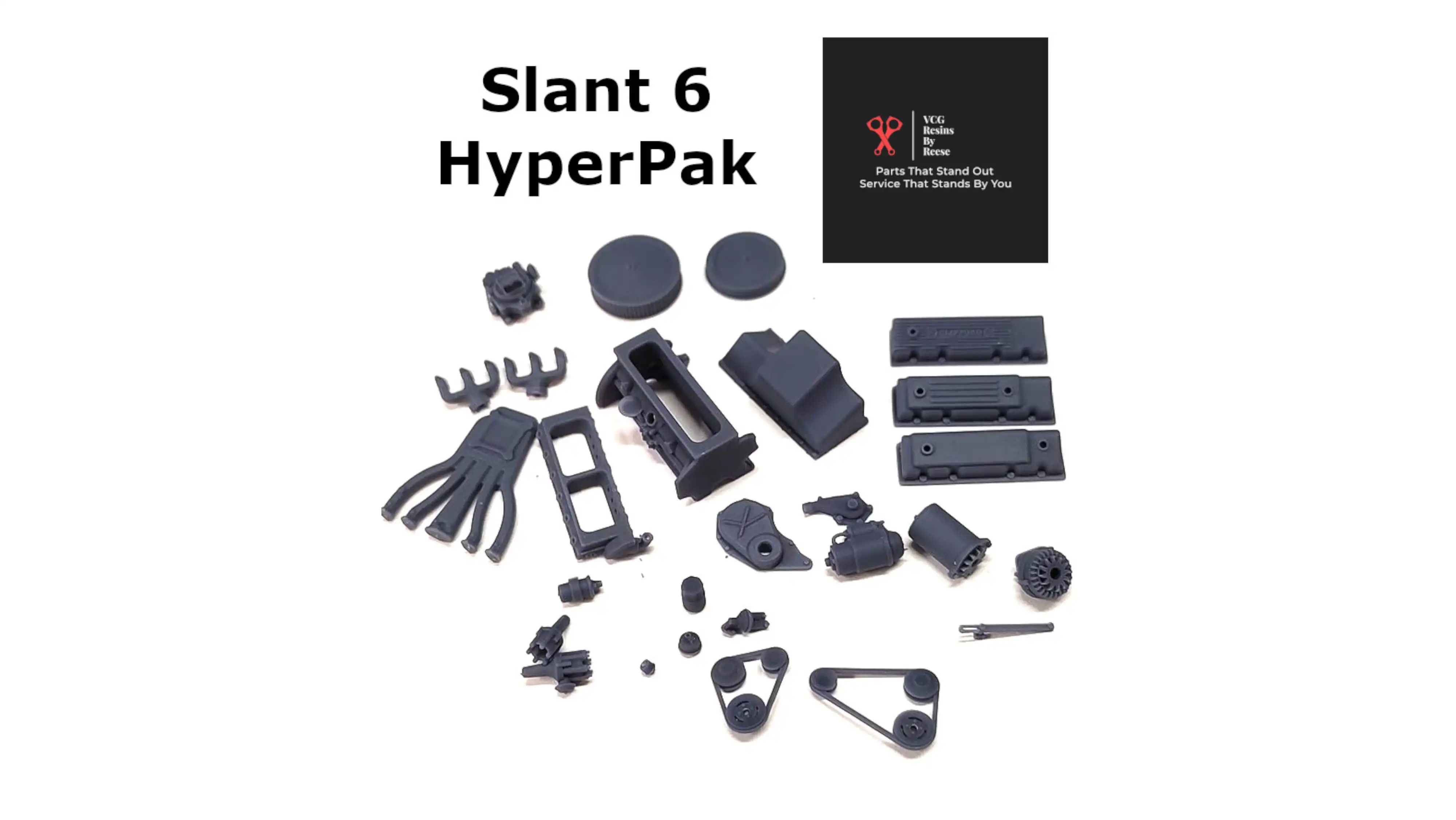 VCG Resins Slant 6 HyperPak Engine Parts
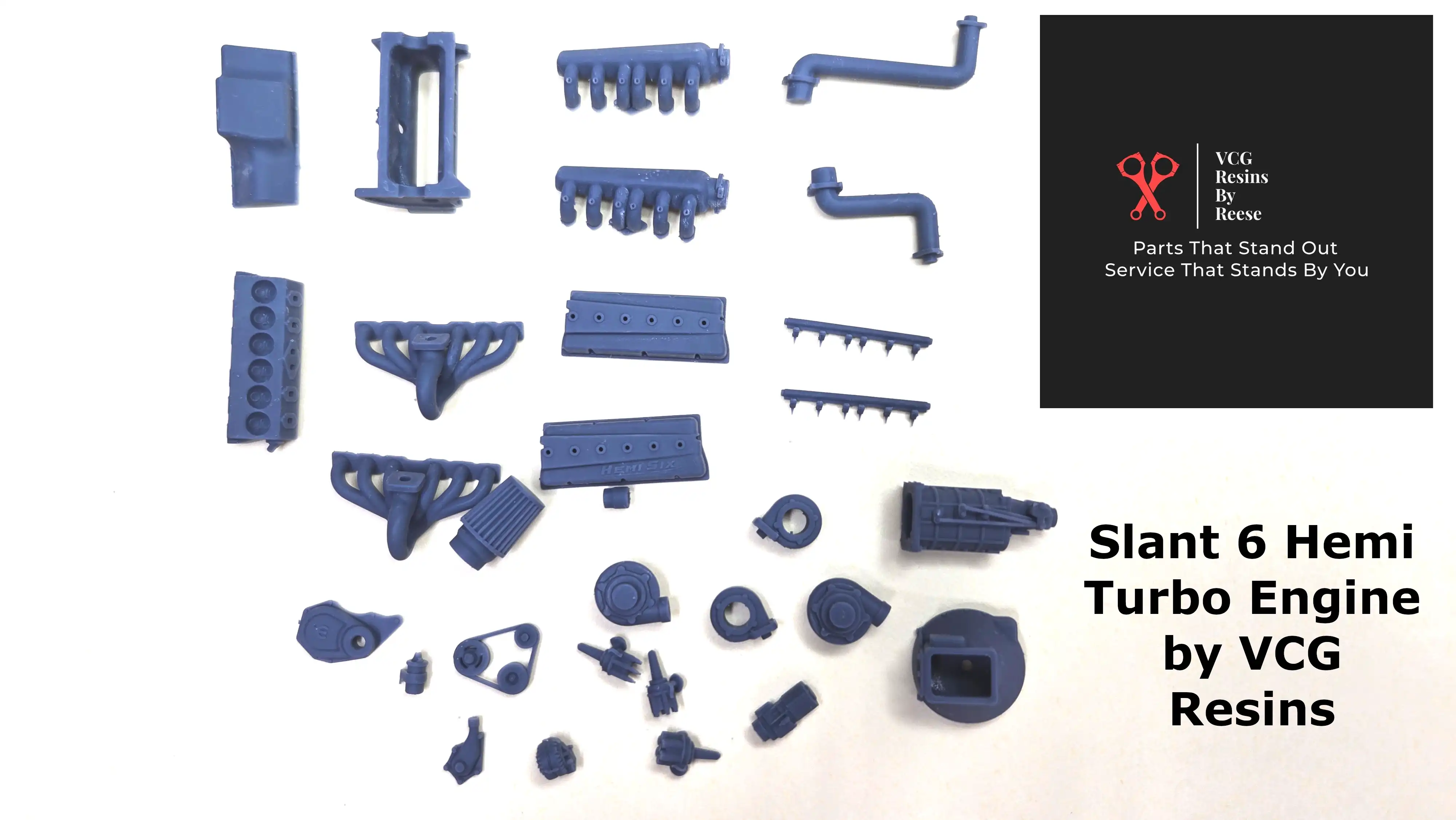 VCG Resins Slant 6 Hemi Turbo Engine Parts
 VCG Resins Slant 6 HyperPac Engine Parts in primer
 VCG Resins Slant 6 Hemi Turbo Engine Parts in primer
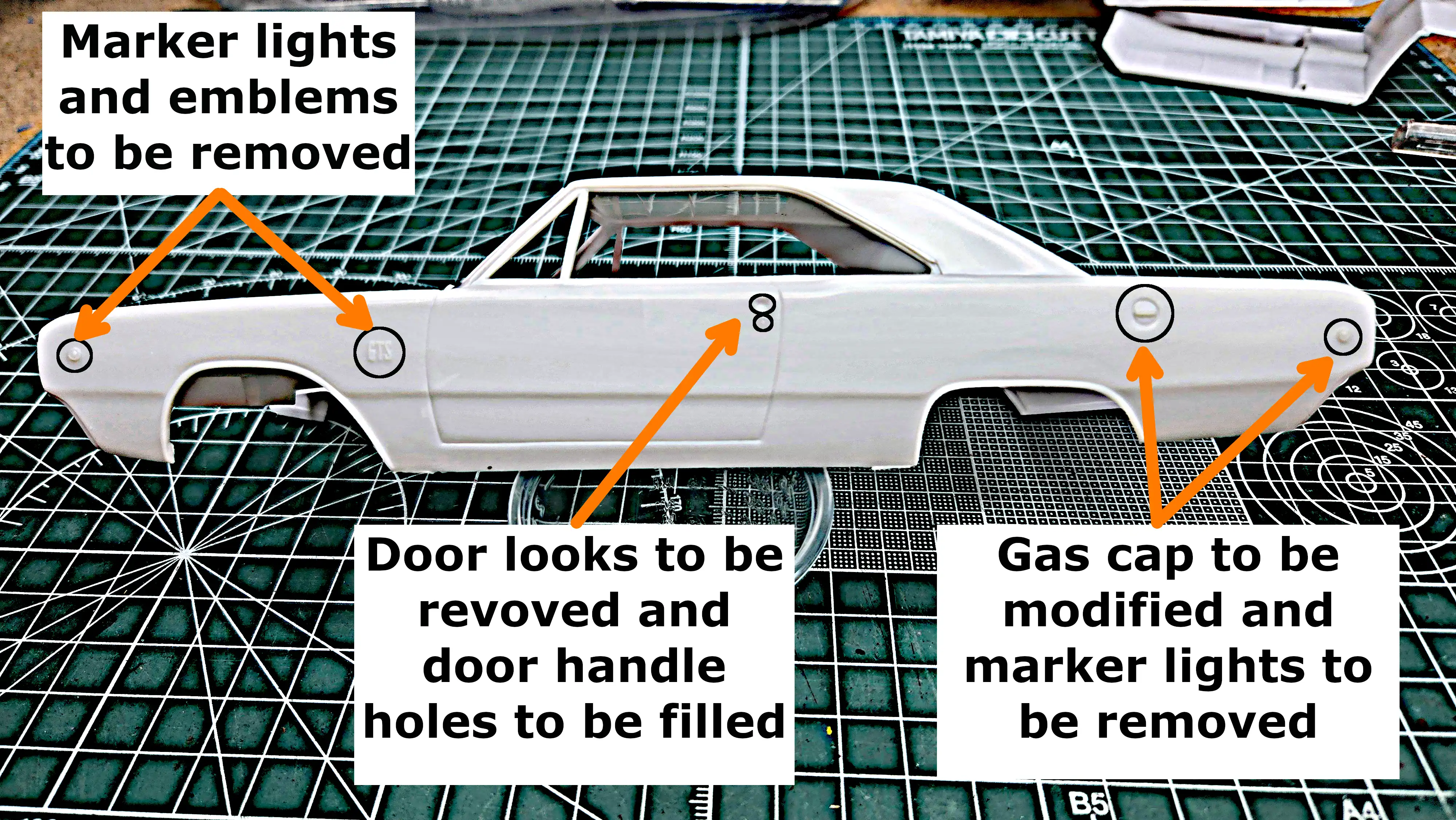 Body detail to be removed
 Right side of body with detail removed and filled
 I'll be removing the gas tank and spare tire well
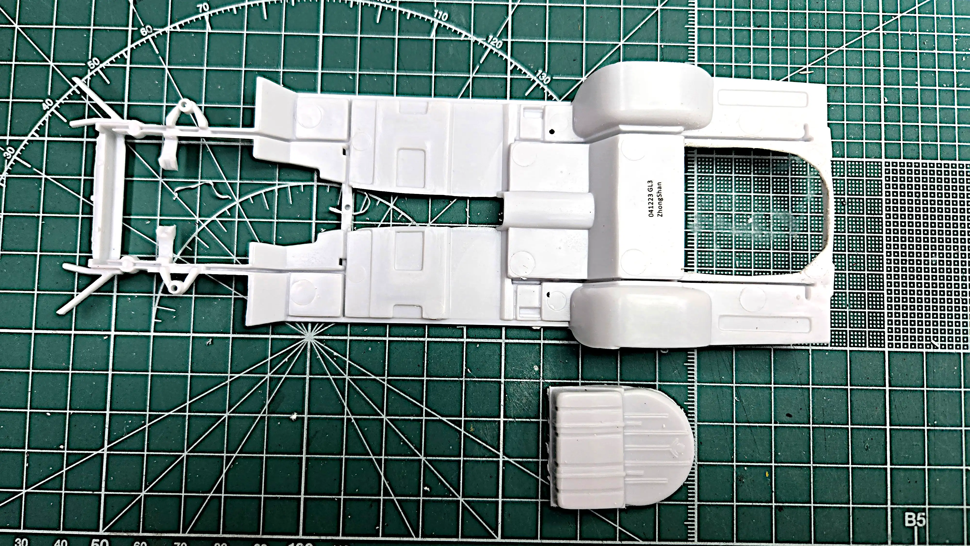 The gas tank and spare tire is cut
from the frame
The gas tank and spare tire is cut
from the frame
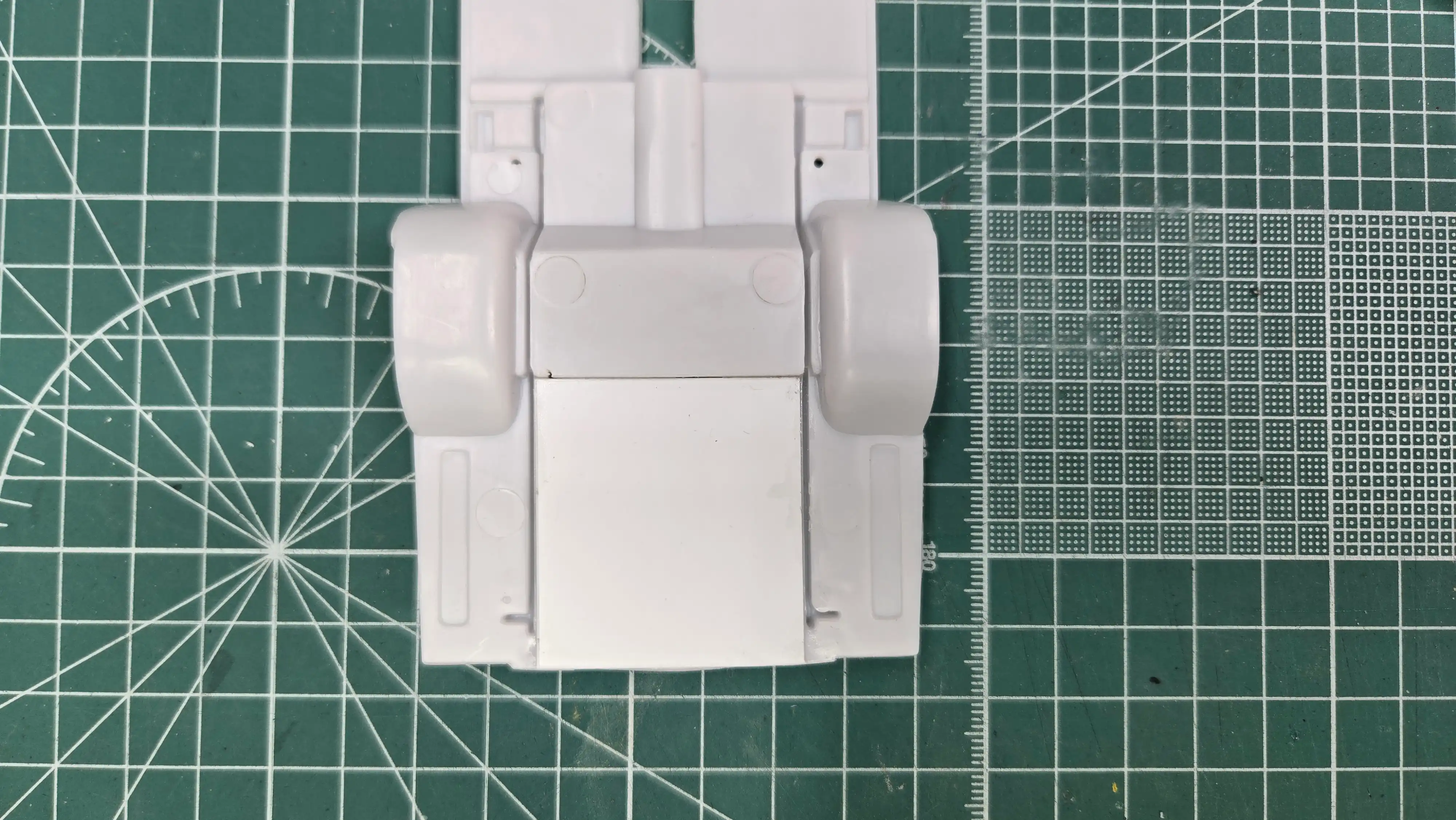 Trunk floor is closed
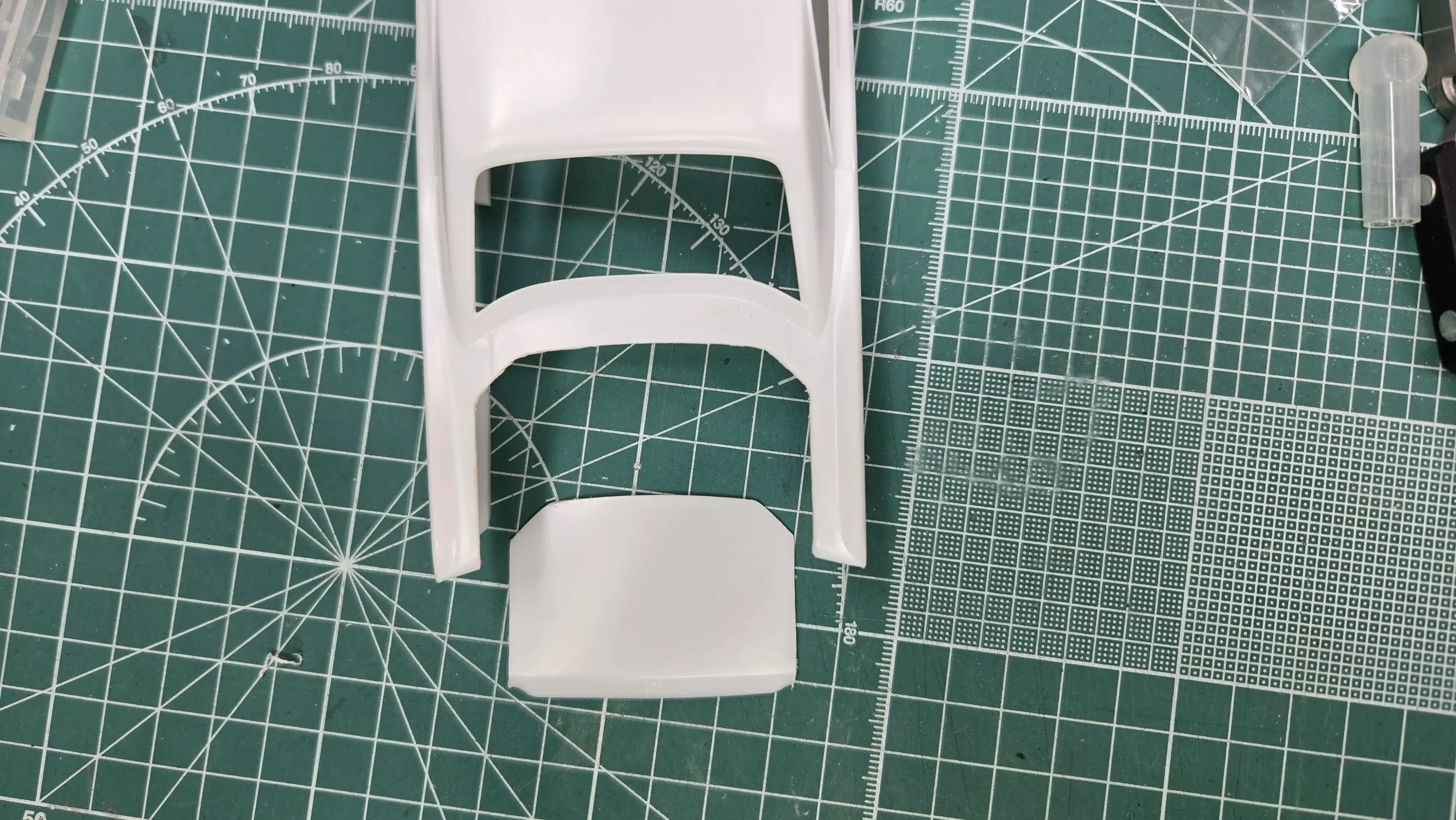 The trunk lid has been cut open
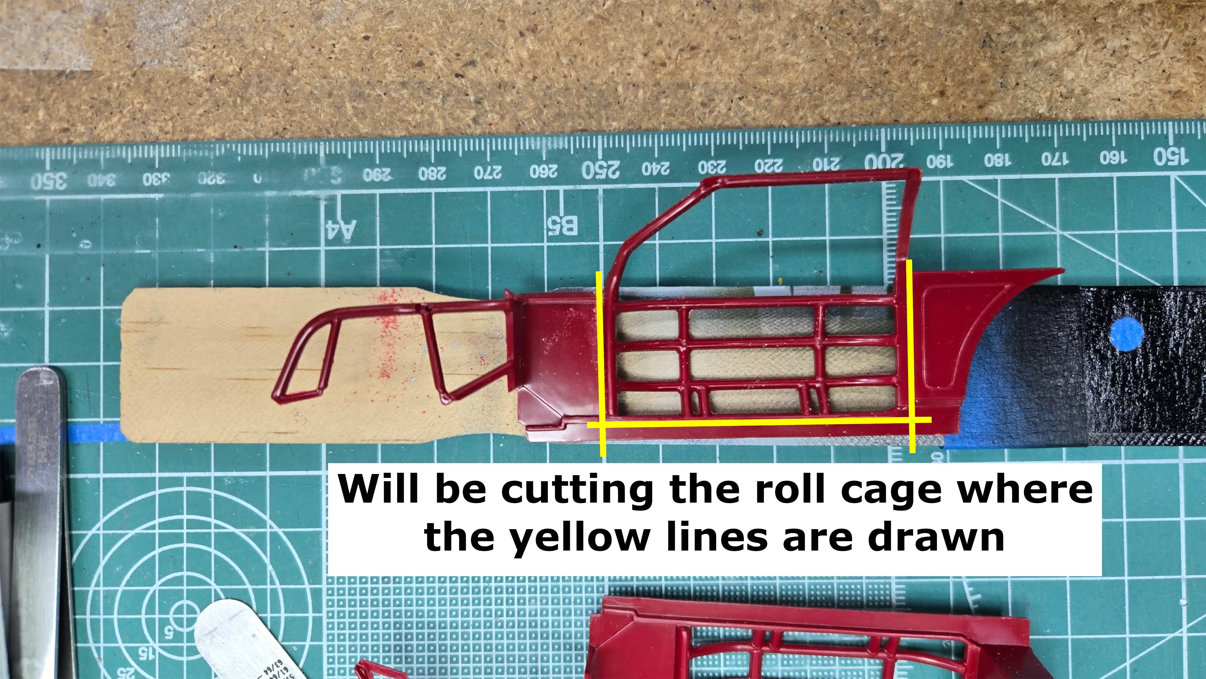 Location where roll cage will be cut
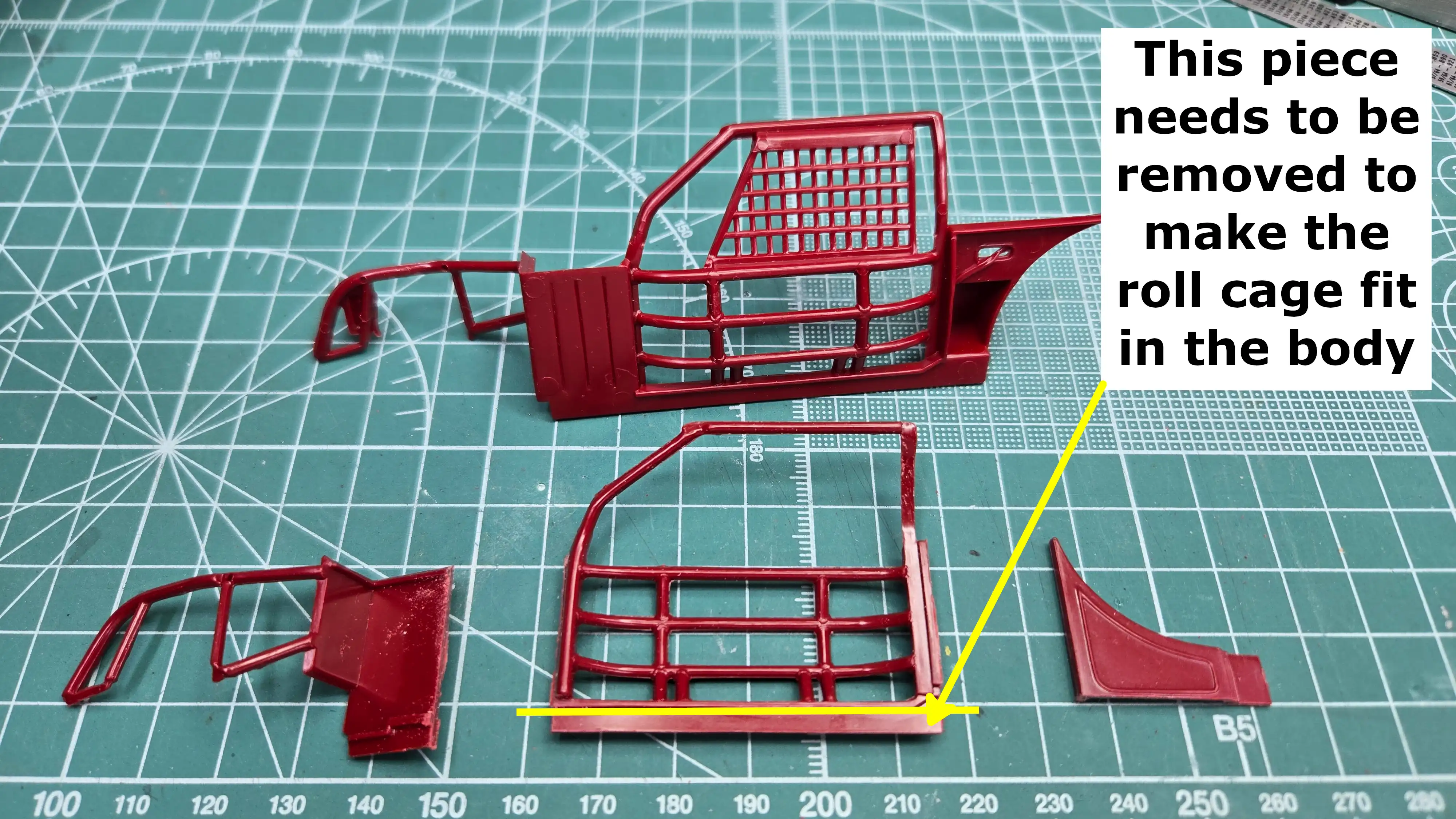 Bottom strip of roll cage must also be removed
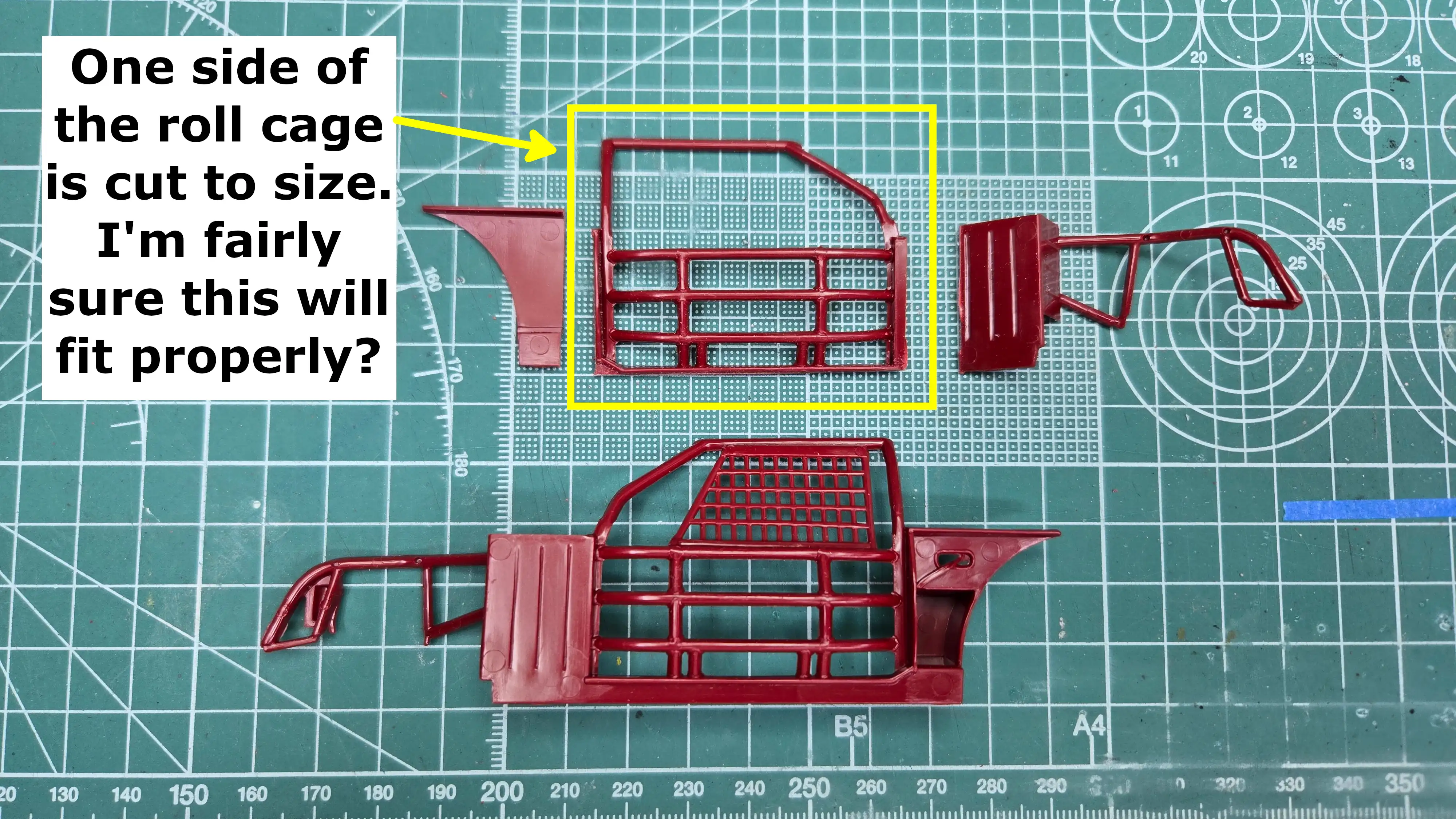 One side of the roll cage has been cut out
 Both side of the roll cage are cut to size
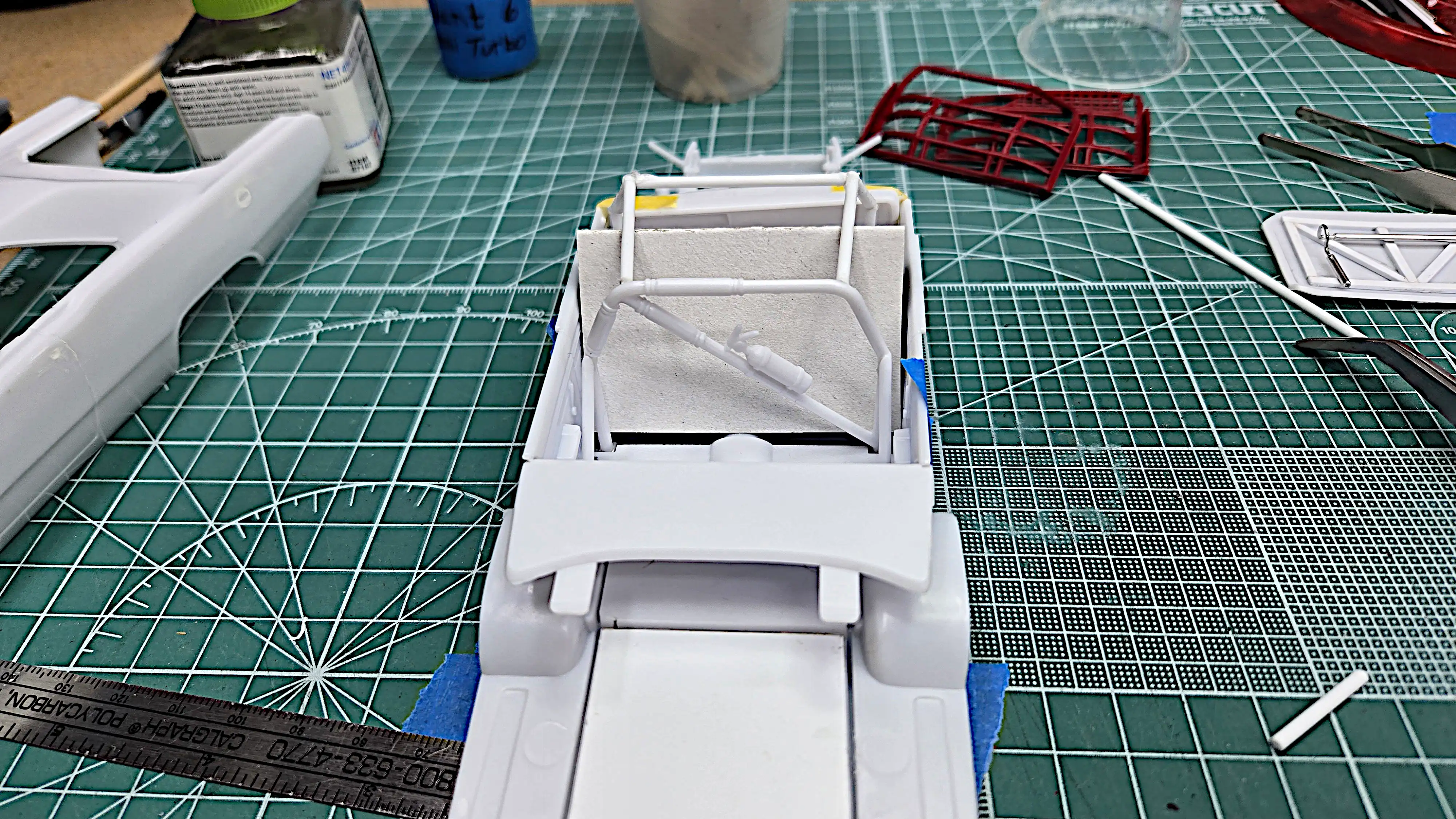 Back view of my scratch built roll cage with helper
 Right side view of my scratch built roll cage with helper
 Scratch built roll cage on floor pan, right side
 Scratch built roll cage on floor pan, front view
 Scratch built roll cage on floor pan, left side
 Scratch built roll cage on floor pan, back view
 Differential and rear leaf springs installed
 Left side of frame and roll cage shown the stance
 Left right of frame and roll cage shown the stance
 Front view of frame showing the stagger
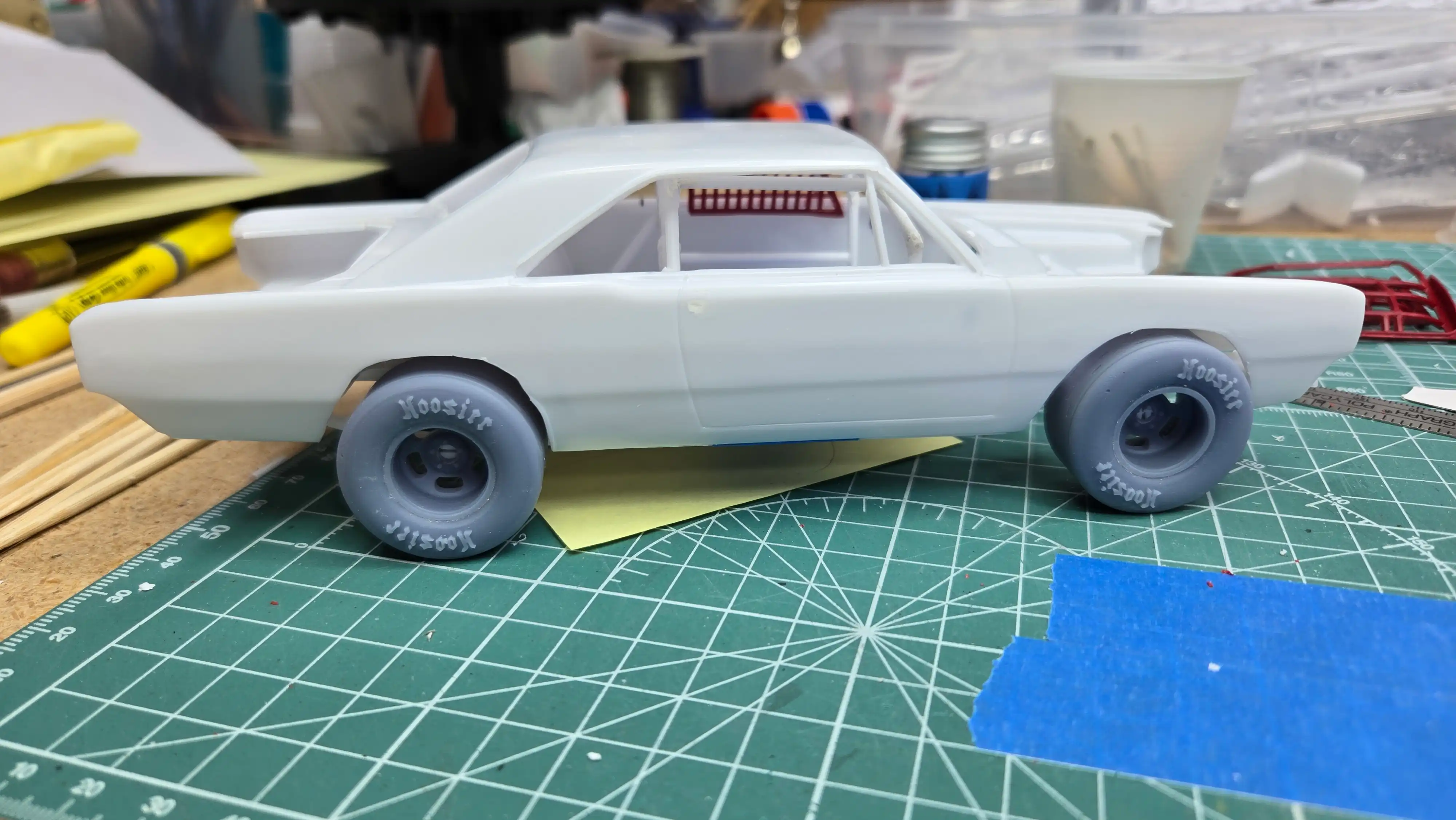
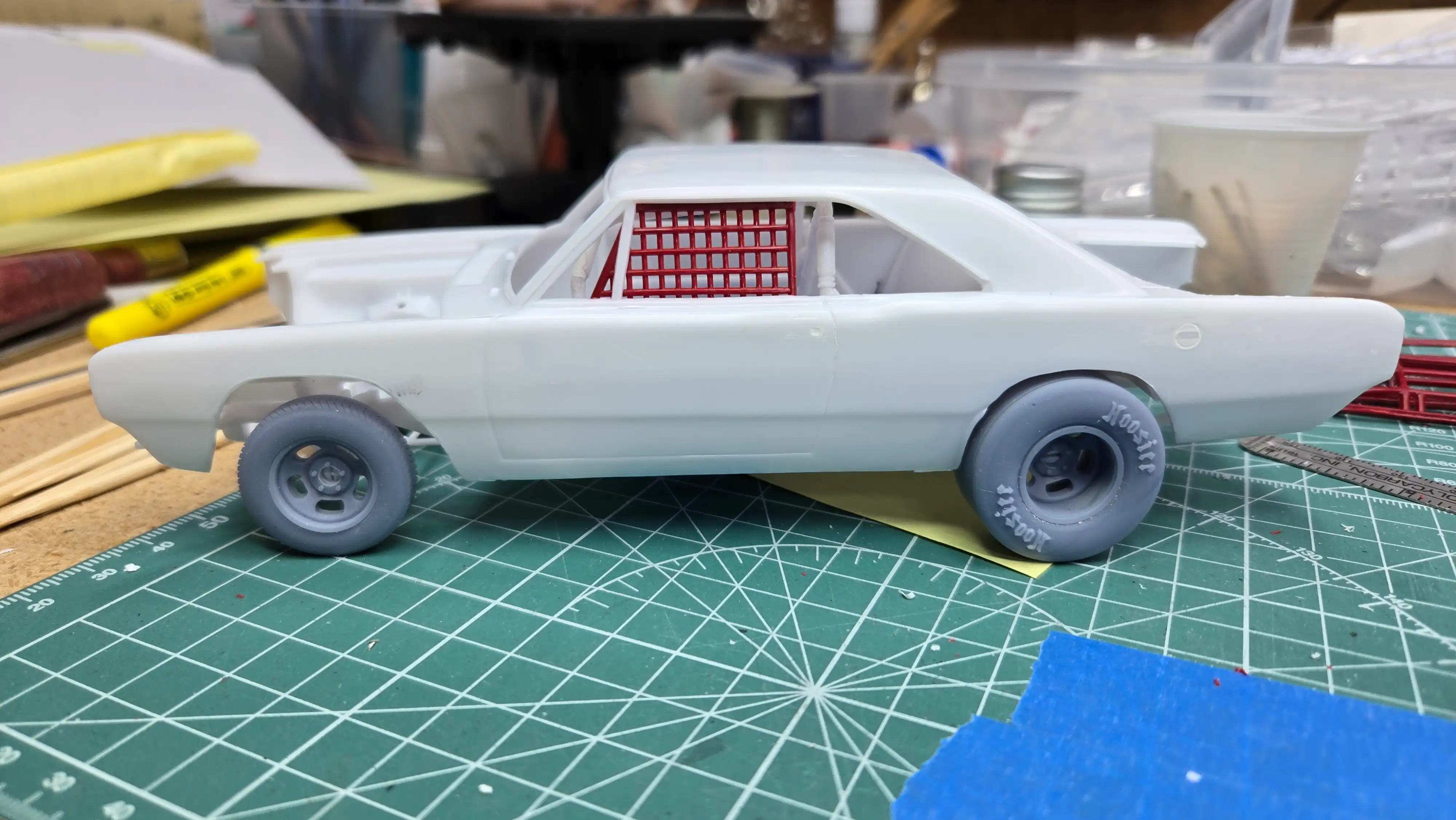 Left side with body dry fitted
 Right side with body dry fitted
 Rear view with body dry fitted
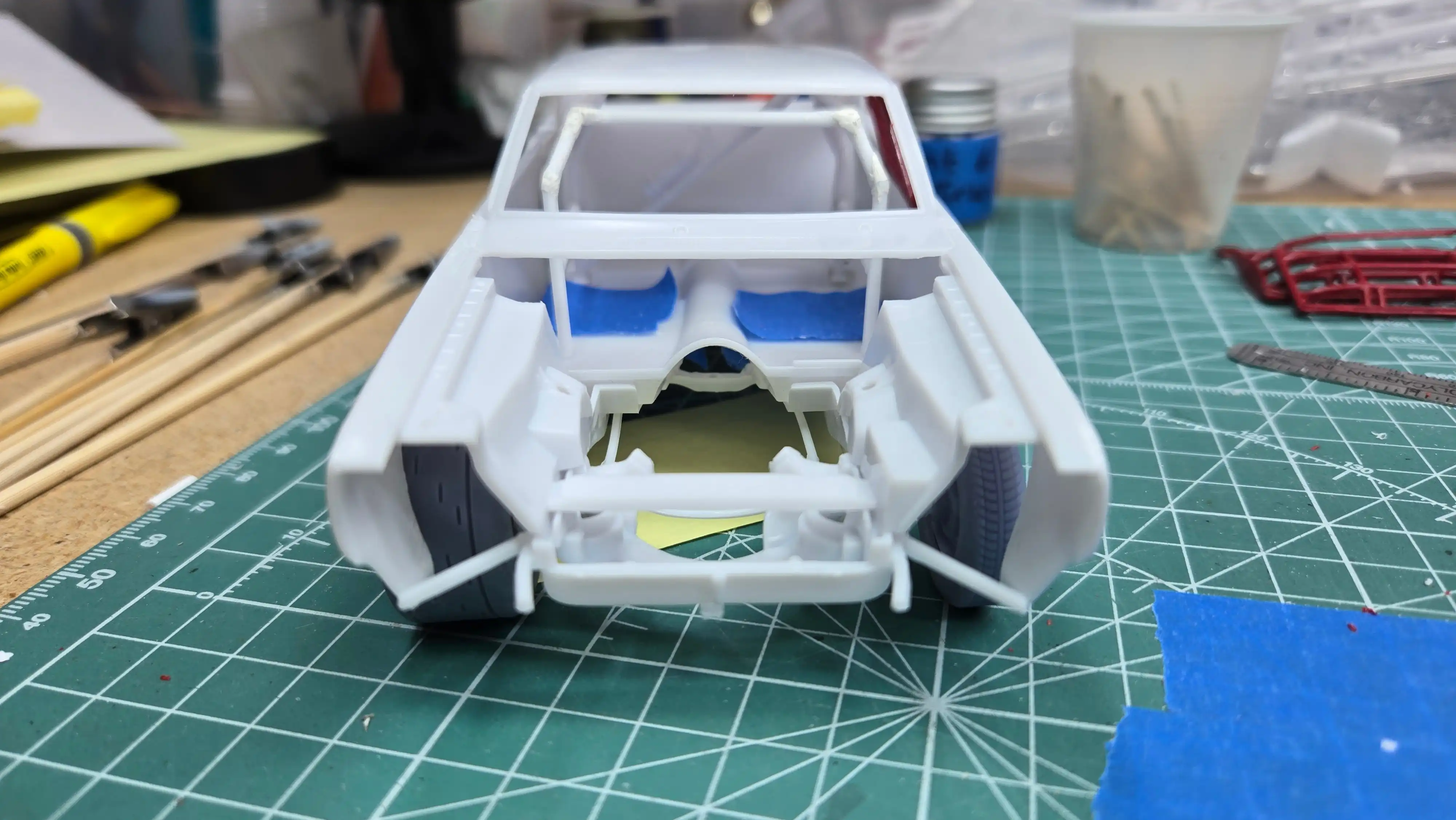 Front view with body dry fitted
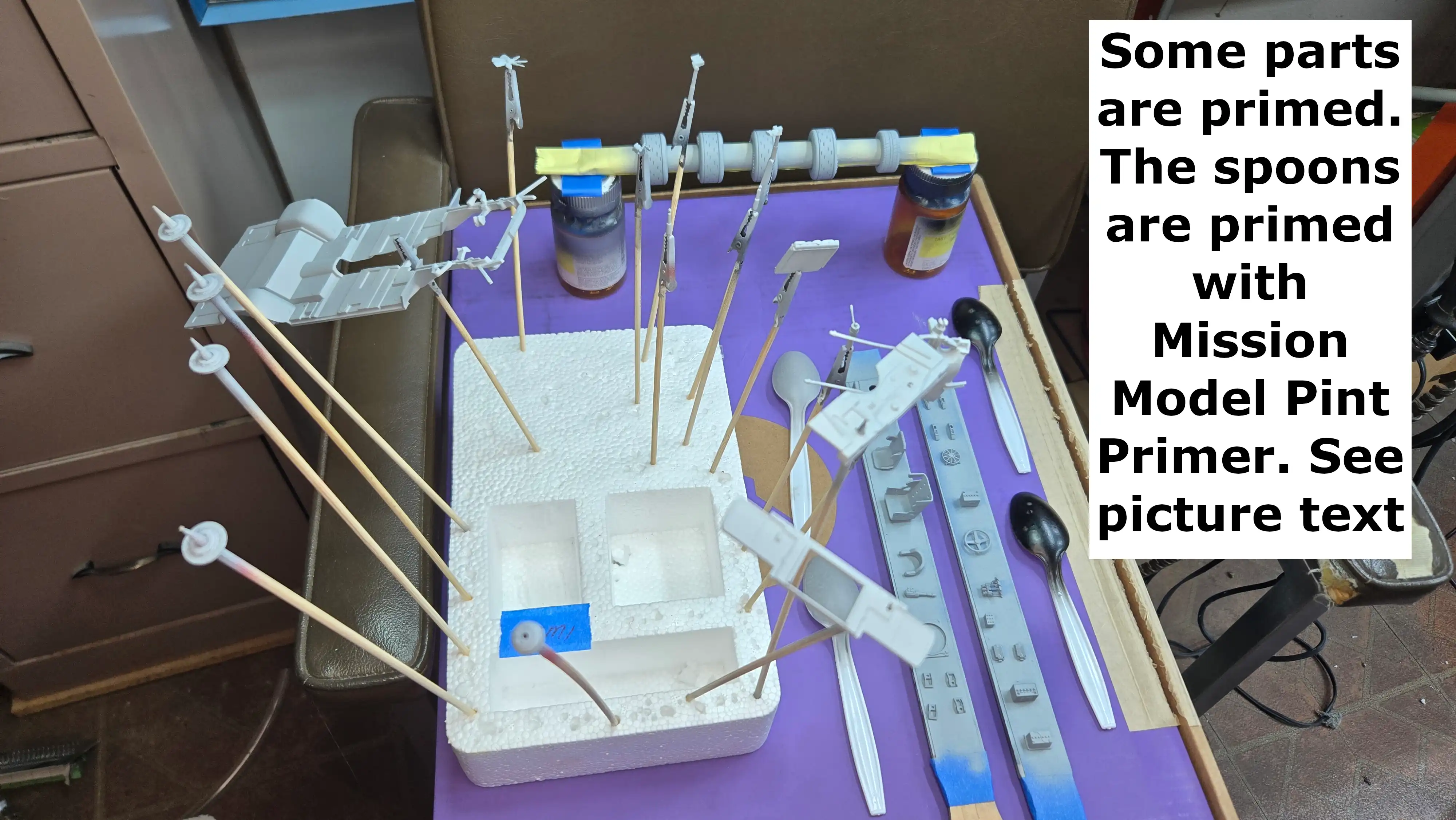 Some parts have been primed. See Photo Text
about the spoons in the photo
Some parts have been primed. See Photo Text
about the spoons in the photo
 All parts are now primed. See photo text.
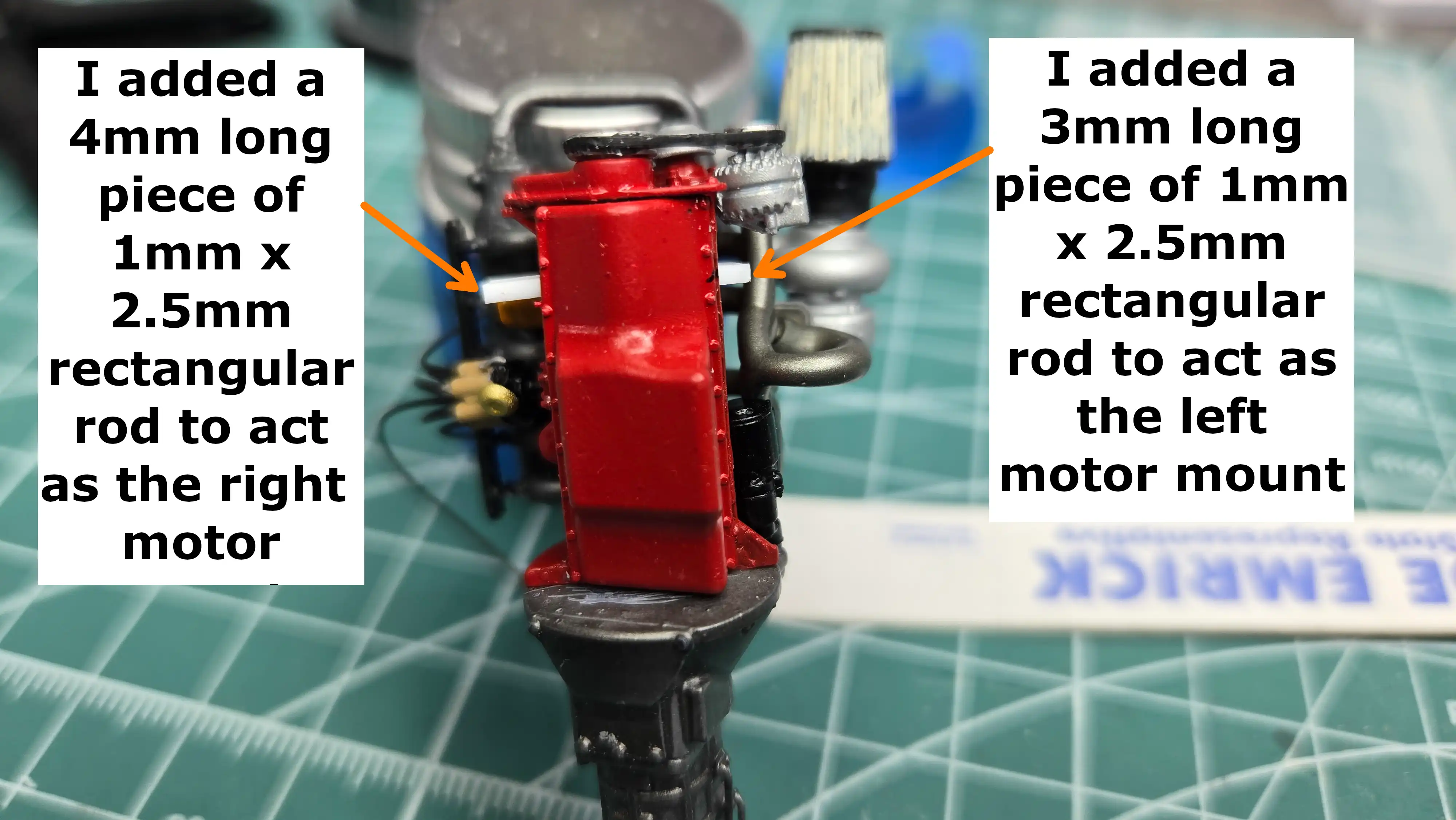 Slant 6 Hemi Turbo motor mounts
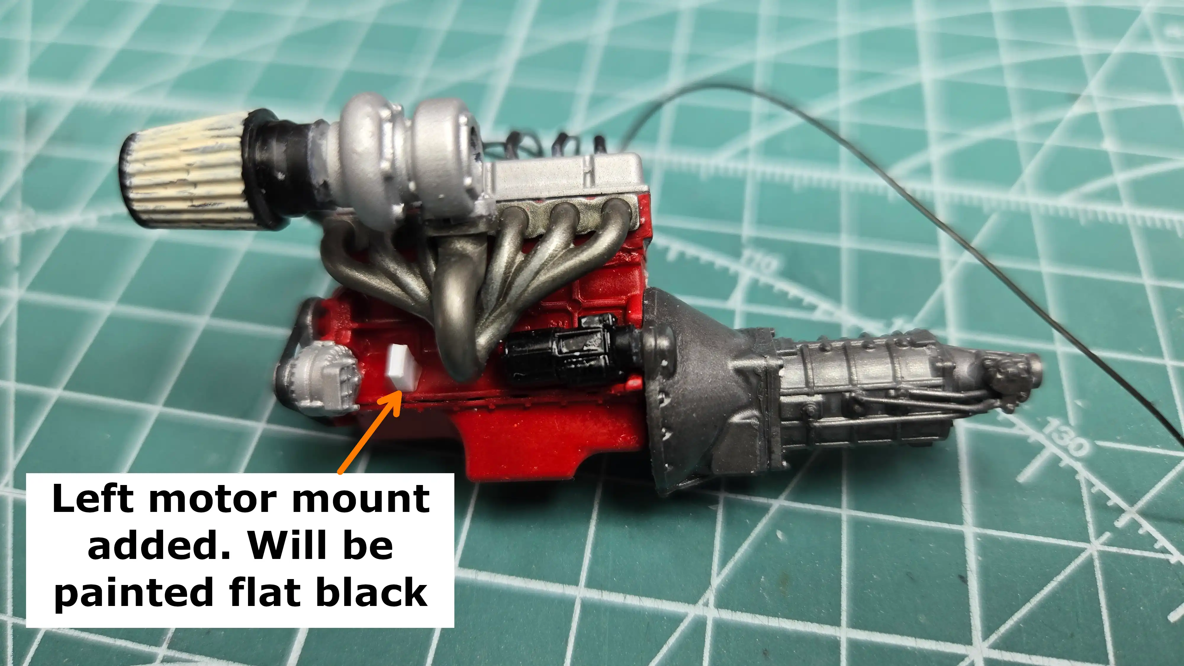 Slant 6 Hemi Turbo motor mounts - Left Side
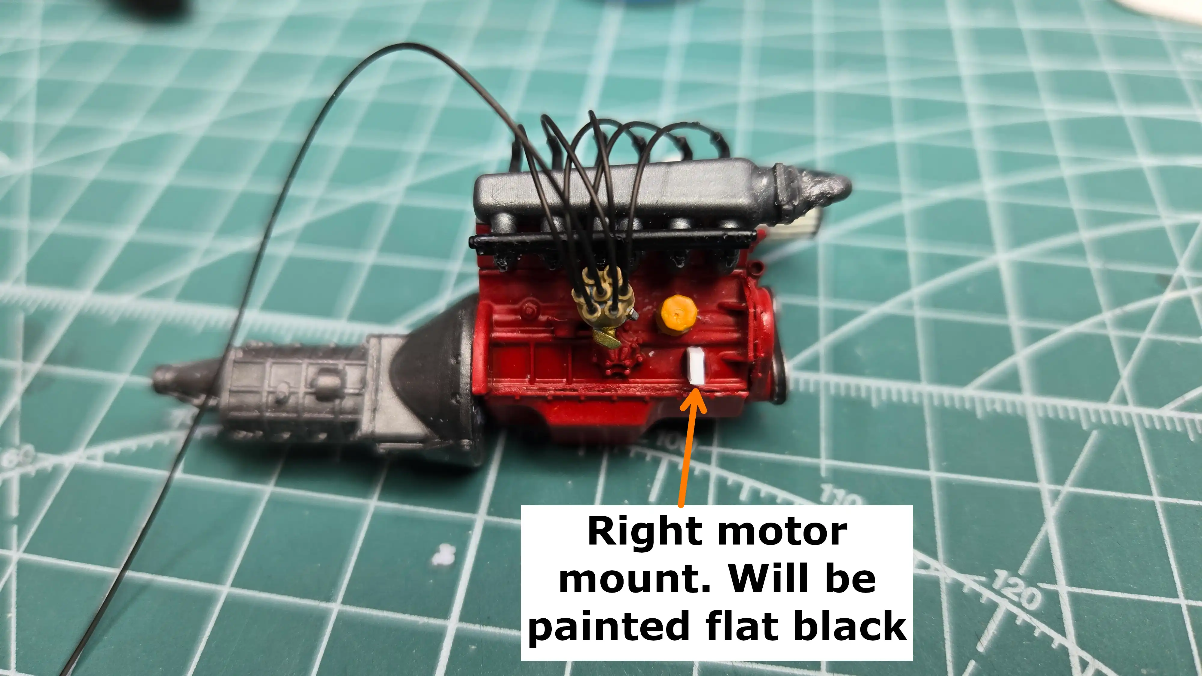 Slant 6 Hemi Turbo motor mounts - Right Side
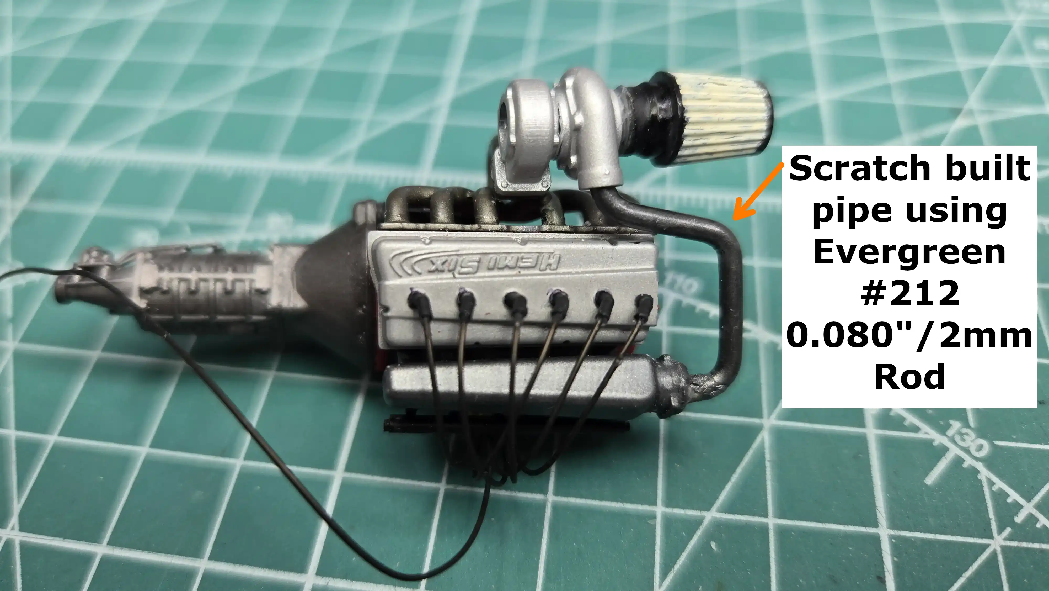 Engine turbo piping
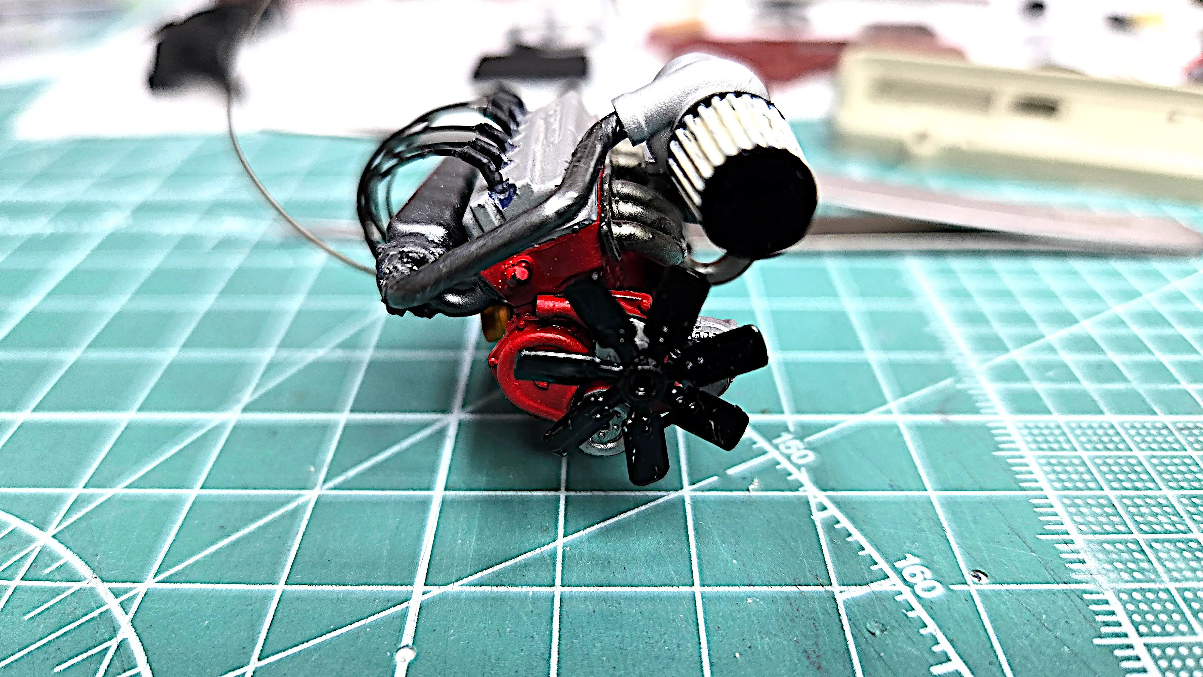 Front view of slant 6 HEMI with fan installed
 Most, if not all, parts have been painted
 Interior door panels
 Dashboard is painted and modified
 Drive shaft had to be lengthened
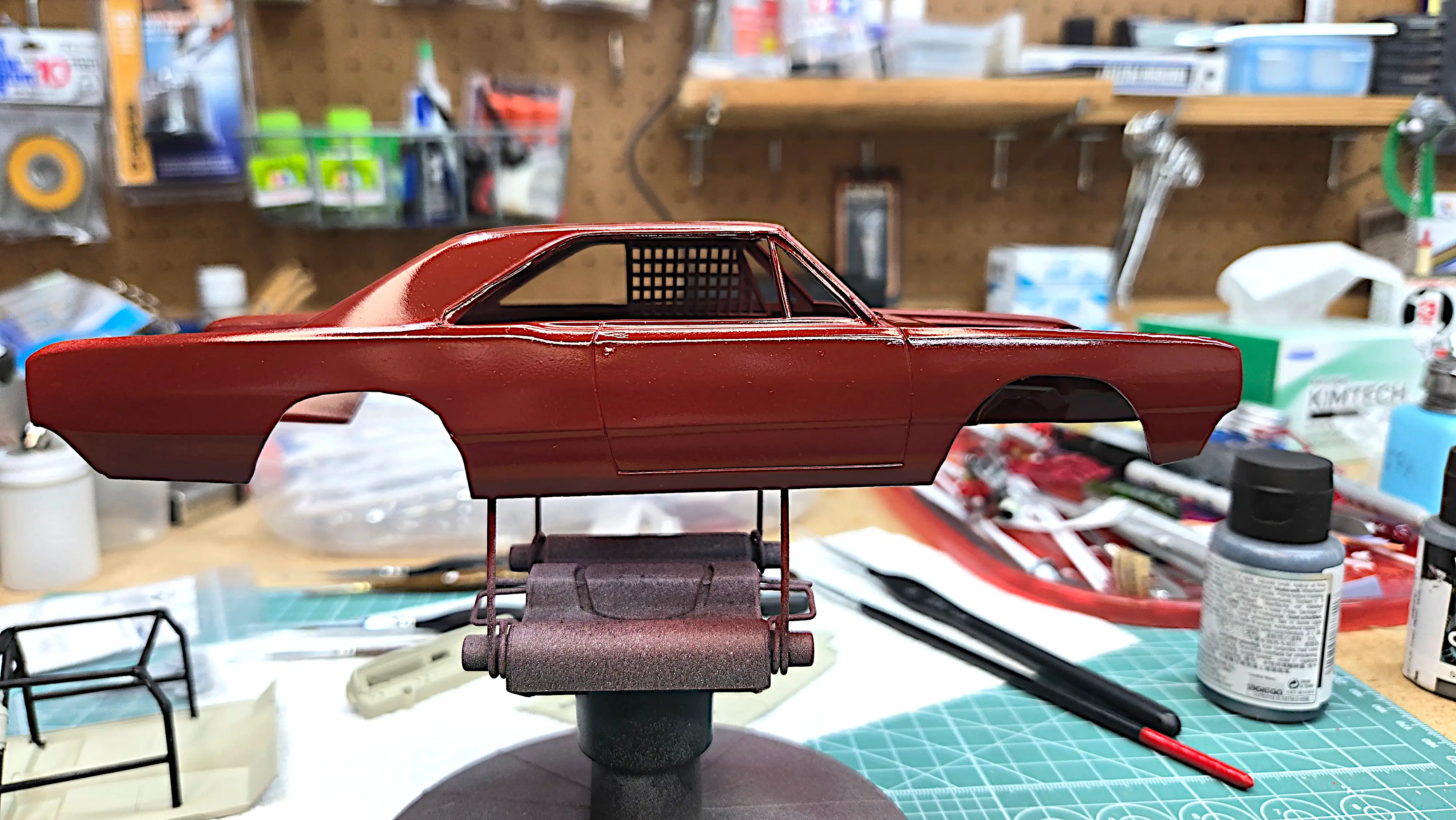 Body is painted burgundy
 Tires and wheels
 Racing seat with lap belts installed
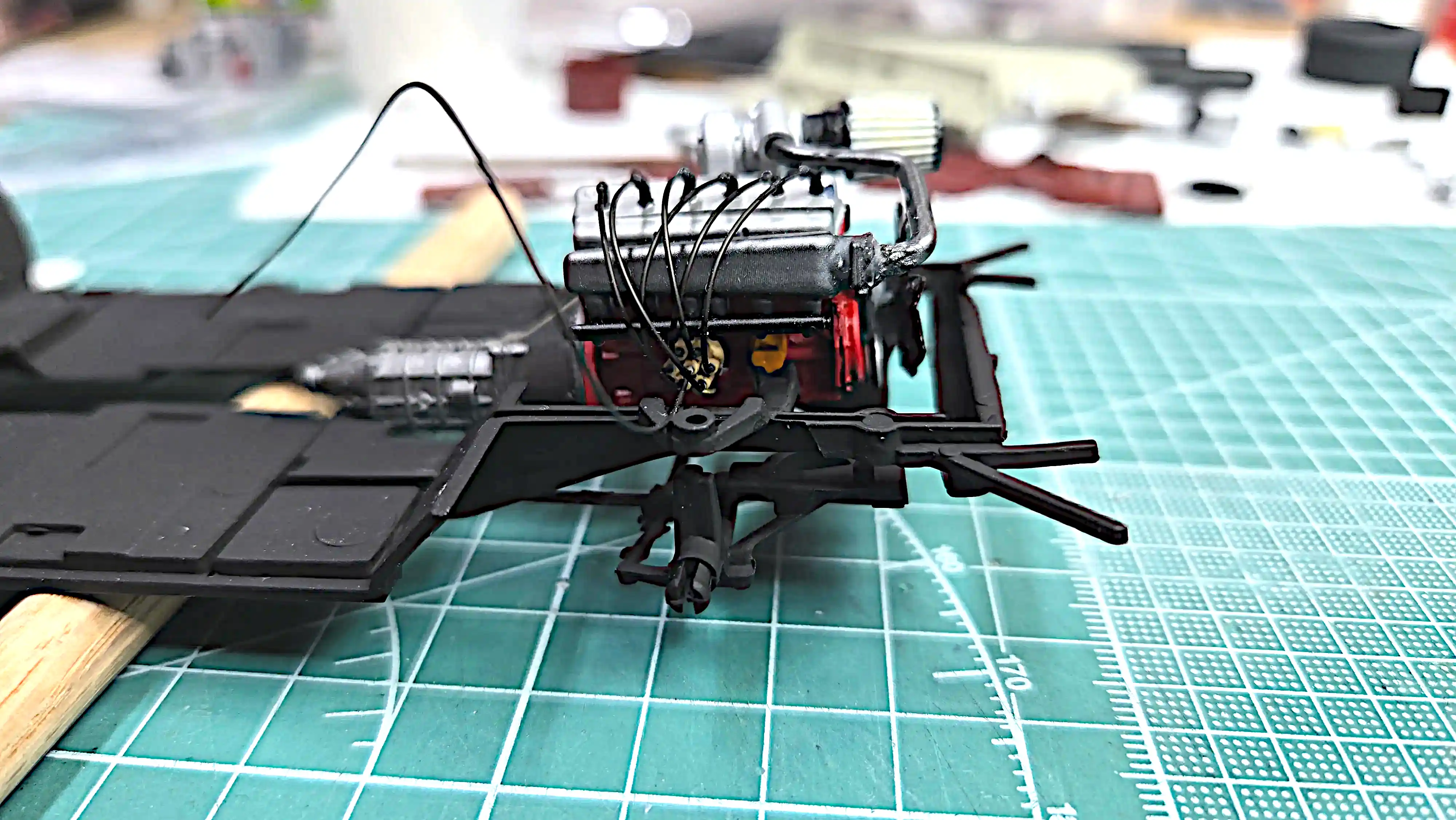 Slant 6 HEMI Turbo dry fitted
 Windshield screen
 All safety belts installed
 Interior floor pan, left side
 Interior floor pan, right side
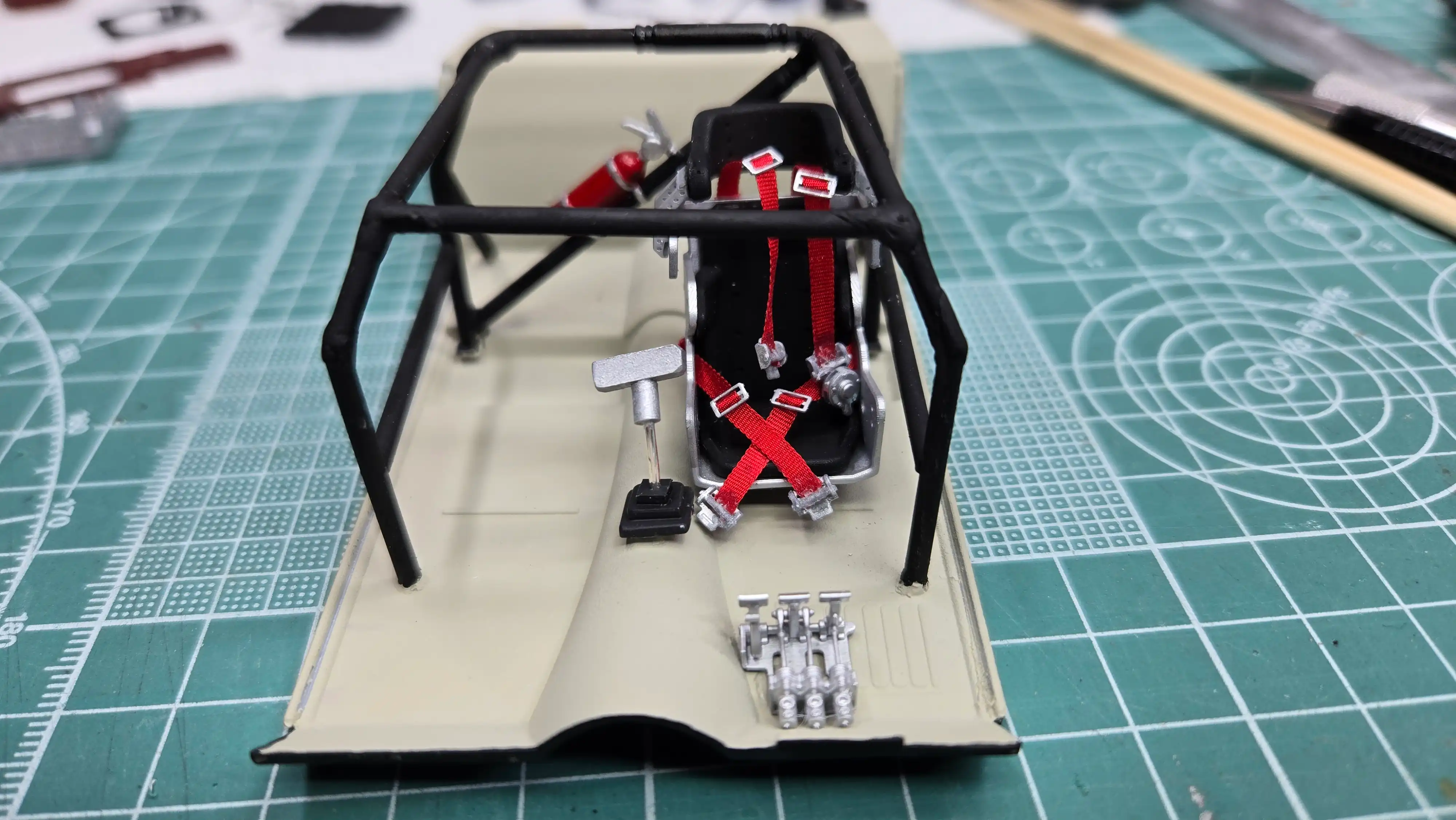 Interior floor pan, front view
 Slant 6 HEMI Turbo and drive shaft are mounted on the frame
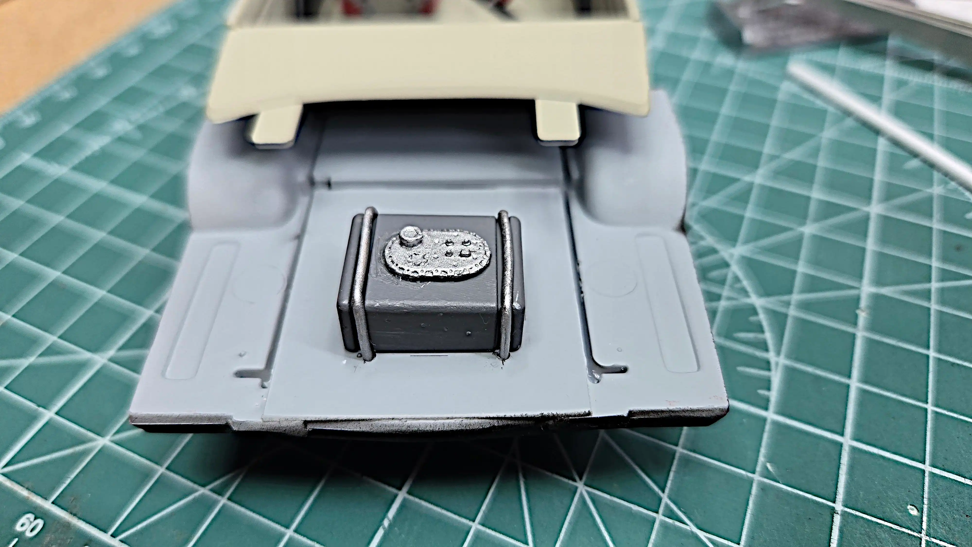 Fuel Cell hold-down straps are added
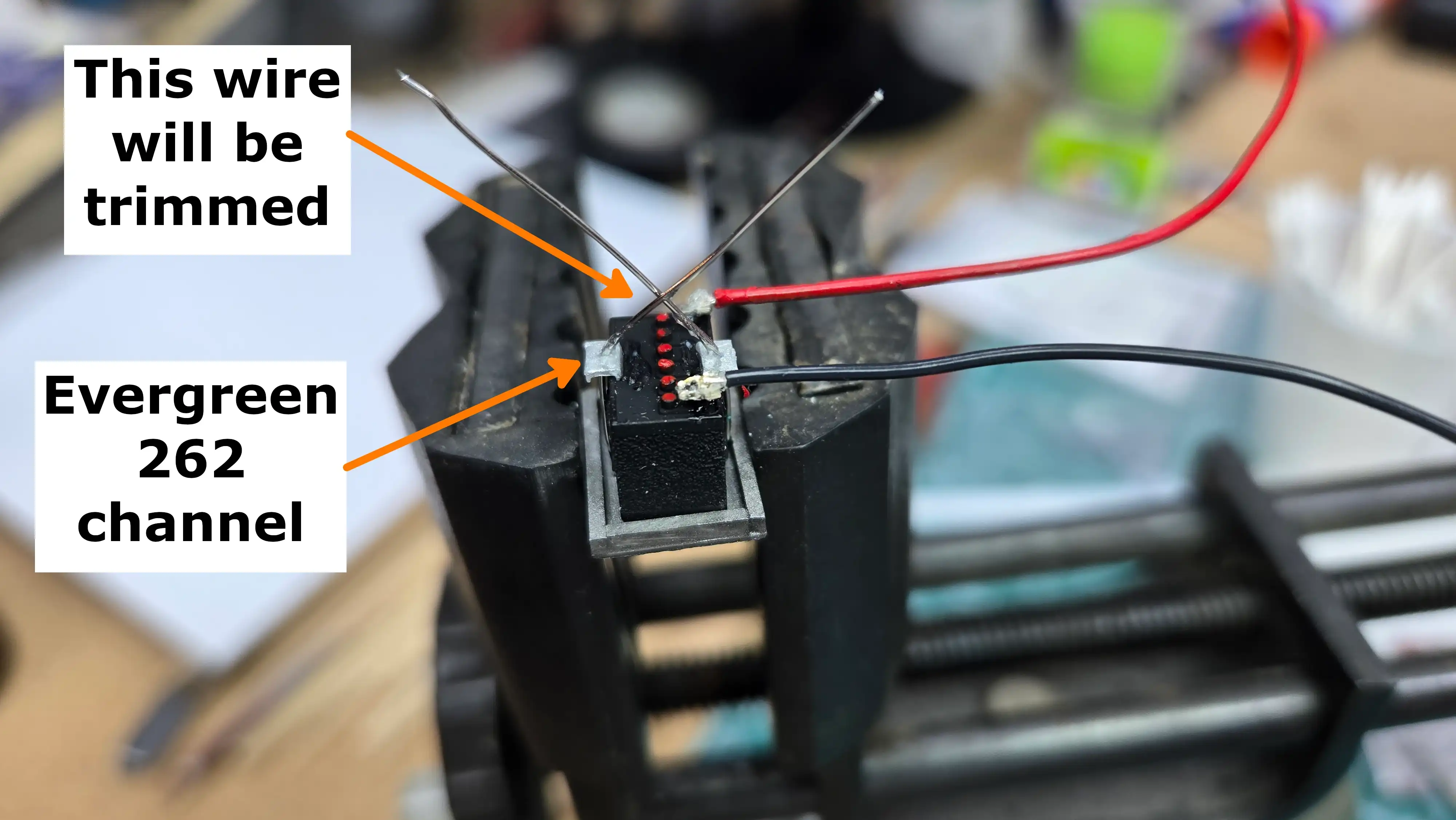 Battery hold-down and wires added
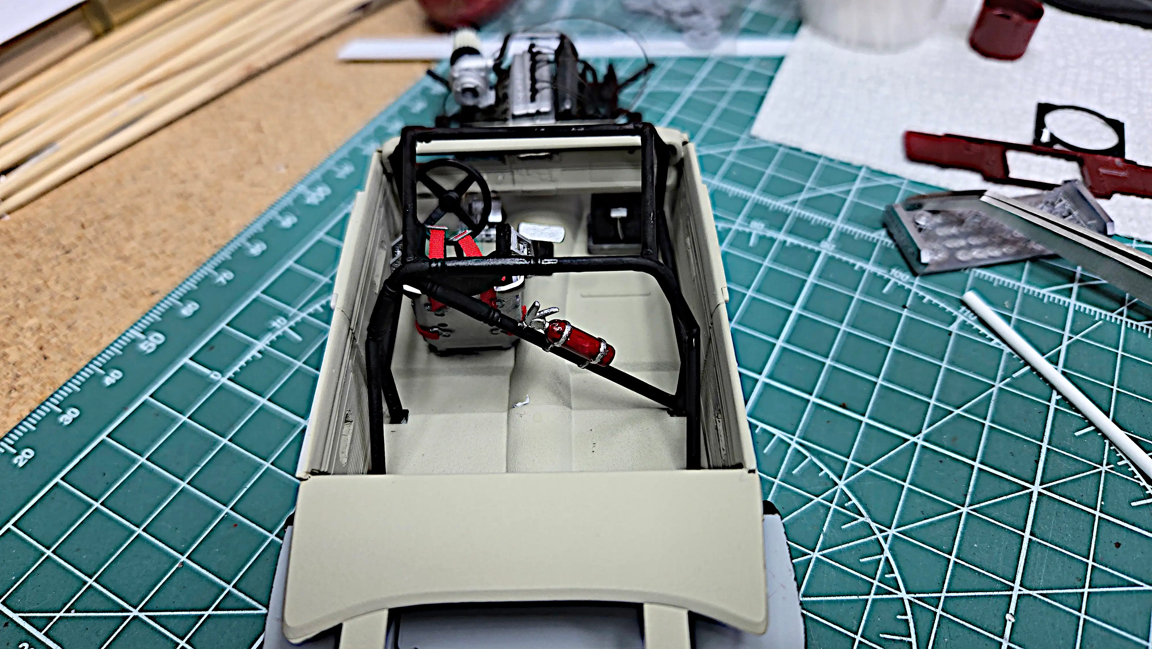 Battery installed under the dashboard
 Battery installed under the dashboard - closer view
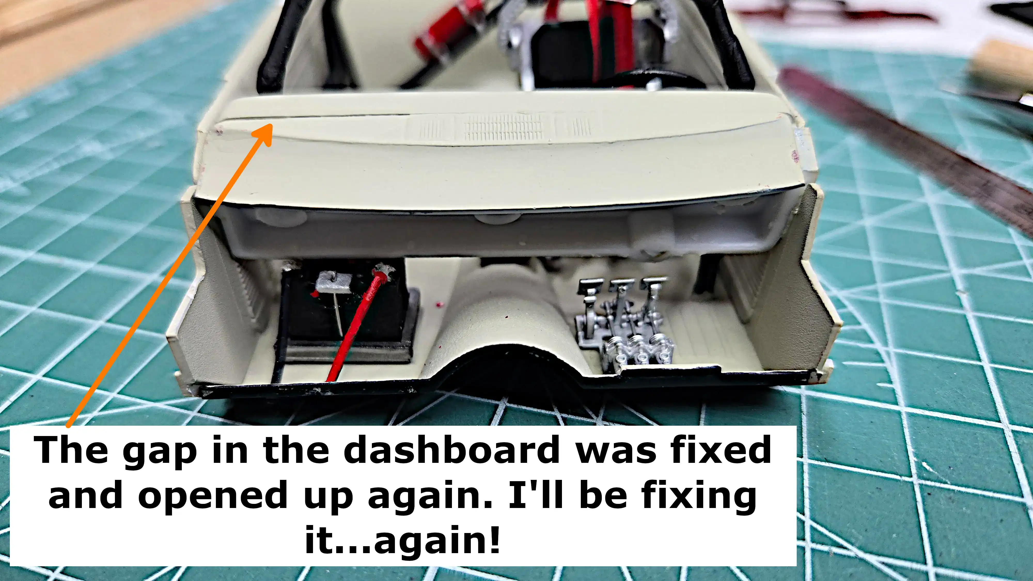 Front view of battery mounted under the dashboard
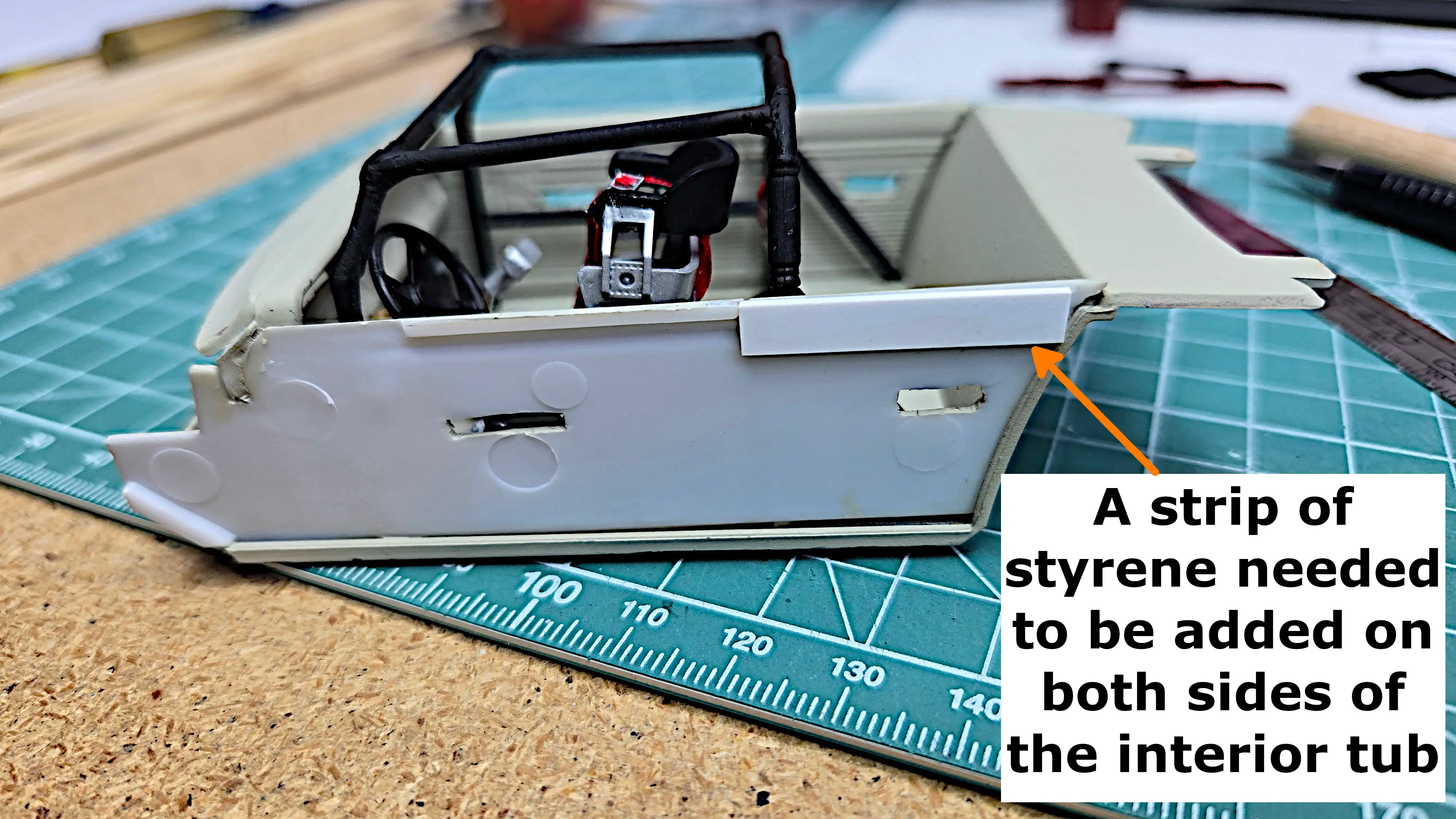 Styrene strip added to interior tub
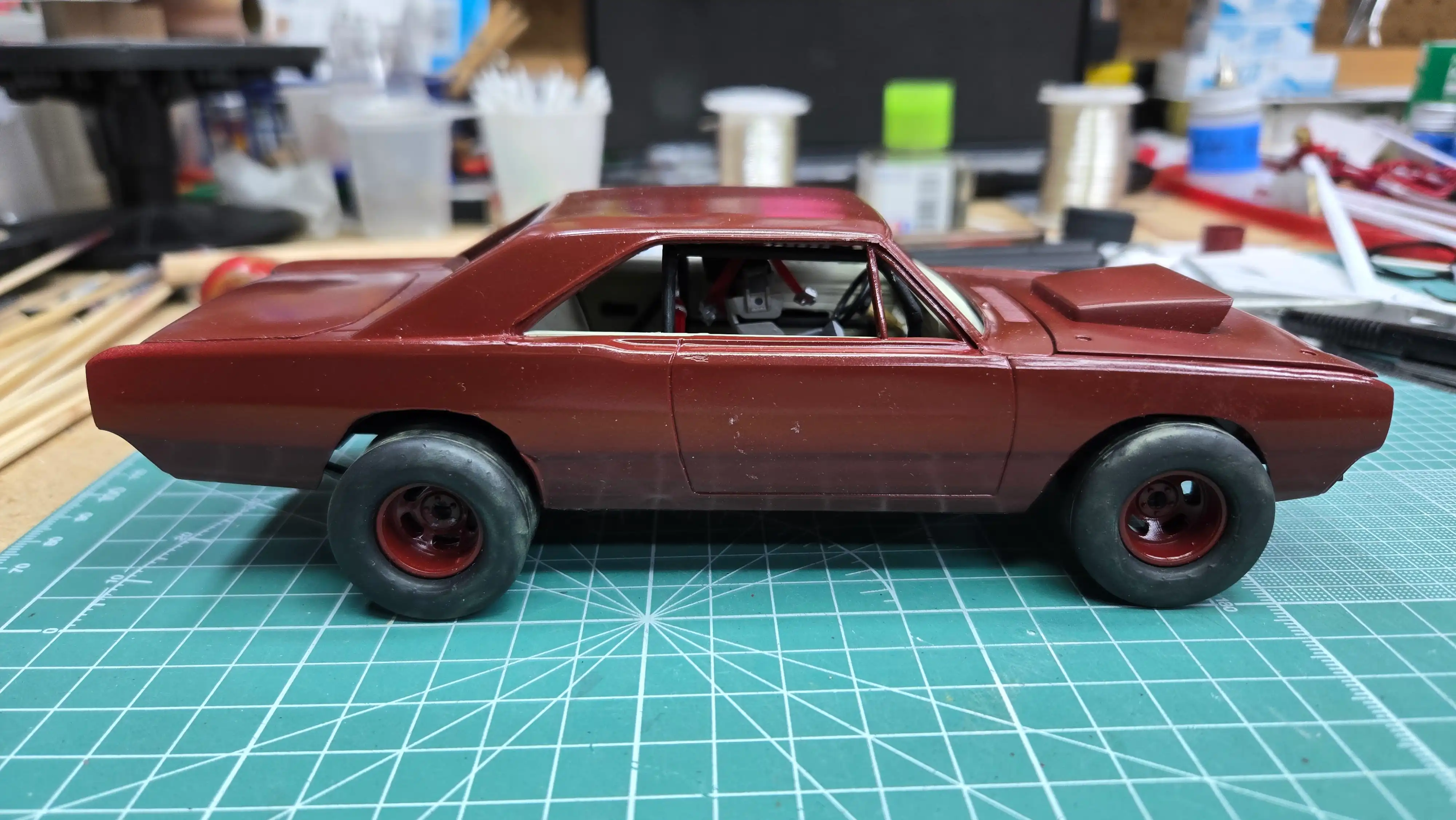 Mostly assembled, almost finished
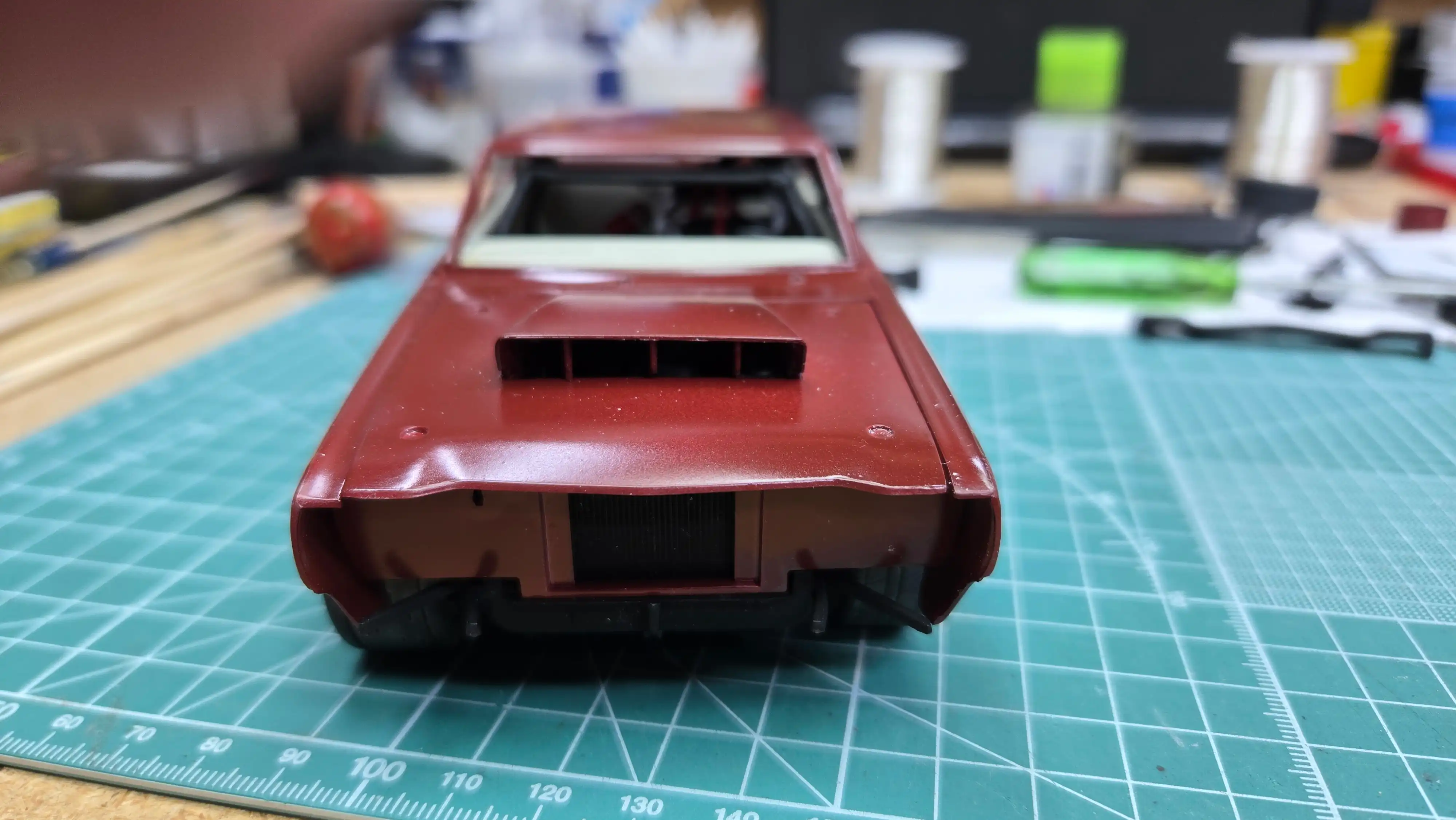 Front view with hood in place, but no bumper or grill
 Engine compartment is almost finished
 Trunk hinges are installed
 Screen windshield and grill installed
 Engine compartment is finished
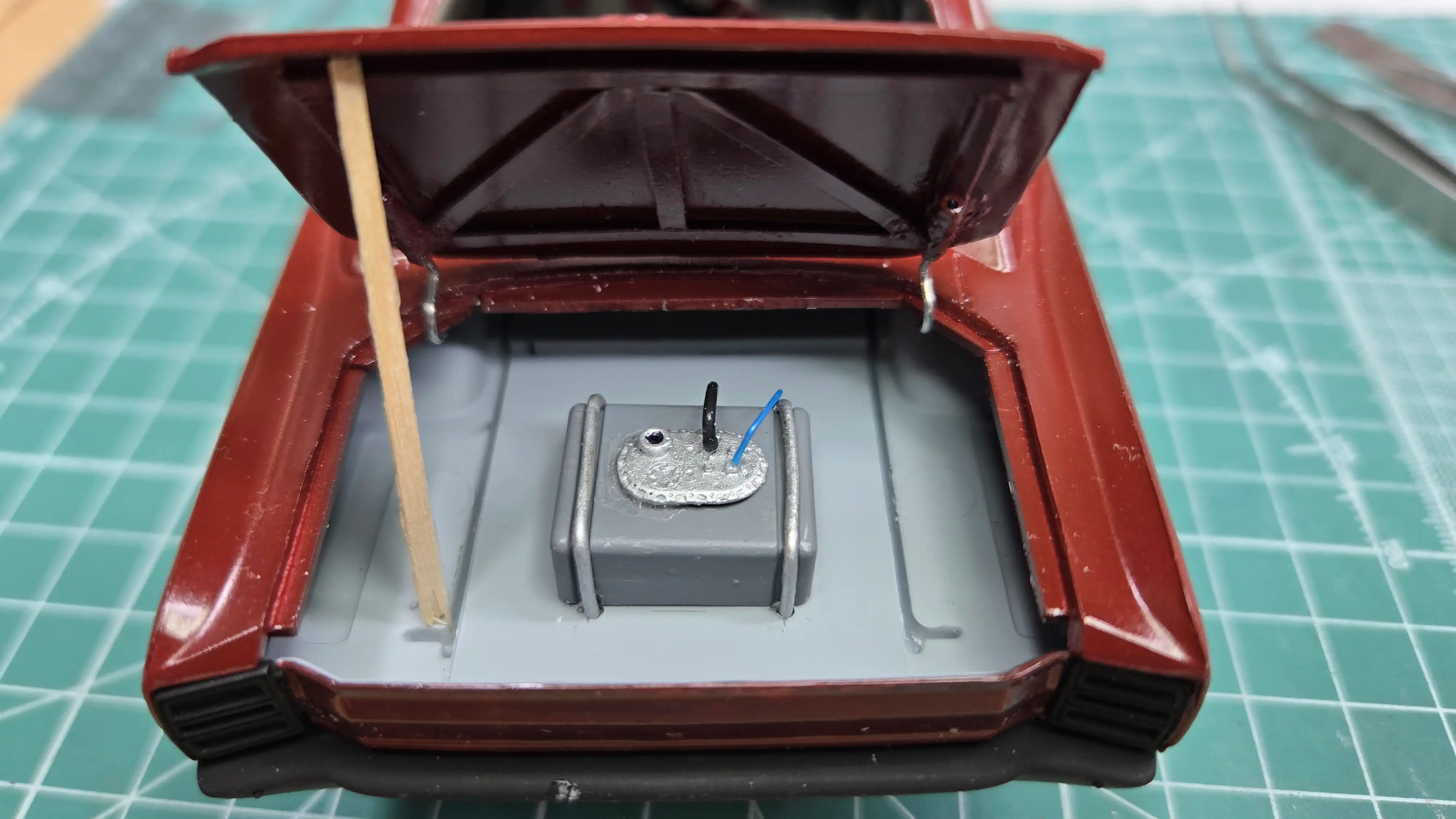 Fuel lines added to the fuel cell
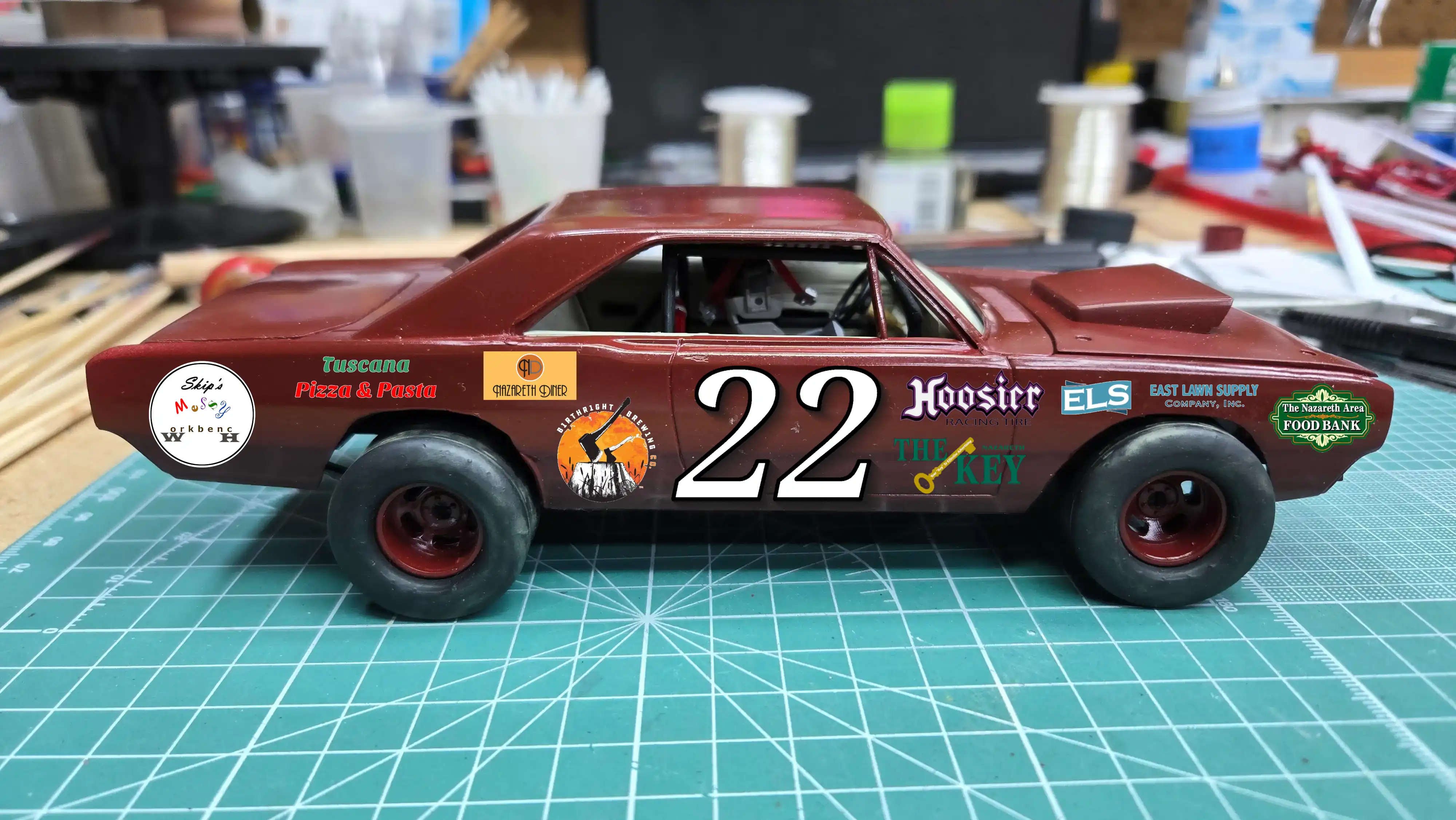 Mock up of how the decals should look
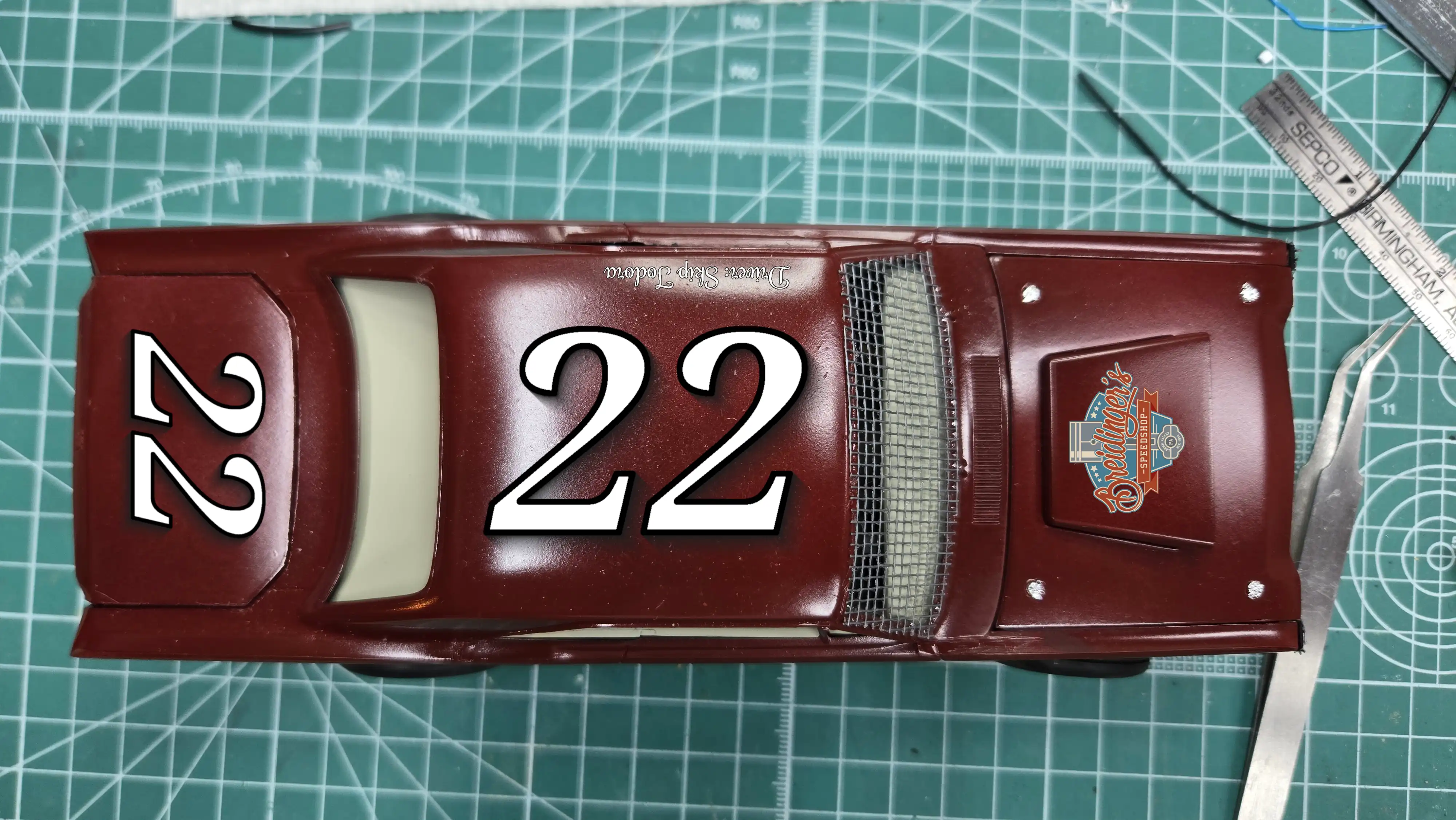 Mock up of how the decals should look
 The decals I'll be using

