My next build was going to be a 1941 Chevy Pickup. While I was
doing research for the build I discovered a lot of very interesting
information and history about this particular year pickup. I also
learned that 1941 was the last time America build any civilian
vehicles until after World War II and the "big 3", Ford, GM and
Chrysler had converted their factories over to war time production
building military equipment. In fact, Ford built a brand new plant
to produce the B-24 Liberator. This, and the fact that I have a
'41 Plymouth Coup and a B-24 Liberator in my stash, I decided to
start a build series that I'm calling...
AMERICA GOES TO WAR
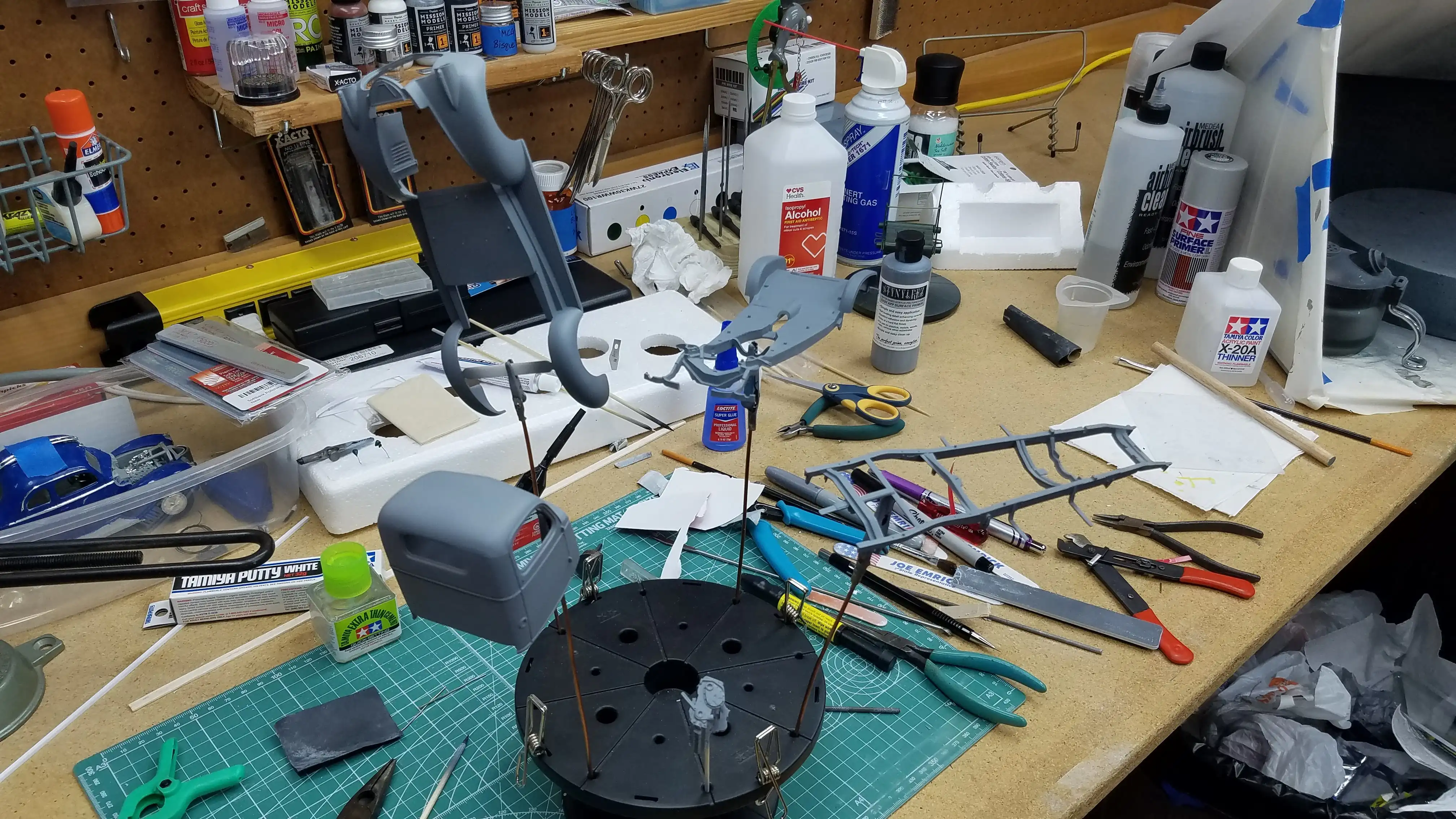
I got so excited about this I decided to build all three at
the same time:
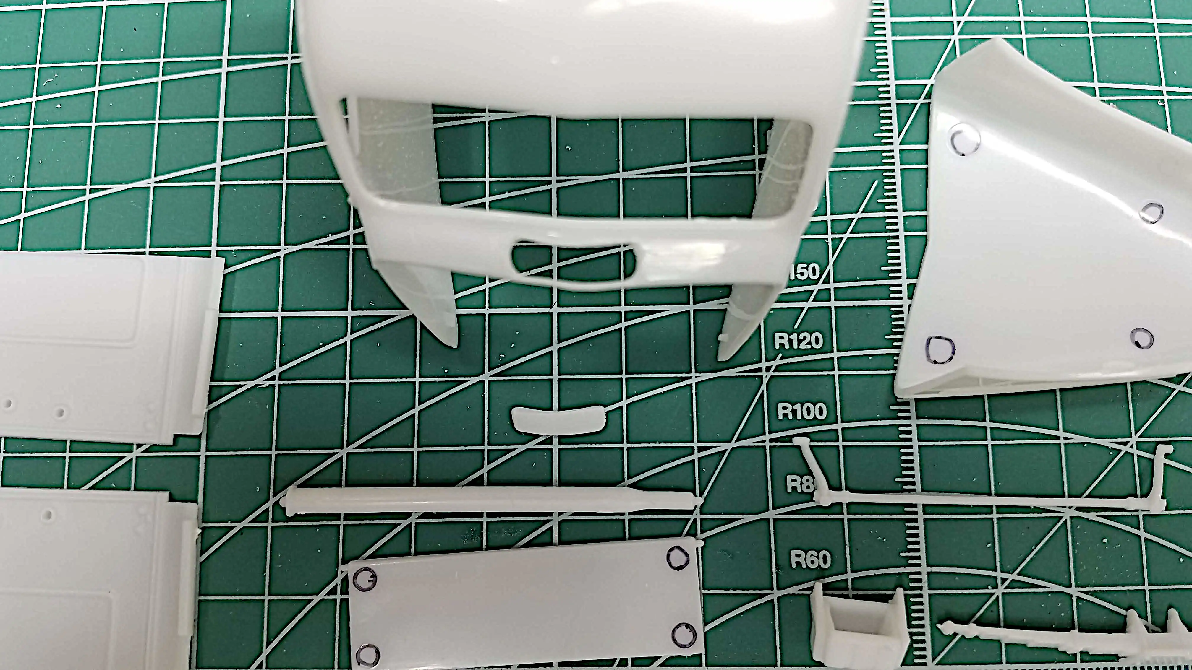
My plan is to cut the cowl vent open and I
started doing that in this photo. Once the
cowl vent is open, there is a modification
that has to be made under the cowl as shown in
an upcoming photo.
Under the cowl vent there is an alignment tab to indicate where
the firewall sets. This alignment tab will be removed when the
cowl vent is opened. I mocked-up the firewall, heater unit,
dashboard and floorboard and installed the assembly in the cab
to check for clearance for the new alignment tabs. I drew a
line showing where the firewall will be setting and then cut
two new alignment tabs using Evergreen #125 0.10 x 0.10 square
rod and glued them in place.
The engine, when the two halves are put together,
shows the valve rocker arms in a-bit of detail.
I'm considering detailing the rocker arms and
making the valve cover removable to showcase them.
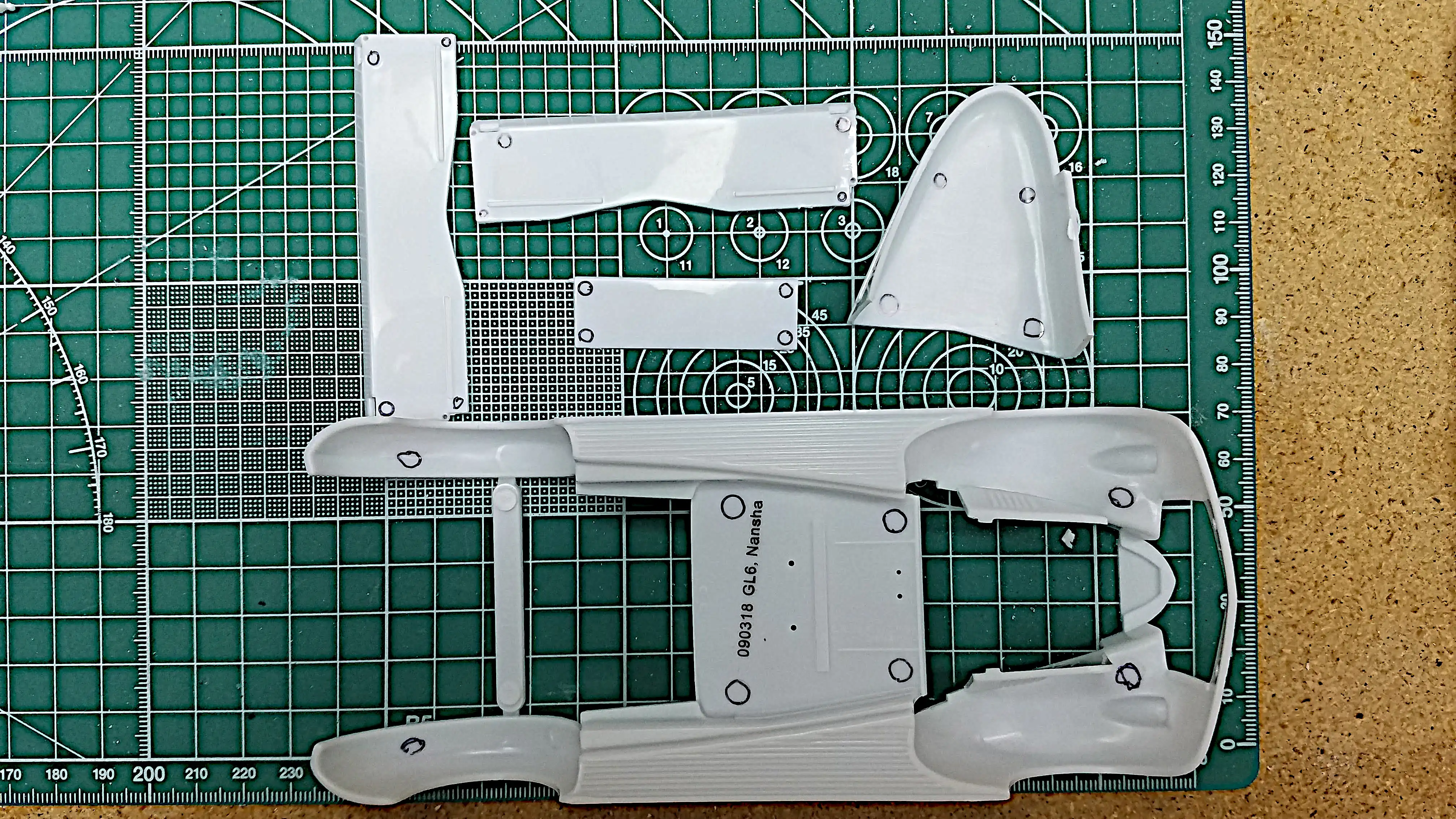
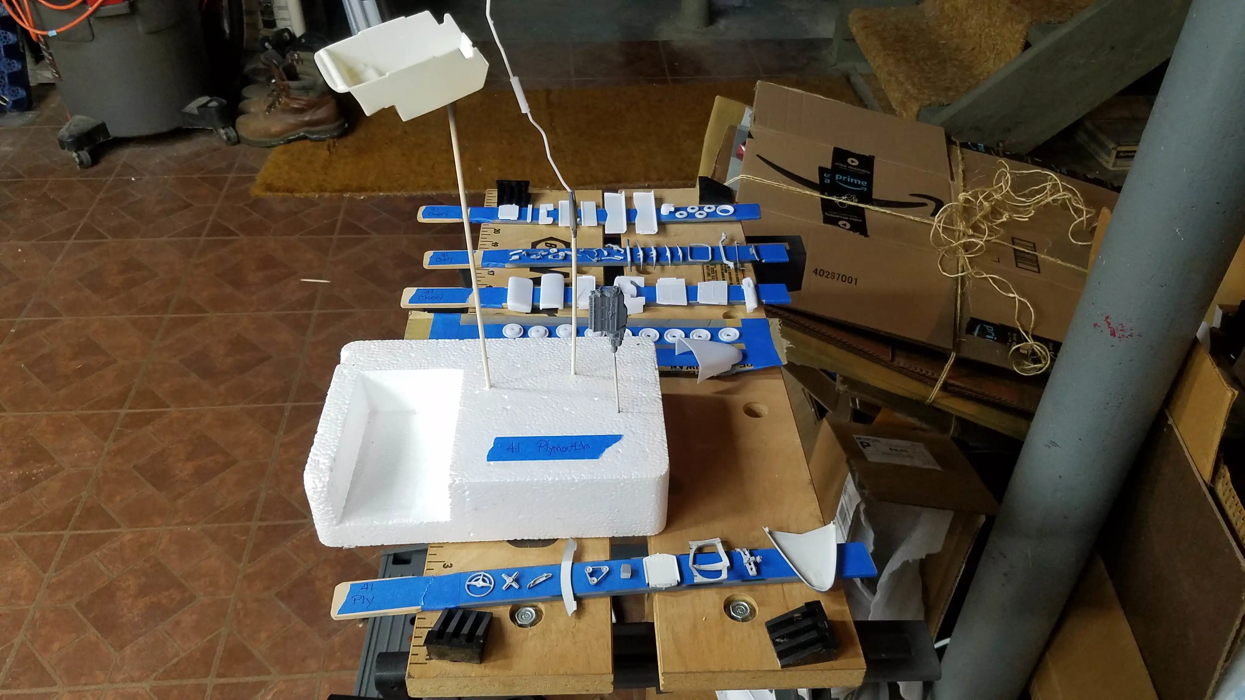
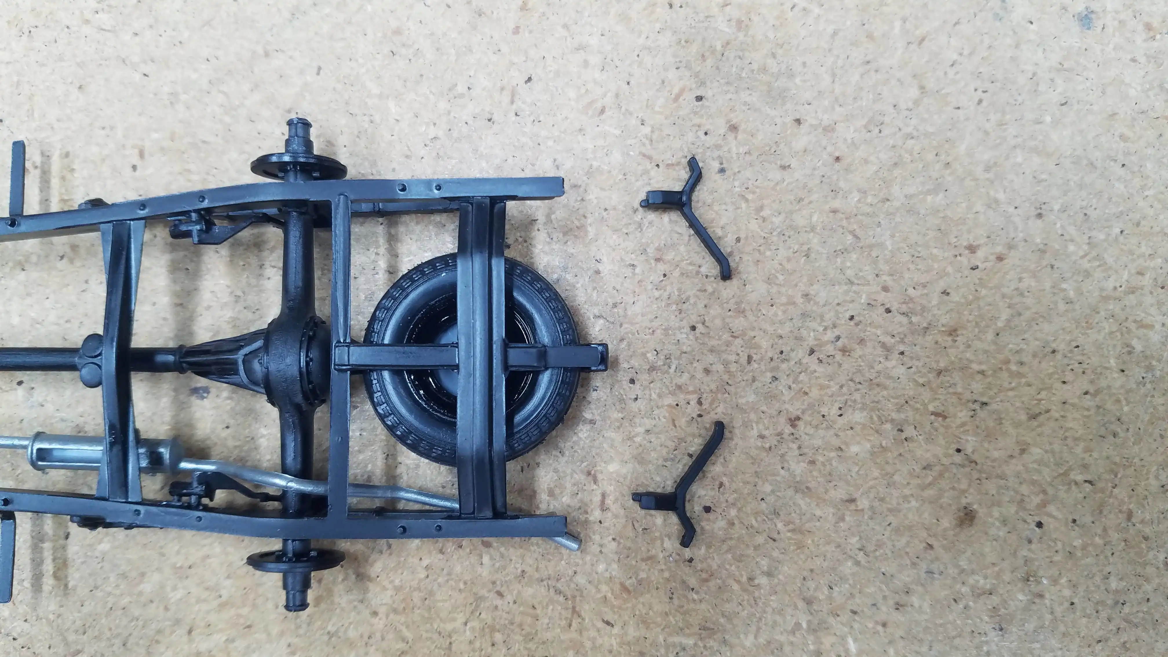
Most of the parts for the chassis and
underside are removed from the sprues and will
be prepped for primer. Areas with injector
pin marks have been marked for removal. This
kit is very clean and there is not a lot of
cleanup.
The cowl vent has been opened. The strip toward the hood is very
thin and I think I need to reinforce it. I'll also be adding a
thin piece of styrene, with an opening the shape of the cowl but
slightly smaller than the main opening to create a small ridge
where the moveable portion of the vent would rest on when closed.
The styrene of this kit is soft and [gummy] (my word) and was
very difficult to cut open. I started by using the back side
of my Exacto blade, but was getting nowhere, fast. I then bought a
Tamiya 0.15mm Fine Engraving Blade and the handle for the blade. It
was working really well until it broke. They're not cheap. Near
$25.00 each. But it was working better than the back side of
an Exacto blade and they work really well for panel lines.
I ordered another 0.15mm along with a 0.30mm and 0.50mm
blade. While waiting for them to arrive I used a #80 drill
(0.0135"/0.343mm) bit and drilled closely spaced holes around
the opening in hopes of making a perforation around the opening.
I then used the back side of an Exacto blade and then when the Tamiya
Fine Engraving Blades arrived, I finished the opening with the 0.30mm
blade. Using these two tools, the vent cleanly popped out.
I'm working on the 1941 Plymouth 4-passenger coupe and the
1941 Chevy Pickup at the same time. The parts for these
two models have been primed; therefore, the parts shown
in this and the following photo's are a combination of the
parts for both kits. After the primer had been applied
several small flaws that were not seen before the primer
was applied could be seen. These small flaws will need to
be repaired. After the the repair, a second coat of primer
will be applied.
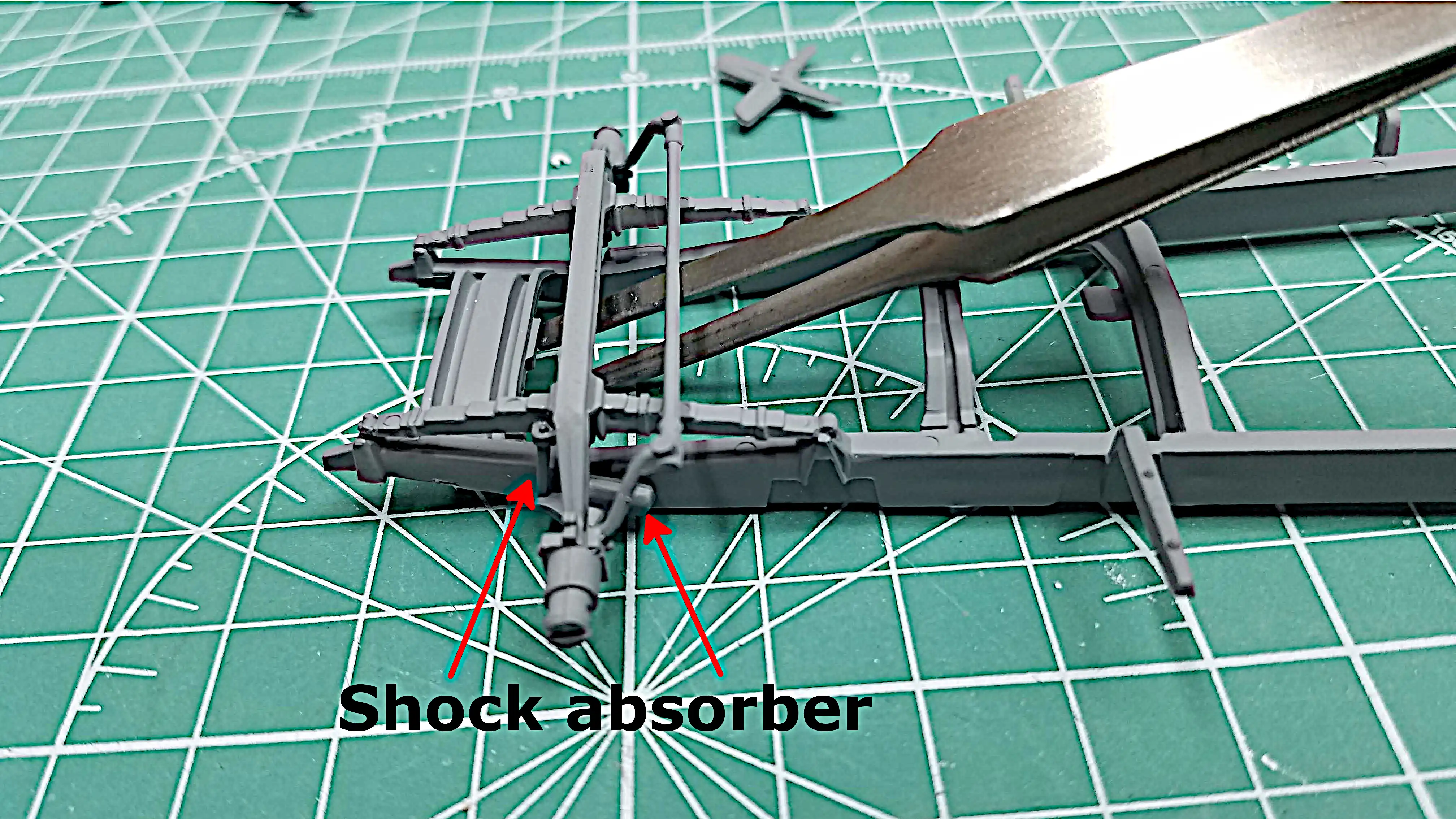
I started assembling the front suspension.
So far, the hardest part was keeping the tie
rod in place. A tweezer is being used to
hold the tie rod in position while the glue
sets up.
The frame has been painted, the front suspension and
steering rod is mounted, the exhaust pipe and muffler
are installed but not glued. The exhaust pipe and
muffler had to be installed before the rear axle and
leaf springs. I did not glue it in place so that
I can insure the pipe will correctly line up with
the engine exhaust manifold. The rear shocks still
need to be installed.
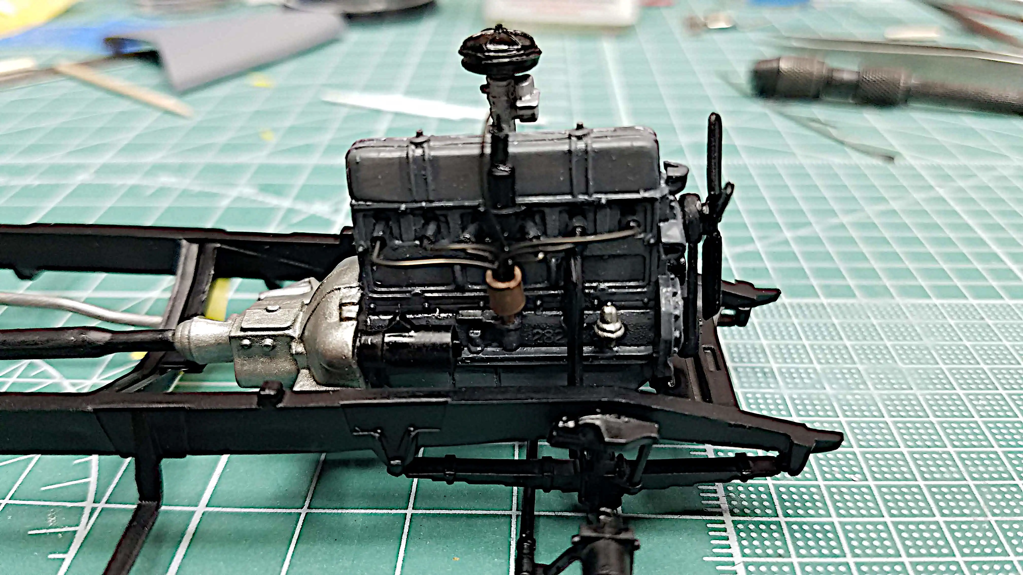
According to what I found online, the factory engine was
painted grey. All I have in my paint stash are flat grey's.
I wanted either a semi gloss or a gloss. I bought some
Mission Model Paint MMRC-010 RC Gray and painted the engine
block, oil pan, engine front and valve rocker cover. The
transmission and flywheel housing will be done using
Model Master Steel. The engine will than be detailed.
(Sorry the image is a bit blurry. I need to invest in
a close-up lens).
The rear shocks have been installed and the frame of the truck
should now be finished and awaiting the engine and drive
shaft. At this time I'm still detailing the engine.
It's amazing what can be seen by the camera that I missed
with my naked eye, but I see another injector mark that needs
to be removed. Ug!
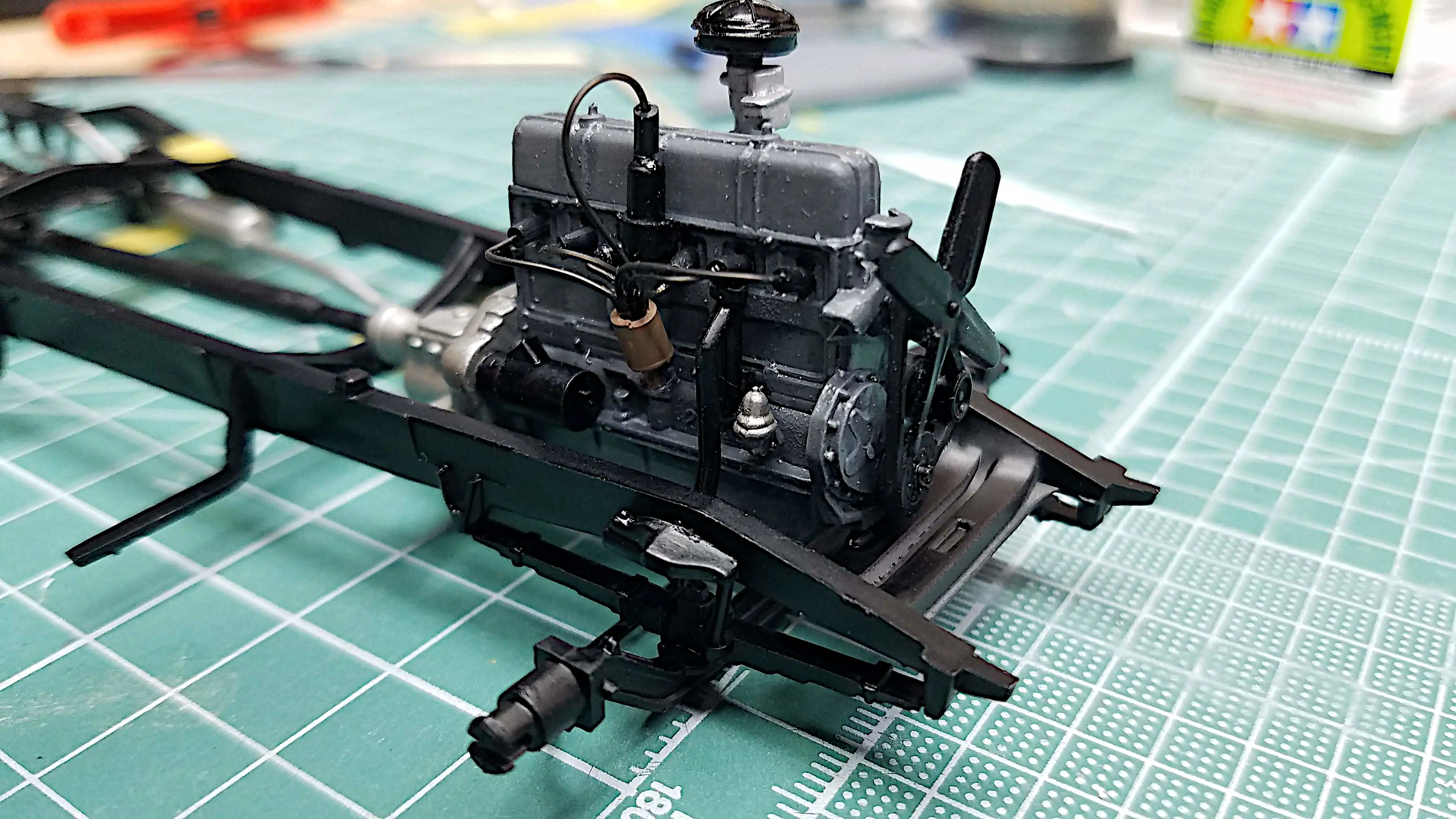
I'm in the process of detailing the engine. I have my
scratch built distributor in place; however, it is not
glued. I'm not sure if I want to use spark plug boots
or ring connectors at the spark plugs. I've seen
pictures of this engine with both connection types.
Some pictures that show boots are straight and some
are right angle. At this point I'm assuming that in
'41, the connections were made with rings, but I'm
not sure and need to do more re
I mocked up the engine, exhaust and drive shaft in the frame to make
sure everything lined up correctly. This photo also shows the completed
spark plug wiring.
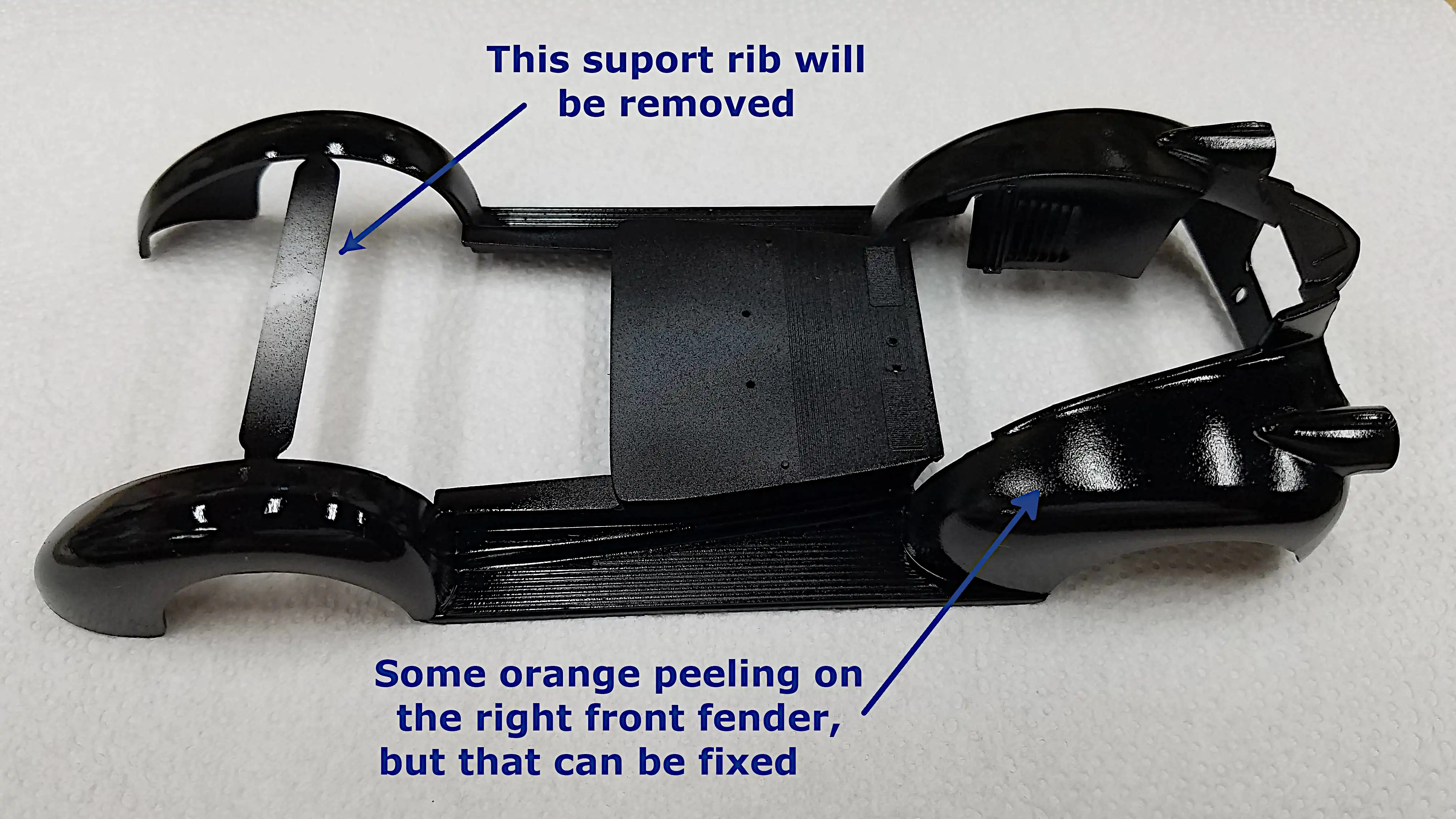
The fenders are sprayed with Tamiya X-1 Black. I have
some orange peeling on the front right fender that shows
up under the bright light for the camera. I'll take care
of that later.
Now that the radiator and the shroud is in place, I
rechecked the fit of the lower body. The
orange peel that was on the front fender was fixed
(reduced) using 3000 grit wet sanding and Novus #2
Fine Scratch Remover and #1 Plastic Clean & shine.
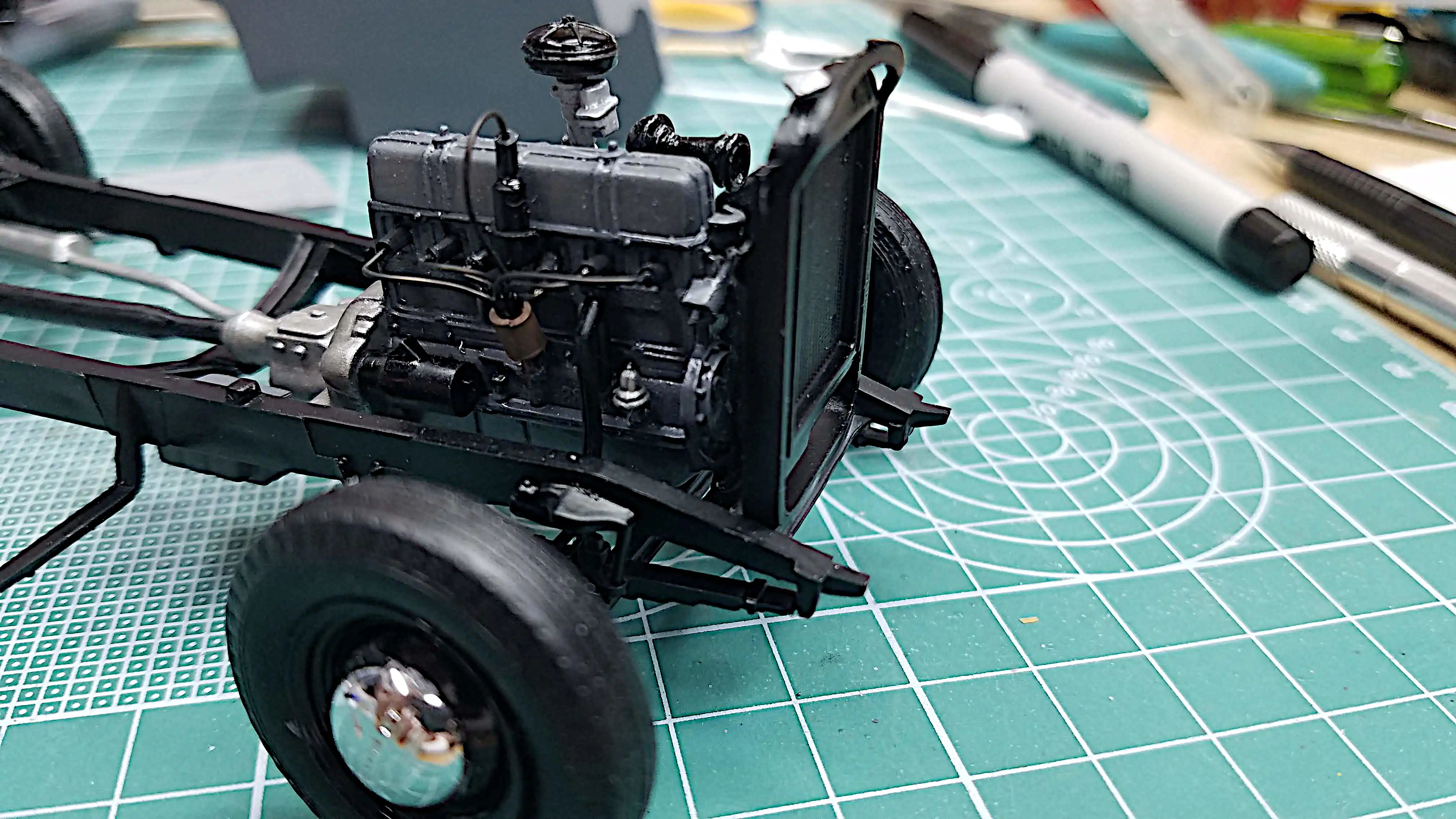
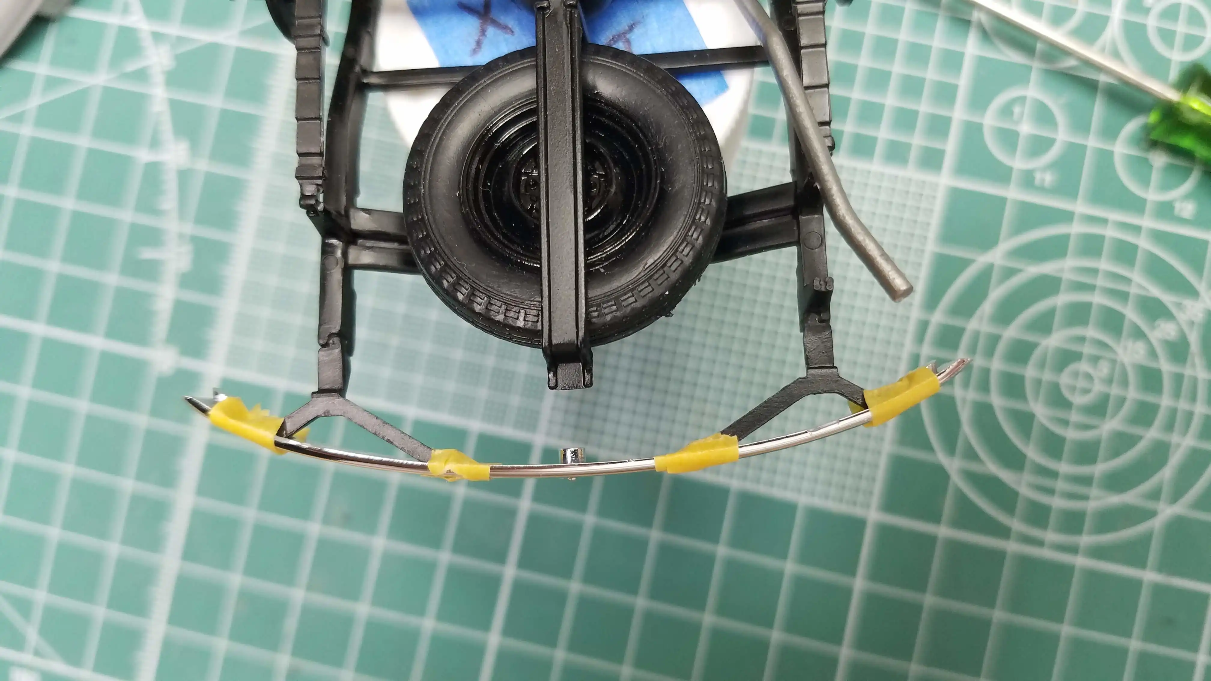
The upper and lower radiator hoses were made and
installed. I used
Detail Master DM-1425 Coolant Hose
. I used it a-bit different than what some modelers use
it. Since this coolant hose is simply, about 18 AWG
(American Wire Gauge) wire, I removed the wire from the
insulation. I than inserted 18 AWG solid soft drawn
copper wire. The solid wire gives the hose some rigidity
and also allows the hose to be more easily formed. The
18 AWG solid wire also fit's better into the mounting holes
on the radiator and engine block.
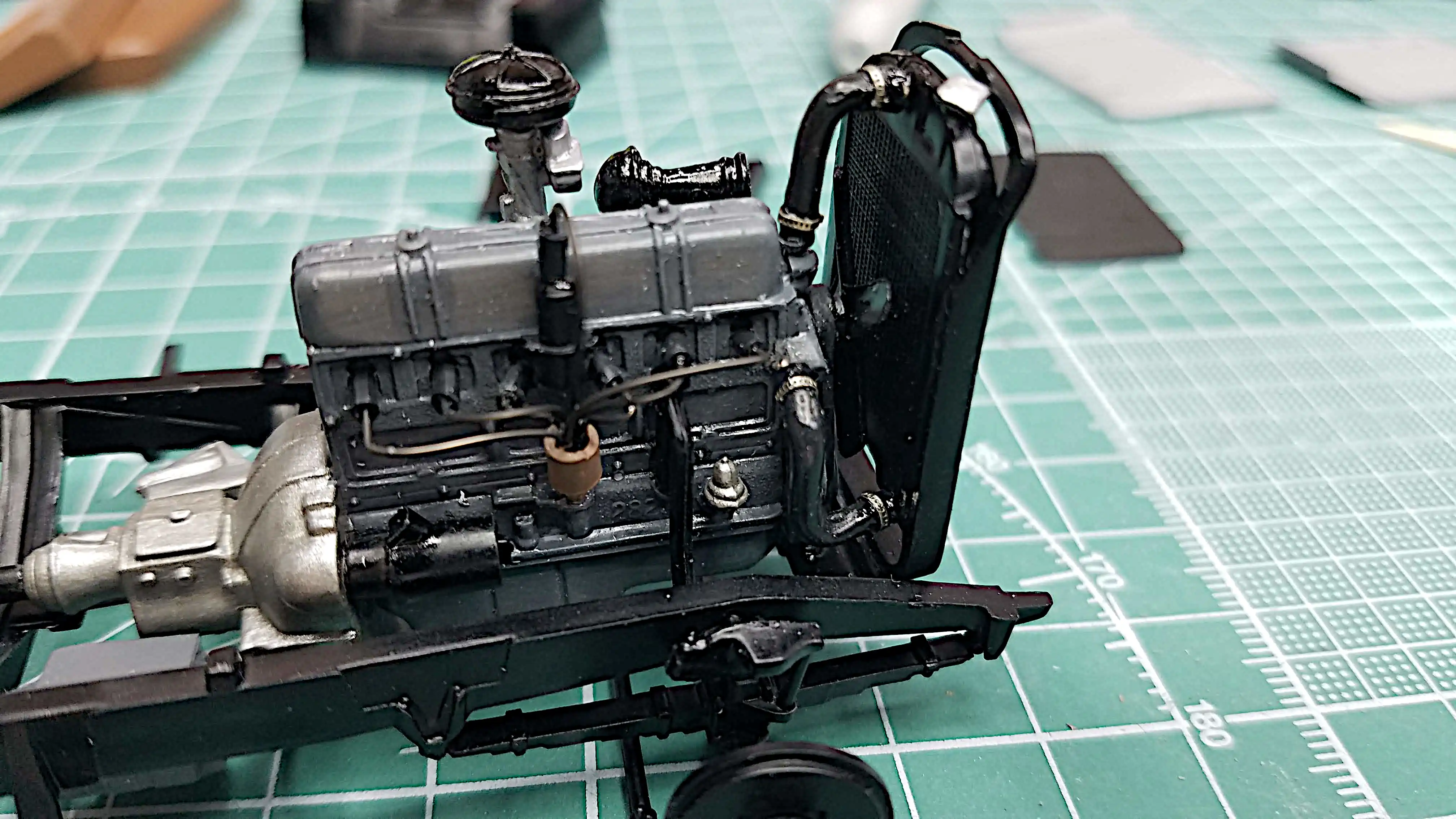
Once I had the hoses bent to shape and adjusted to
properly fit, I install the hose clamps. The clamps I
used are photo etched parts from
The Model Car Garage MCG-2001 Vintage
Hose Straps
. I simply wrap the photo etched strap around the hose
and apply a small drop of Loctite on two or three
locations. When the Loctite is dry I install the hoses.
I had to put the cab in a 91% Isopropyl (IPA) bath
to strip the pain. The clear coat I put on ran. I
tried sanding it, repainting, sanding, repainting
and applied another coat of clear, but you could
still see where the runs were. That's when it went
into the bath.
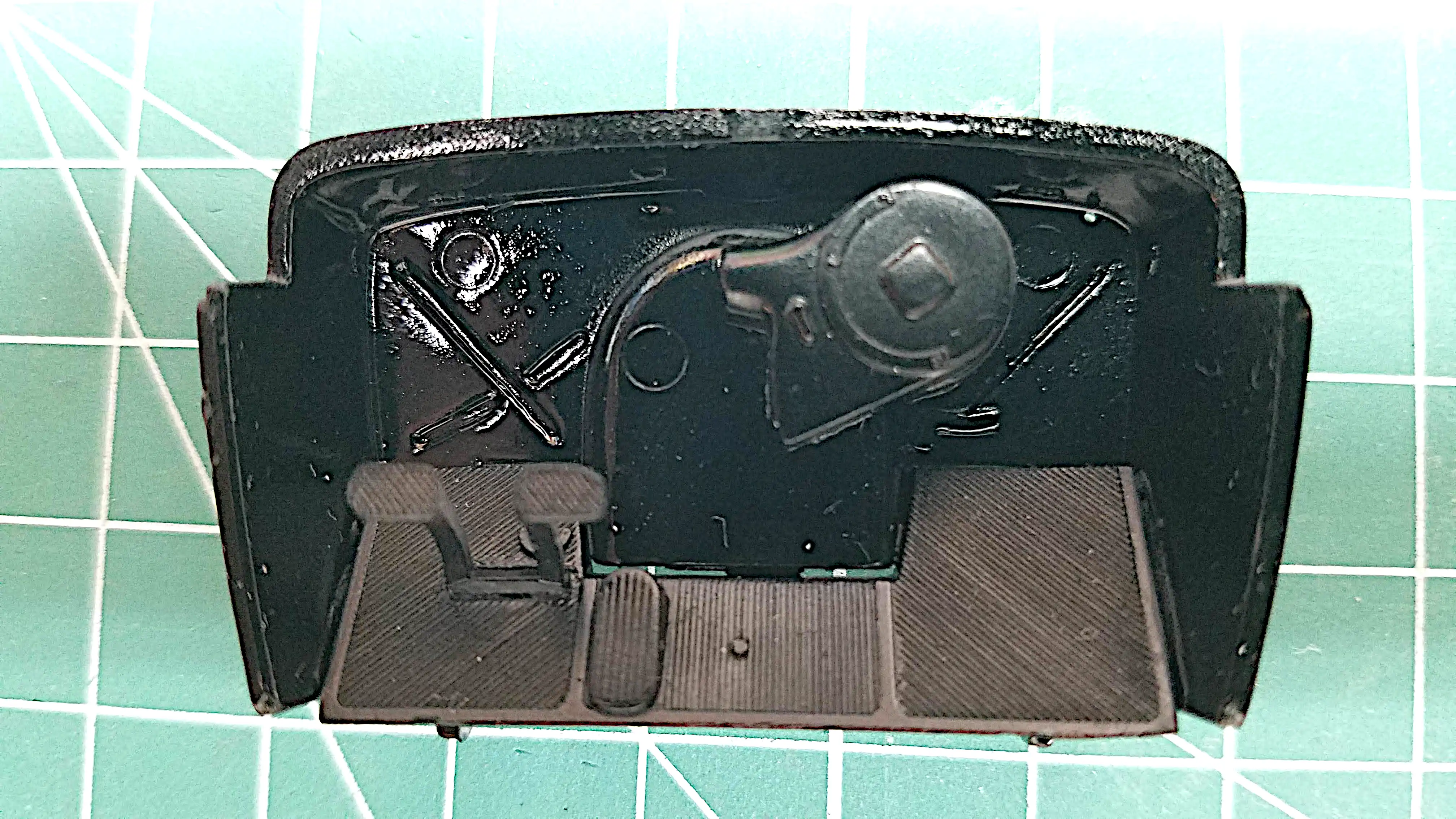
The dash board is finished and ready to install. The
gauges are a decal with a clear plastic gauge cover.
I simply used a small black sharpie to put just a small
highlight on the knobs and a silver sharpie for the
button on the glove box. The crank on the top of the
dash is for the vent cowl.
The truck bed consists of six separate parts with
the tailgate capable of opening and closing. The only
why to assemble it was to tape everything together and
then glue. After all the parts were taped in place, I
used Tamiya fast dry liquid glue to join all the pieces
together.
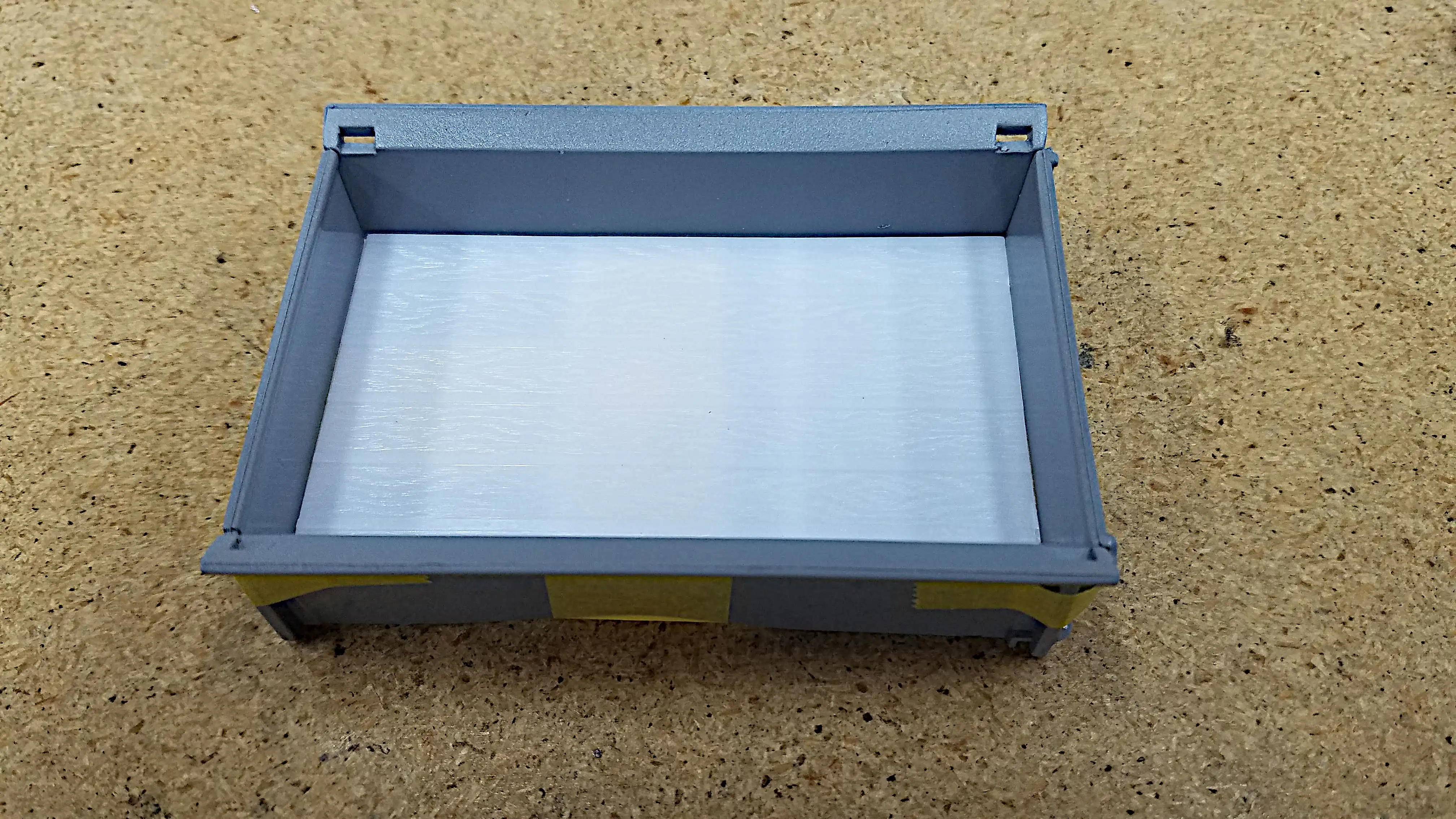
I was not intending to use the bed bottom and therefore
it wasn't painted. I'll be brush painting the bottom of
the bed.
I plan to use balsa wood strips for the bed. Here I have
the wood laid in the bed. They are not trimmed to actual
length yet. When the wood is laid in place I plan to use
the photo etched seam covers that came with the
Detail Master DM-2900 Real Truck Wood Bed Kit
. The kit comes with a sheet of balsa wood, but I think it looks
better with individual boards. The balsa that I'm using is
0.25"/6.35mm wide by 0.066"/1.67mm thick. In 1:25 scale, the
boards would be close to 6" x 1.5". They are the same size as
what is molded into the bed floor.
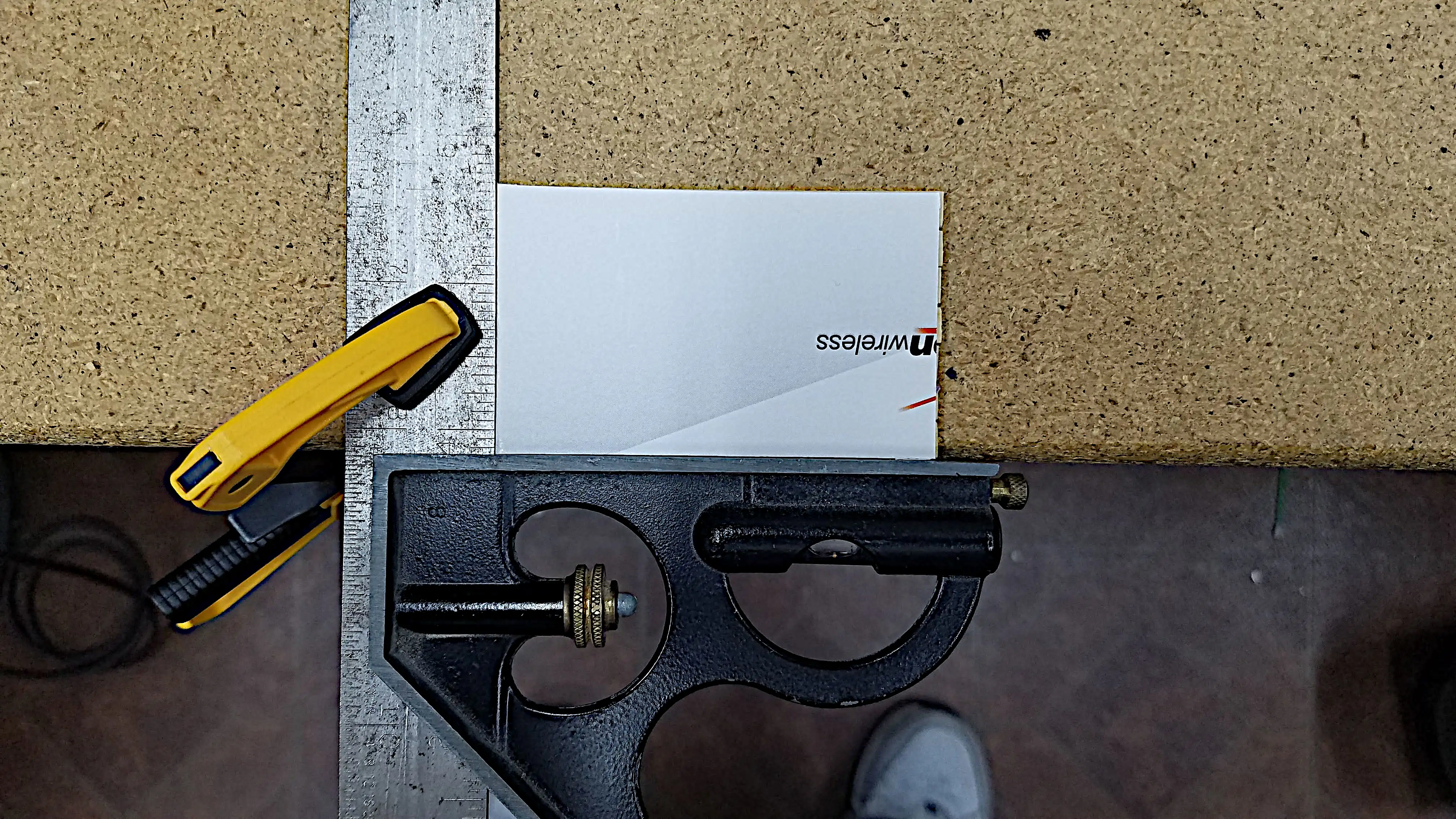
I built the wooden bed by first cutting a piece of
heavy paper or thin cardboard the size of the bed
and approximately 0.015"/0.39mm thick. Make sure
all sides are square and parallel and that it fits
snuggly in the bed without distorting. I then clamp
my combination square to the edge of the bench,
place the cardboard into the corner of the square
and tape the exposed corner to the bench;
tape not shown.
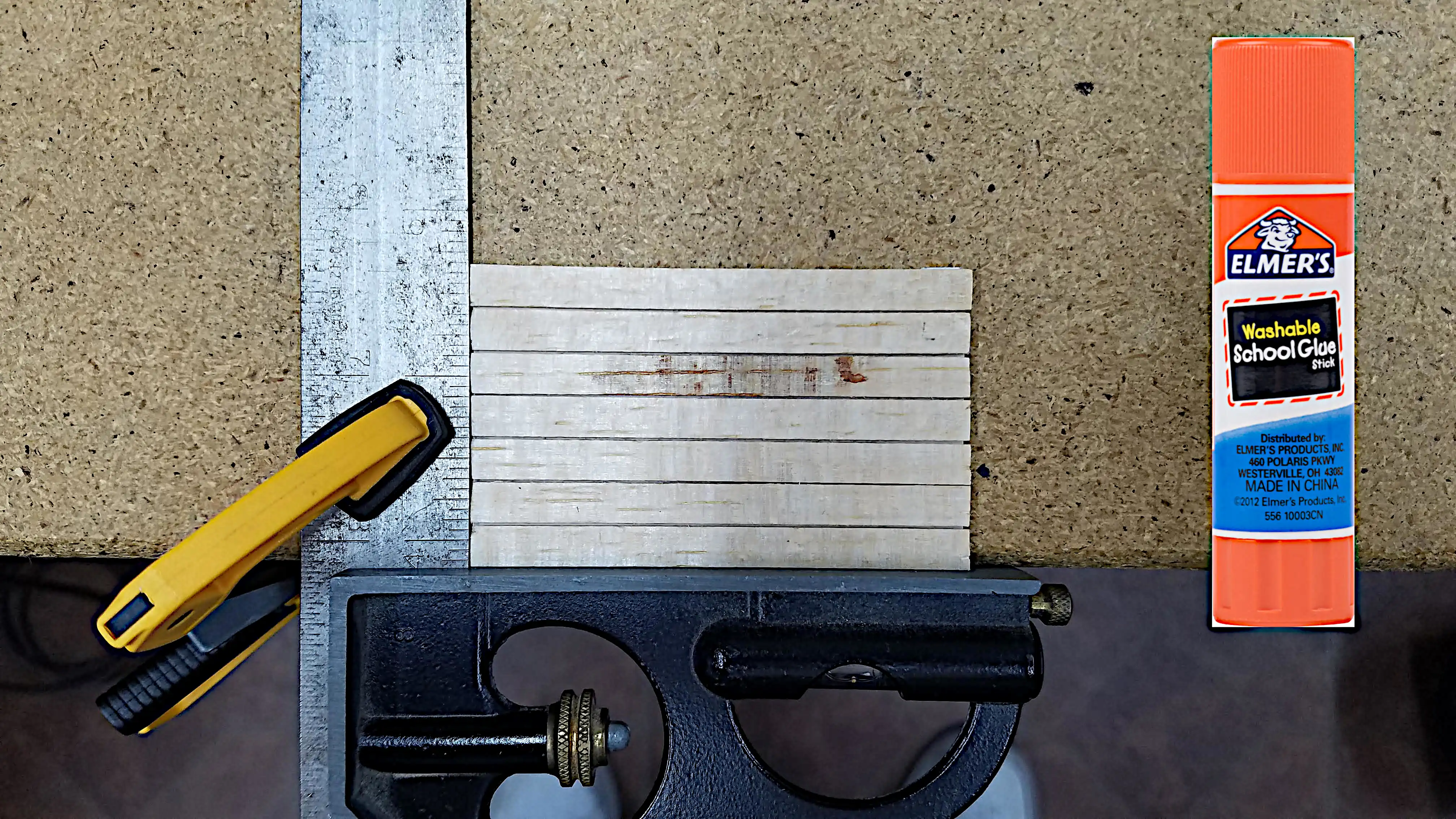
This photo shows the completed bed. I purposely
selected Balsa wood that had a lot of grain to make
it look more realistic. Balsa wood is very porous and
absorbs glue and other runny materials like a sponge,
so I use Elemer's Washable School Glue. It's a stick glue,
which is a paste. I rubbed it onto one side of each
balsa wood strip before placing the balsa word on the
cardboard form.
This photo shows the completed bed; however there are
some simple calculations involved to get the wood strips
to fit properly. In this build my truck bed is 1.9"
wide. It takes 7 strips of 1/4" balsa to spread across
the bed: 7 strips x 0.25" = 1.75". That leaves 0.15" left
over. There are 6 joints, so I calculated the gap size
needed between each board to make up the difference;
0.15" / 6 = 0.025". Using a 0.025" shim between each
strip would spread the boards evenly across the bed; however,
again, balsa wood is porous and will expand and contract
over time, therefore I also left a gap between the side
of the bed and the wood. That makes for 8 shims. I
recalculated the shim size as 0.15" / 8 = 0.019". I
didn't have a 0.019" shim so I used a piece of the
cardboard I used to make the base, which is 0.015" thick
as shims. I cut 8 strips of the cardboard and used them
as spacers between each strip and the bed while gluing
the strips to the cardboard backing. The result is shown
in this picture.
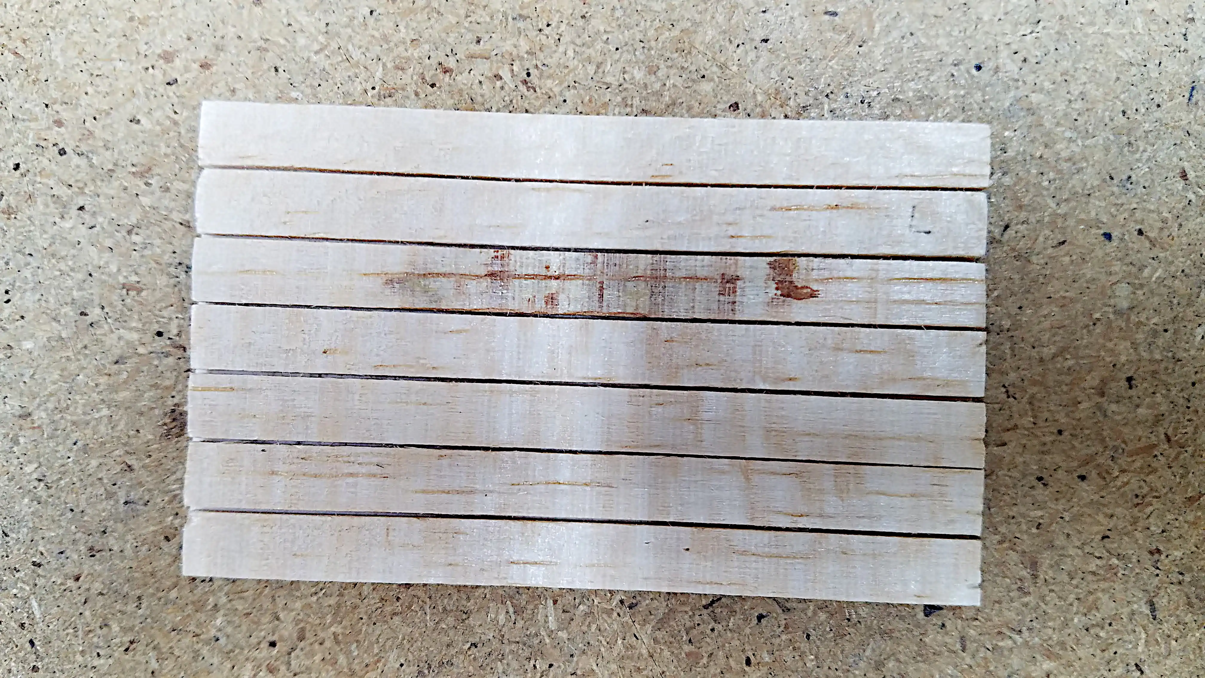
Here is a close up of the finished bed that is also
trimmed to size. I simply used a sanding stick and
my combination square to achieve the proper length.
Personally, I really like the grain on this wood. I
was going to spray a clear coat on it to seal it;
however, I tested some clear coat on scrap balsa and
it did not fare well therefore, I'm leaving it as is.
Maybe later I'll try using some wood oil or some
wood finish on it.
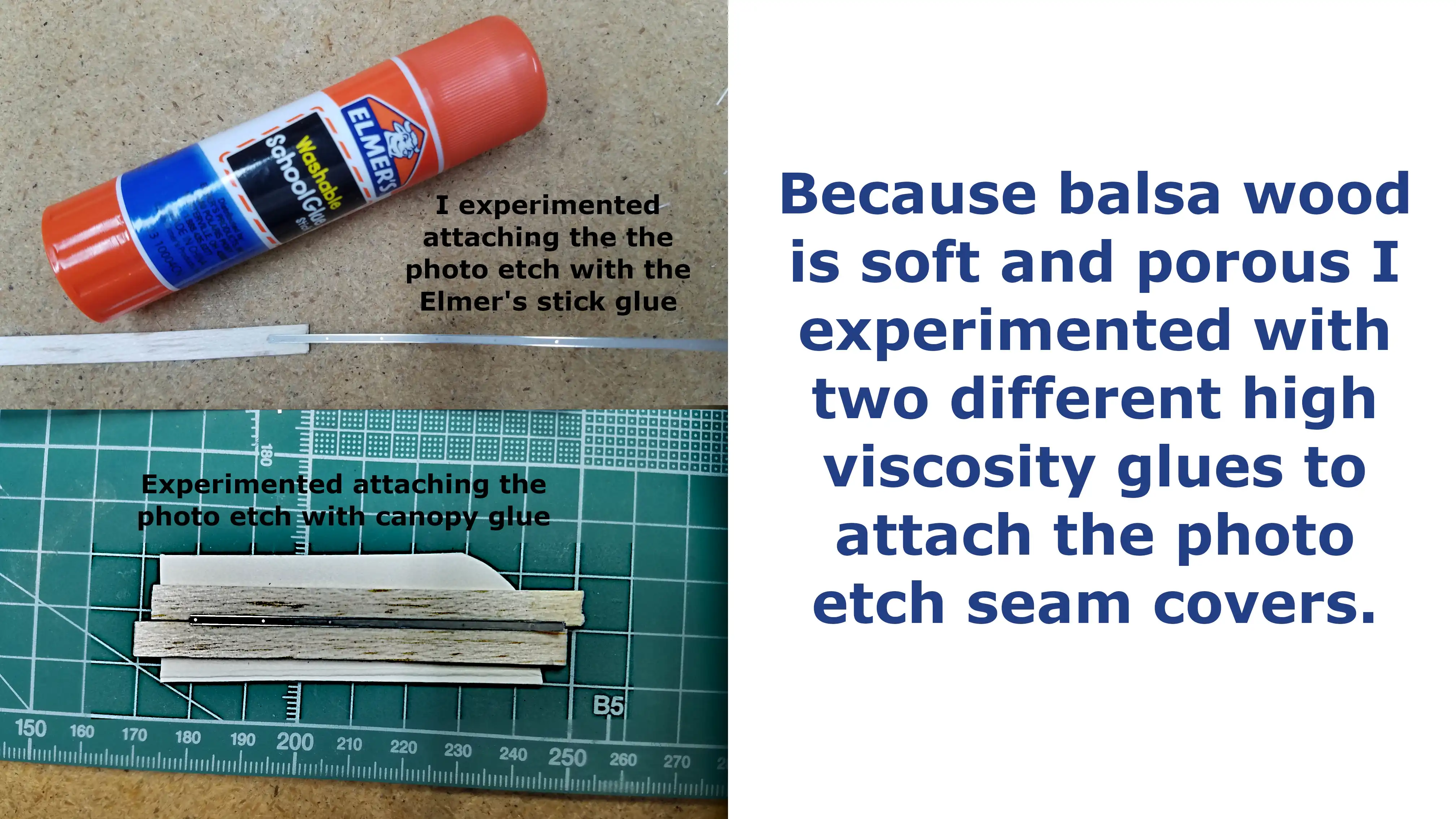
As I stated earlier, balsa wood is very porous and
absorbs liquidity fluids. I need to glue the bed seam
covers in place and knowing the glue needs to have
a high viscosity, I experimented attaching them with
Elemer' stick glue, which I knew does not dry clear,
but has a bluish/purple tint. I wanted a glue that
dried clear so I did another sample using canopy glue.
The top photo is a seam cover glued in place with Elmer's
stick glue. It's difficult to see on the photo, but there
is a light blue tint when the glue dries. The strip
is firmly attached, but I don't like the bluish tint.
The bottom picture is the seam cover glued in place with
canopy glue. When the glue dries it literally disappears
and when I tried to remove the seam cover it also lifted
some of the wood, so I'll be using canopy glue for the
seam covers.
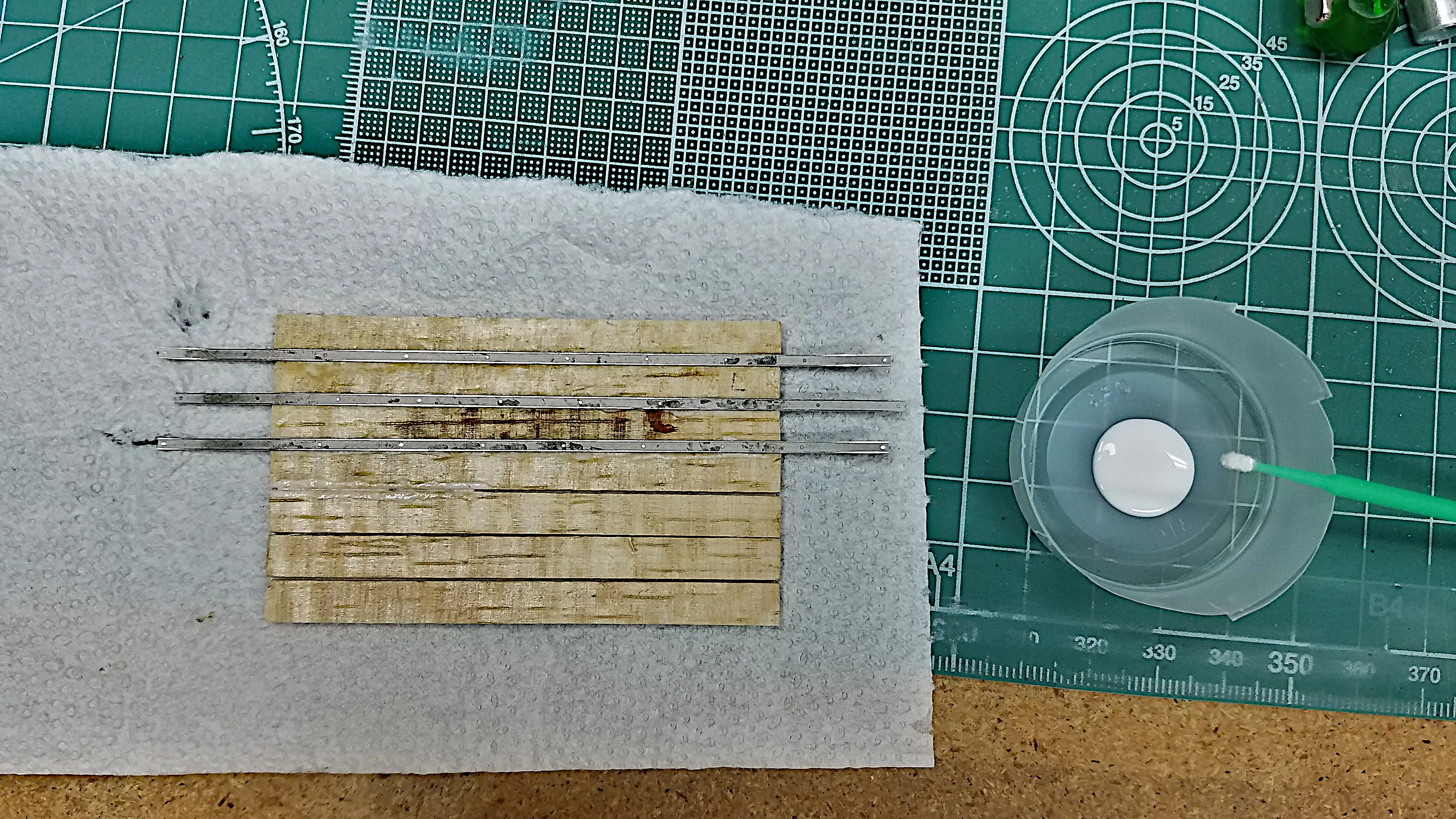
This photo shows the process of gluing the seam covers to
the bed. I put some canopy glue in a small plastic cup and
used a microbrush to apply the glue along the wood joint. I
then simply eye-balled the location of the seam cover. I
used a Q-Tip to press the seam cover to the surface. The
Q-Tip leaves a little mark on the seam cover, but after the
glue dries, running a damp Q-Tip along the cover removes
the mark. When the glue if fully dry, the ends will be
trimmed. The seam covers are made for an 8-foot bed and the
bed of the '41 is 6-foot.
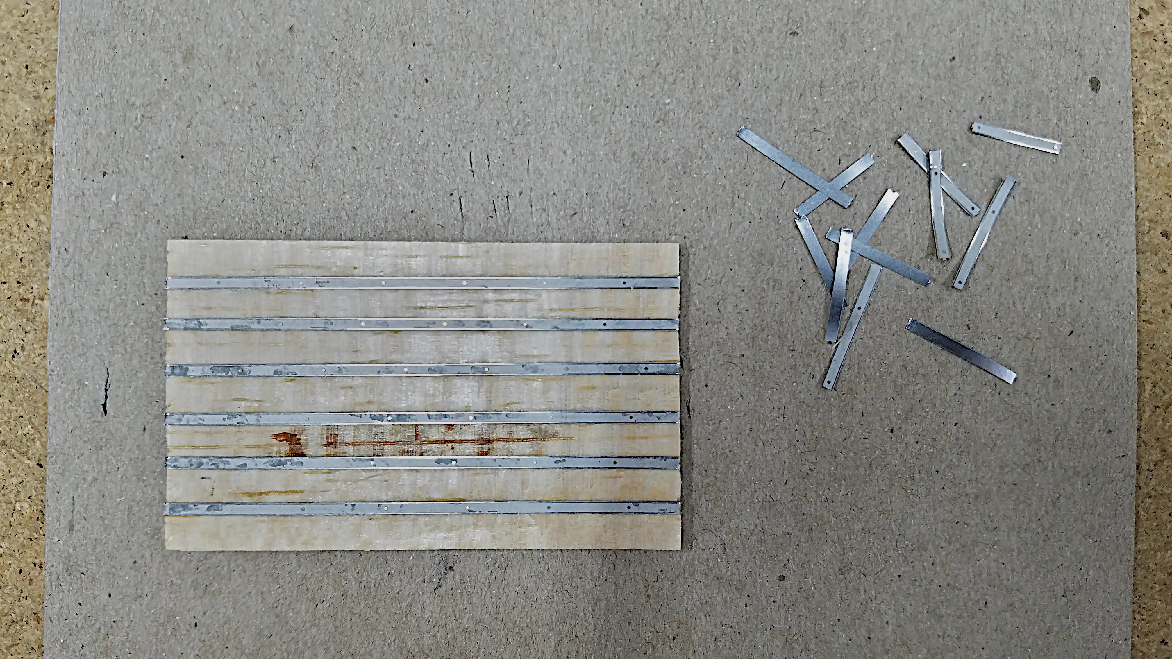
I let the glue on the bed seam cover strips set for 24-hrs.
I then took a Exacto blade, turned the bed, seam covers
down, and trimmed the excess material.
While the glue on the truck bed was drying I worked on the
truck frame. The rear bumper supports need to be mounted;
however, the mounting surface is very small and not well
defined. The next photo shows how I made sure the bumper
mounts would be in the correct location to later mount the
bumper.
I taped the bumper to the mounts and then glued the mounts
to the frame. This should insure that when the bumper is
glued in place, the mounts will be in the right location.
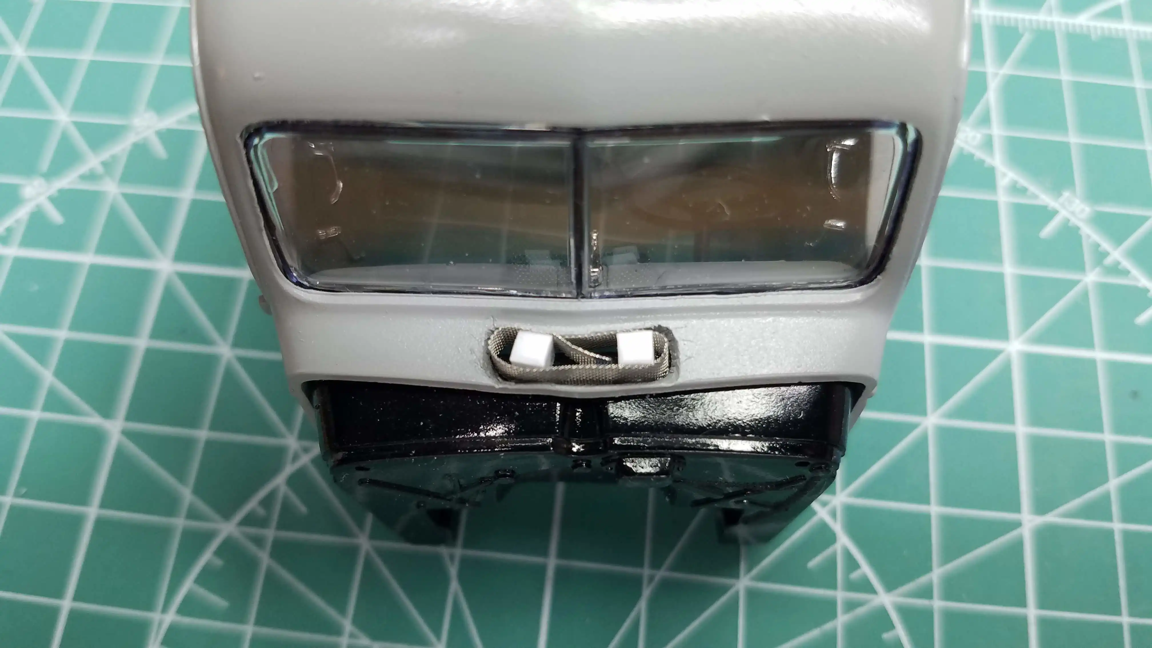
Way back at the beginning of the build, which seems like
an eternity, I had cut the cowl vent open. In this photo
I'm starting to build the screen mesh that shows when the
vent is open. I used
Model Car Garage MCG 703 Stainless Steel Mesh
to make the vent screen.
When the cab was placed on the frame and the hood put
in place, it was very apparent that the cab was leaning
toward the back leaving a gap between the hood and the
cab over the firewall. Also, the radiator brace did not
fit and was not long enough to reach the radiator housing.
When I held the back of the cab up, it not only leveled
the cab, but it also made the hood and the radiator
brace fit perfect. To hold the cab in, what I think is
the correct position, I placed two shim blocks between
the cab floor and the back of the cab, as shown in this
photo. The block I used is
Evergreen #175 0.100" x 0.100" Opaque White Polystyrene Strip
. I made them slightly longer than the cab floor because
when the bed is in place they won't be seen.
This and the next photo show the cab, the bed and the hood
in place. When all the glue dries, the only things
remaining are the bumpers, door handles, gas filler tube,
windshield wipers, side mirror, head lights and license
plate holder(s). These items are ready to go and will
take only a few minutes to install, completing the model.
This and the previous photo show the cab, the bed and the hood
in place. When all the glue dries, the only things
remaining are the bumpers, door handles, gas filler tube,
windshield wipers, side mirror, head lights and license
plate holder(s). These items are ready to go and will
take only a few minutes to install, completing the model.
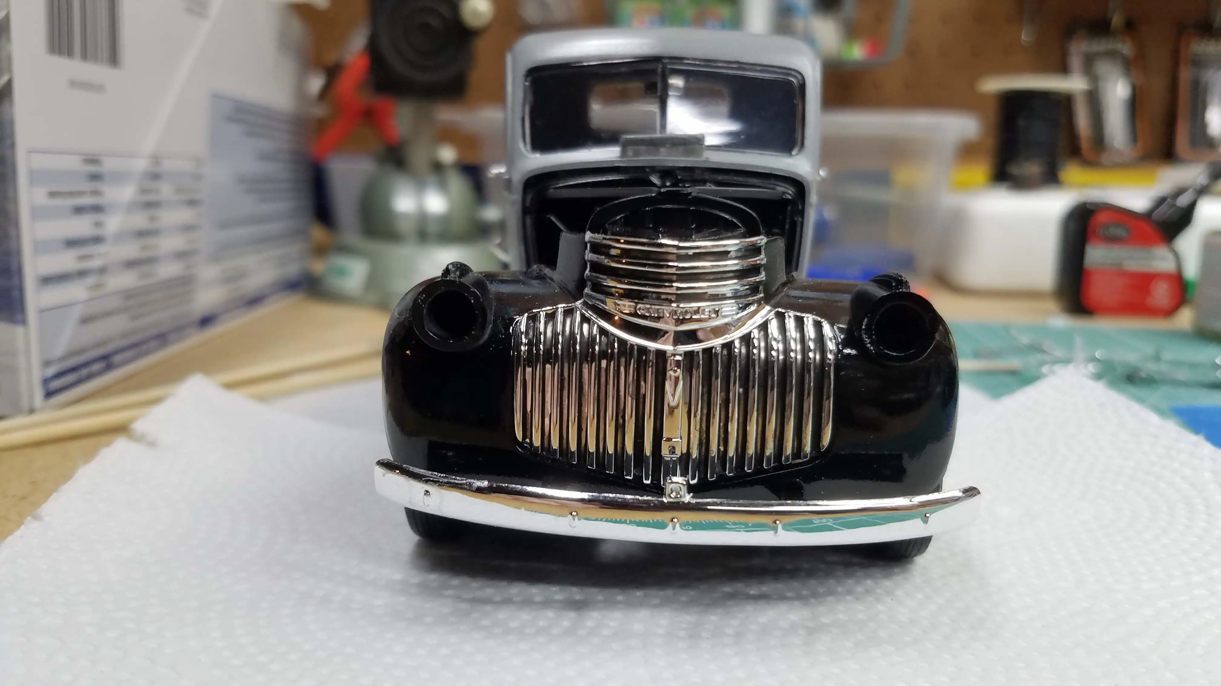
I installed the grill and the front and rear bumpers. The
only parts that need to be installed is the windshield
wiper, the side mirror, the hood handles and the rear
license plate holder with tail light. This truck will
have a Pennsylvania truck license plate on the rear
holder. Pennsylvania does not have front license plates
and therefore I'm either going to leave the license holder
off or mount it and leave it blank.
I make my own license plates by finding a picture of one
that I'm looking for. In this case I wanted a Pennsylvania
1941 Truck plate. I found a picture online that was of
decent quality. I then use
Gimp
to enhance and resize the plate. I normally increase the
number of pixels to 1080px. I then adjust the size to
fit the license plate holder that came with the kit.
Sometimes, especially with old plates, the image cannot
be scaled to fit the plate holder while keeping the
perspective correct. In that case I make my own plate
holder and also make sure everything is properly scaled.
In this case the plate holder measured 0.490" x 0.238"
(12.45mm x 6.05mm). In 1:25 scale it is: 12.25" x 5.95"
(300.15mm x 151.13mm). That's almost exactly what an
actual 1941 PA plate measure's. I print the plate on my
color laser printer, cut it out and use Elmer's Washable
School Glue to glue it to the holder.
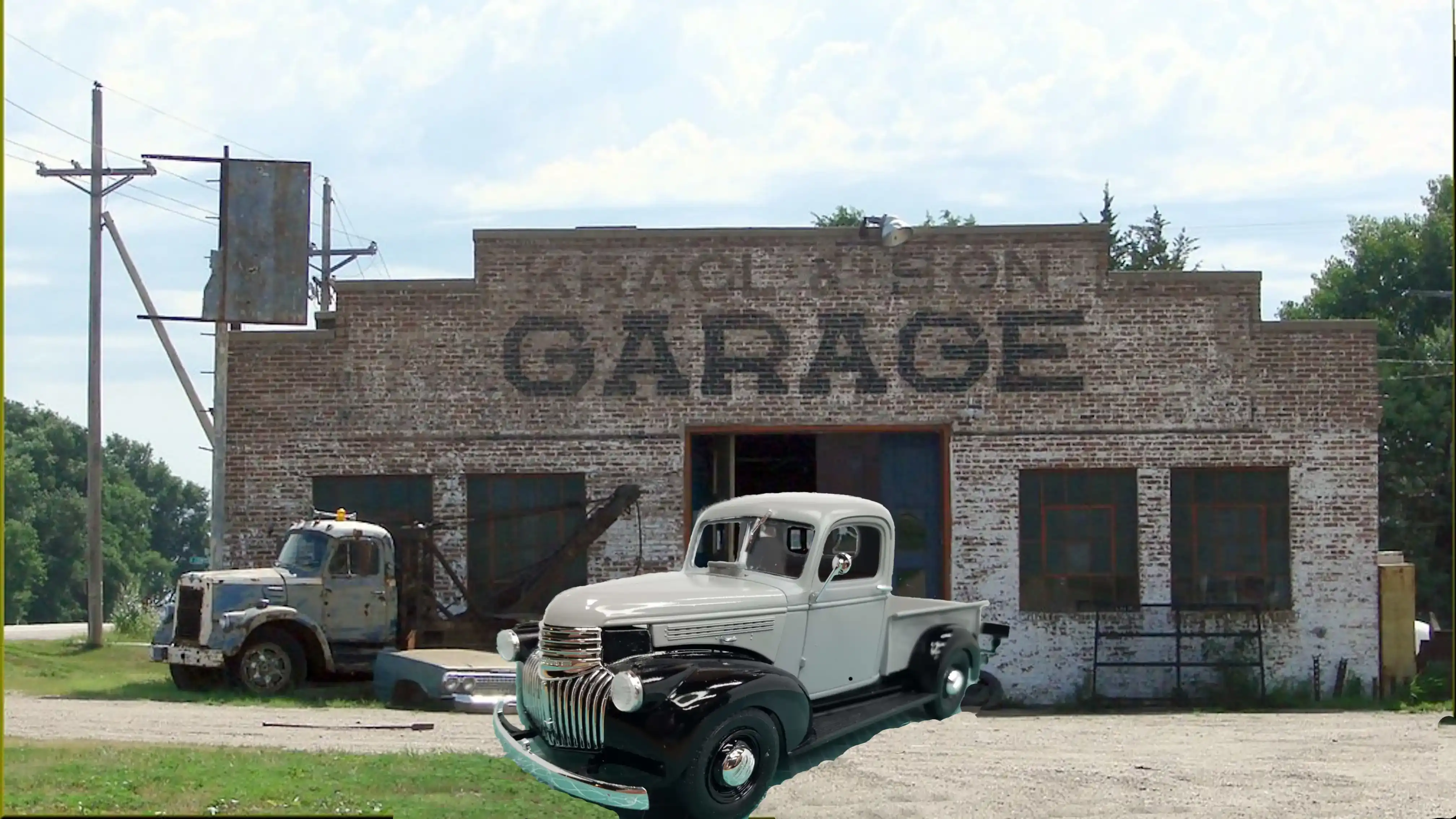
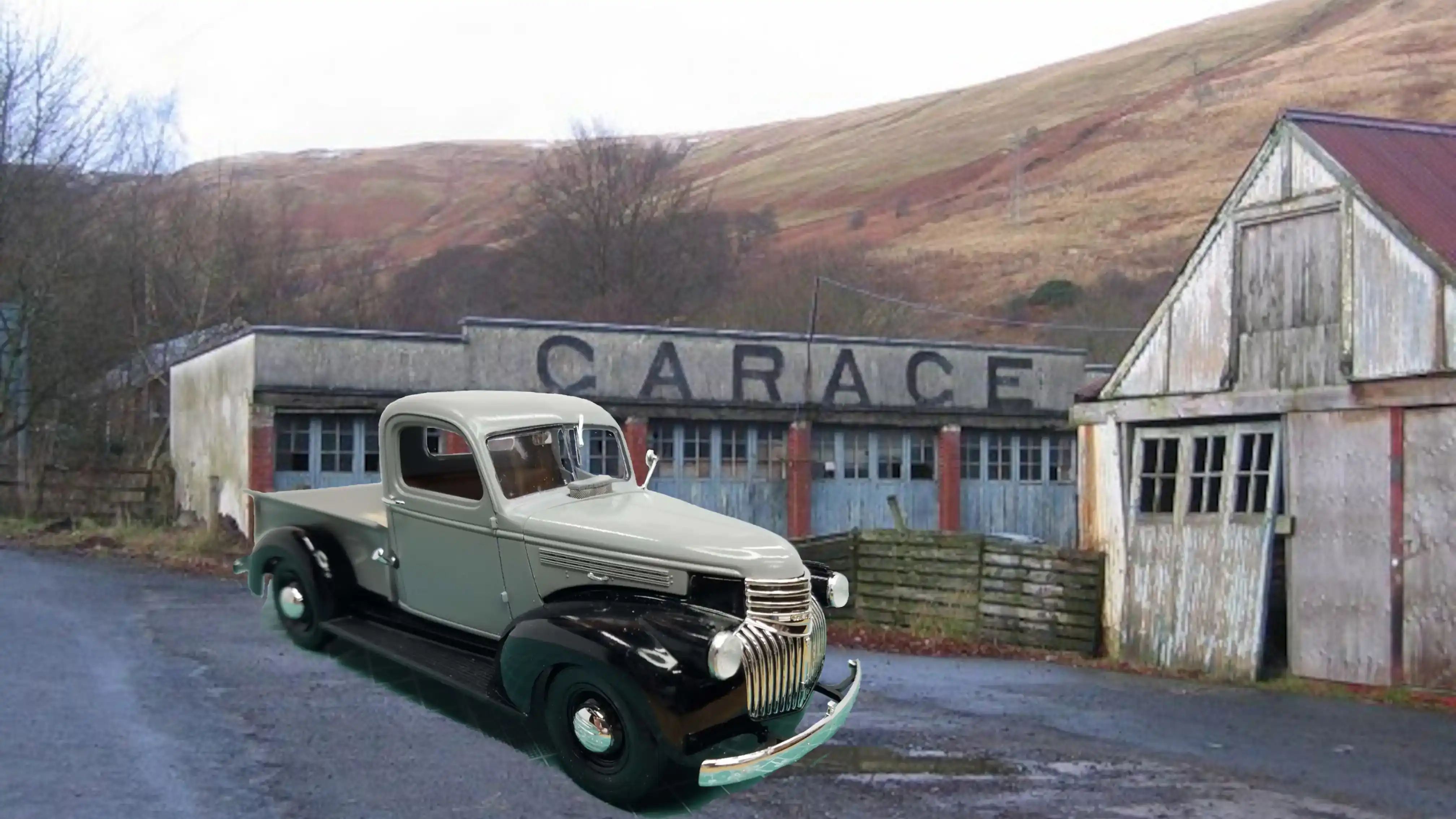
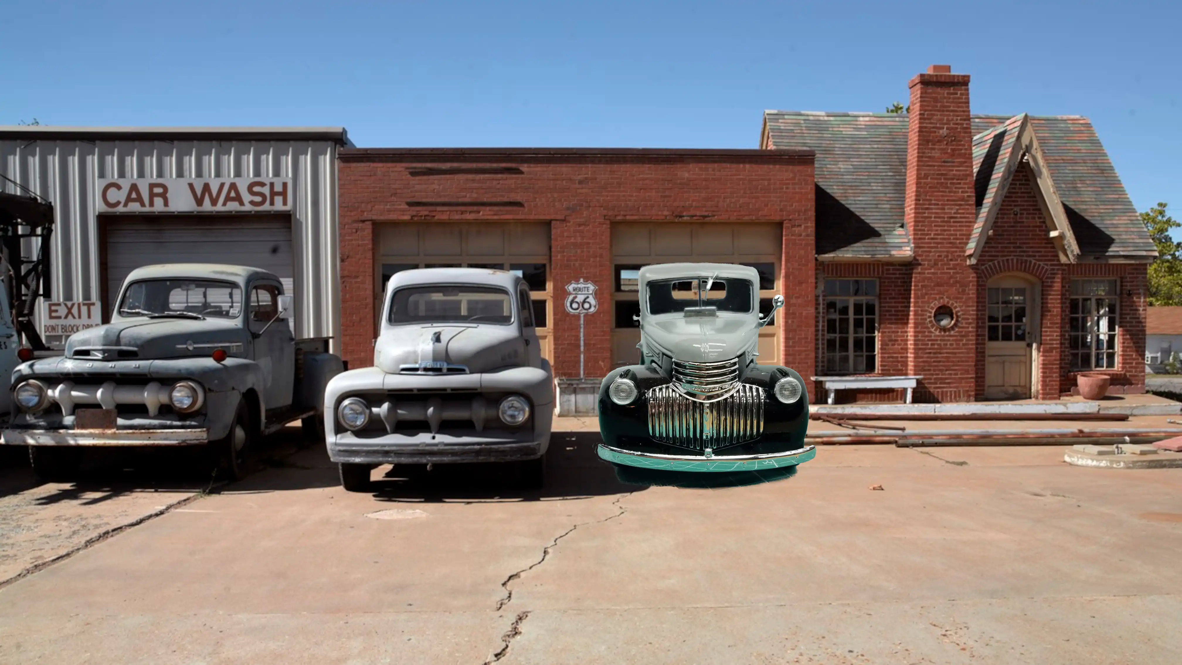
This photo starts a series of photos of the finished
build. I also attempted to place the finished model
into a pictorial scene, but some of the angles were
not correct and I didn't reshoot the model at the
different angles.
I'm learning how to place an image within an image. I'm
still working on how to adjust the angles and the
rotation when the photo is not at the angle or rotation
desired.
Gimp
is a good program that is free; however, the learning
curve is very steep. I'm still climbing that curve.
I'm learning how to place an image within an image. I'm
still working on how to adjust the angles and the
rotation when the photo is not at the angle or rotation
desired.
Gimp
is a good program that is free; however, the learning
curve is very steep. I'm still climbing that curve.
I'm learning how to place an image within an image. I'm
still working on how to adjust the angles and the
rotation when the photo is not at the angle or rotation
desired.
Gimp
is a good program that is free; however, the learning
curve is very steep. I'm still climbing that curve.
I'm learning how to place an image within an image. I'm
still working on how to adjust the angles and the
rotation when the photo is not at the angle or rotation
desired.
Gimp
is a good program that is free; however, the learning
curve is very steep. I'm still climbing that curve.

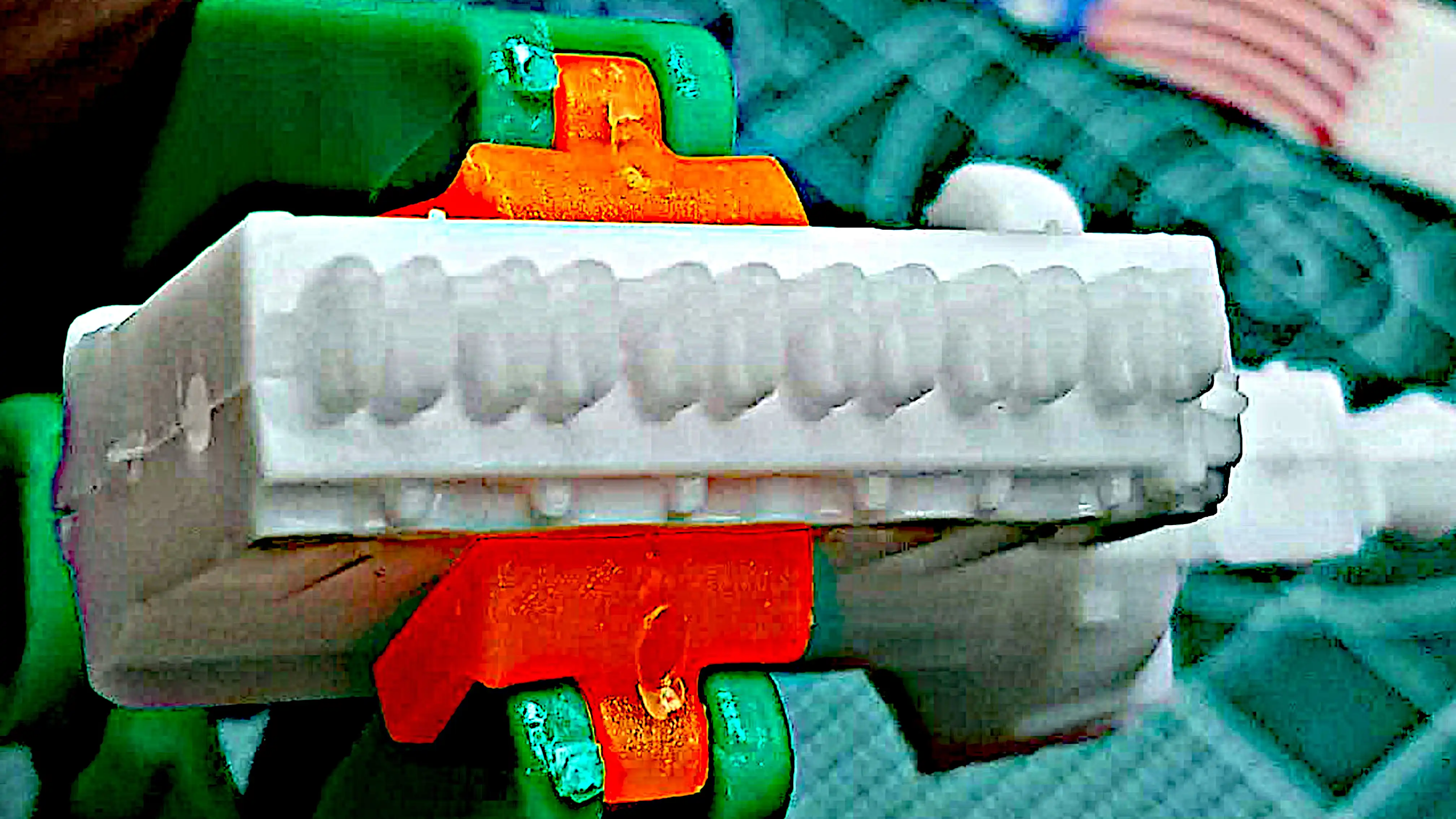
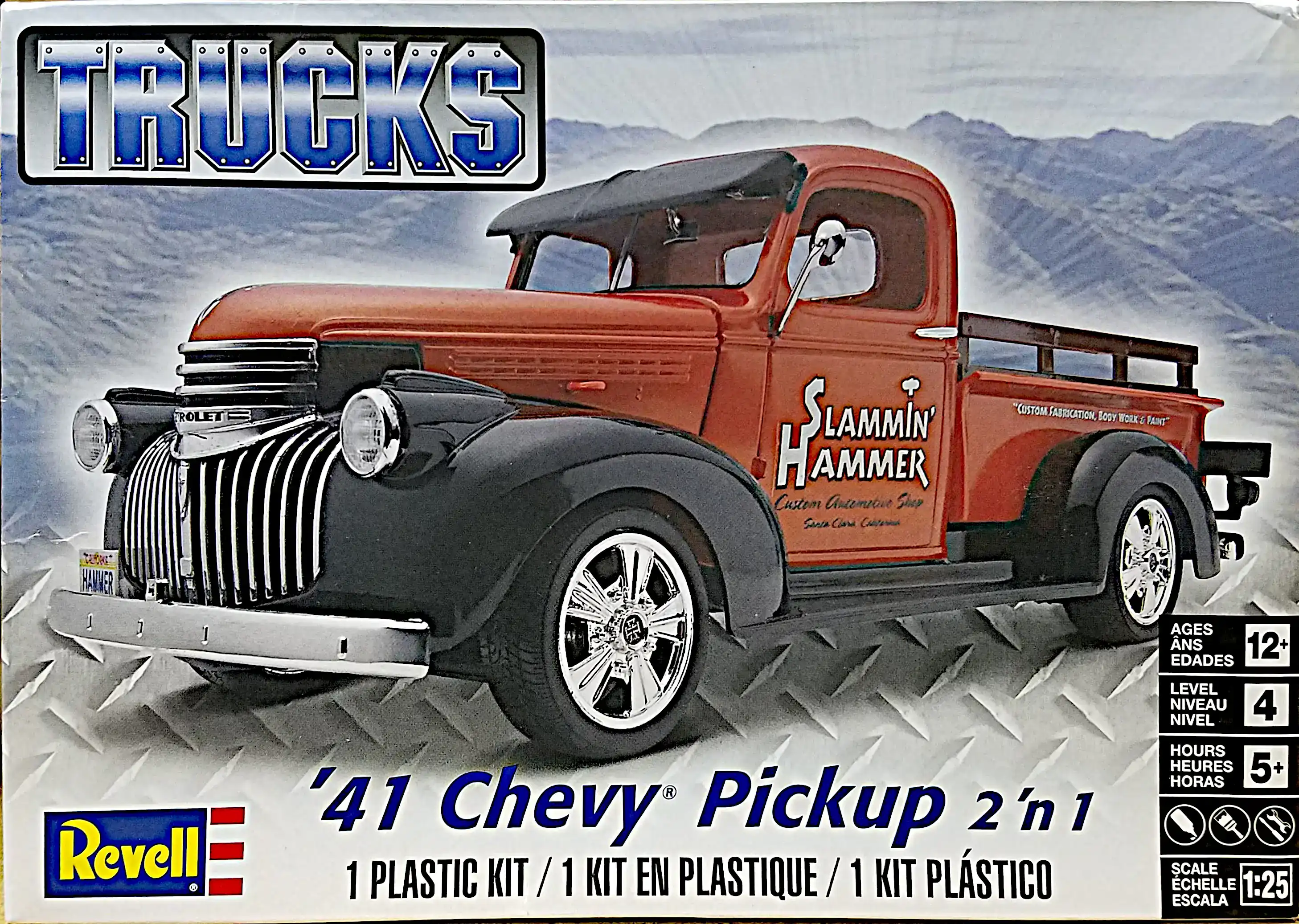 1941 Chevy Pickup Box Art
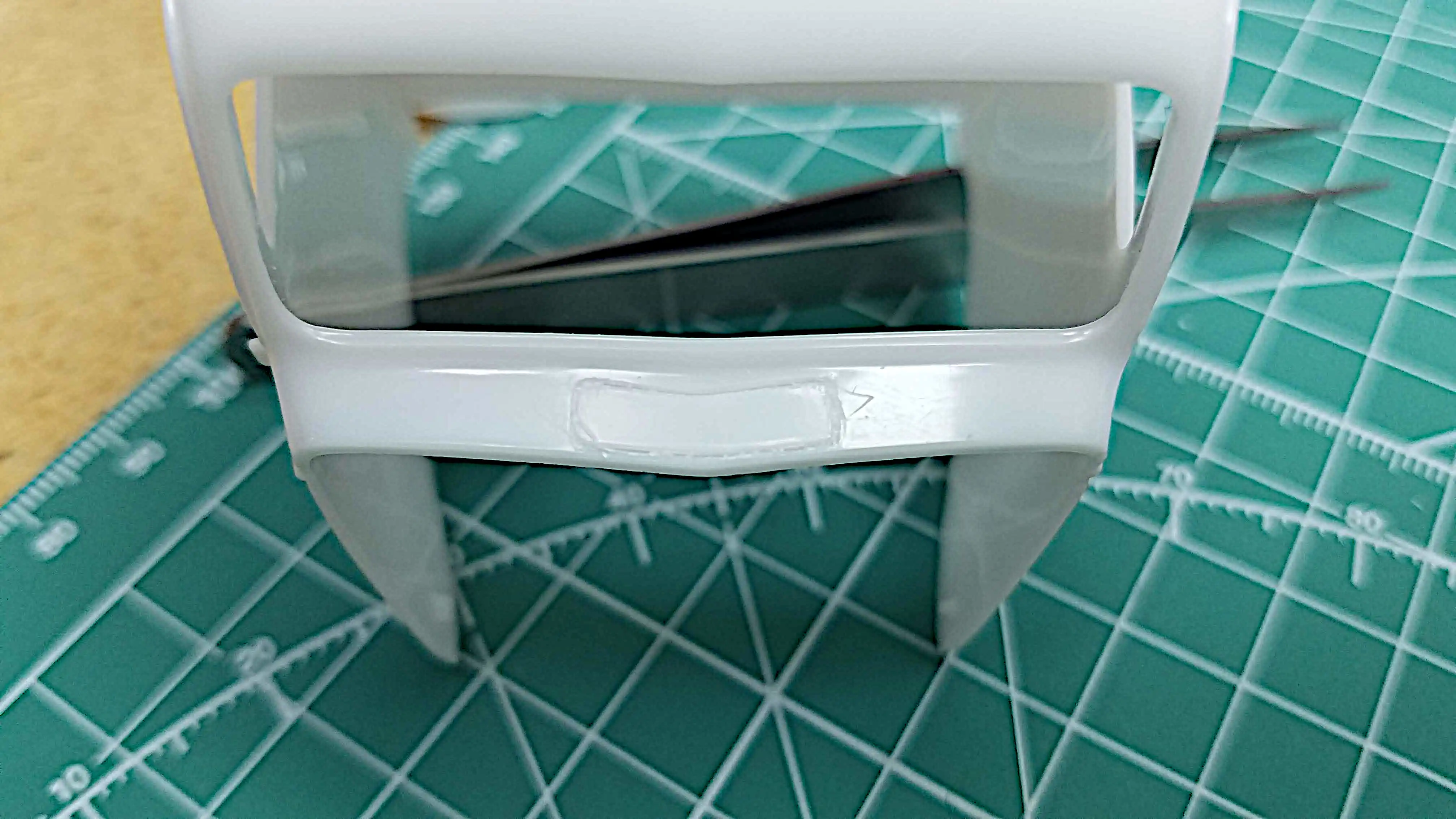 Plan to cut open the cowl vent
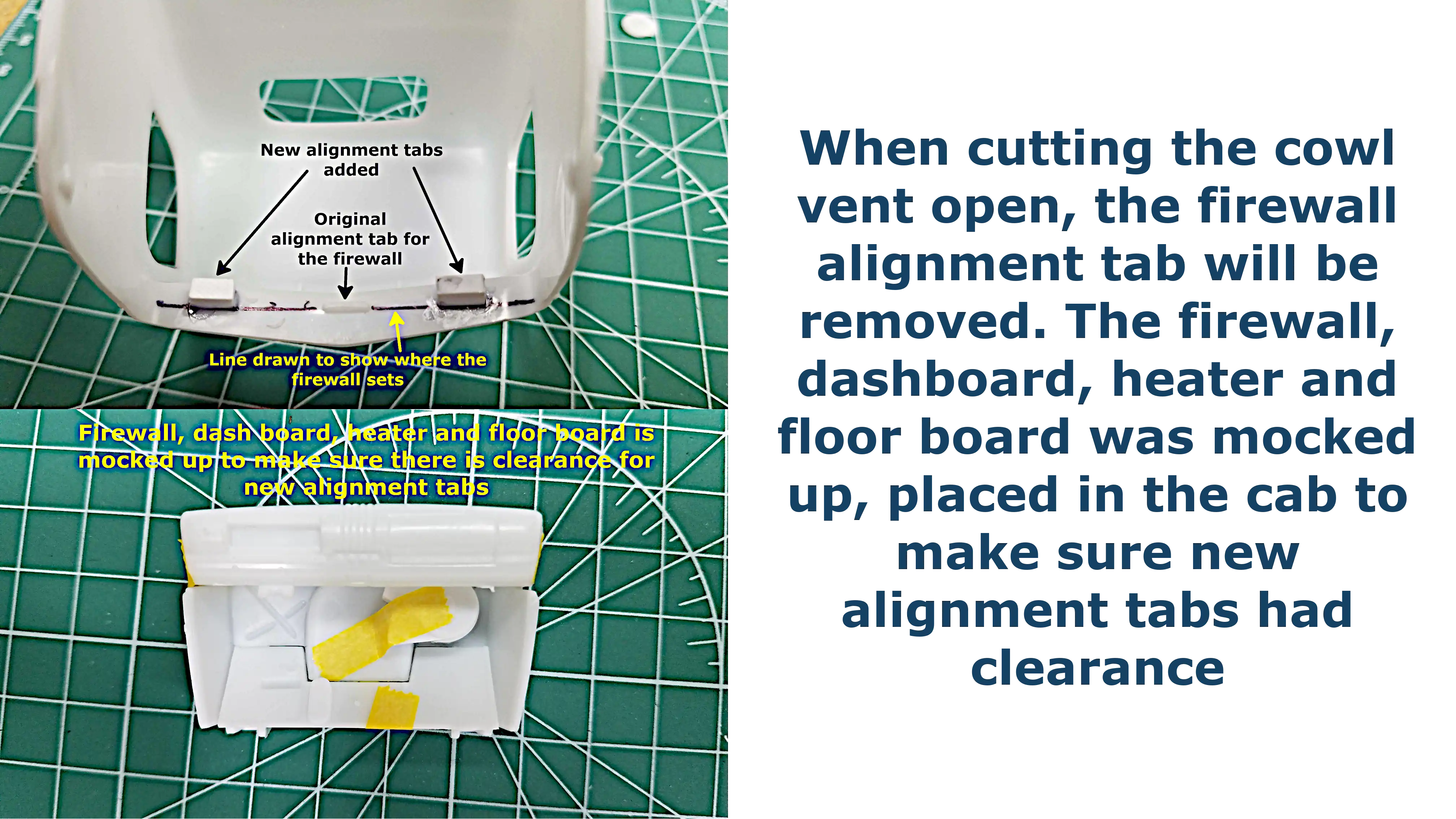 Modification to firewall alignment tabs
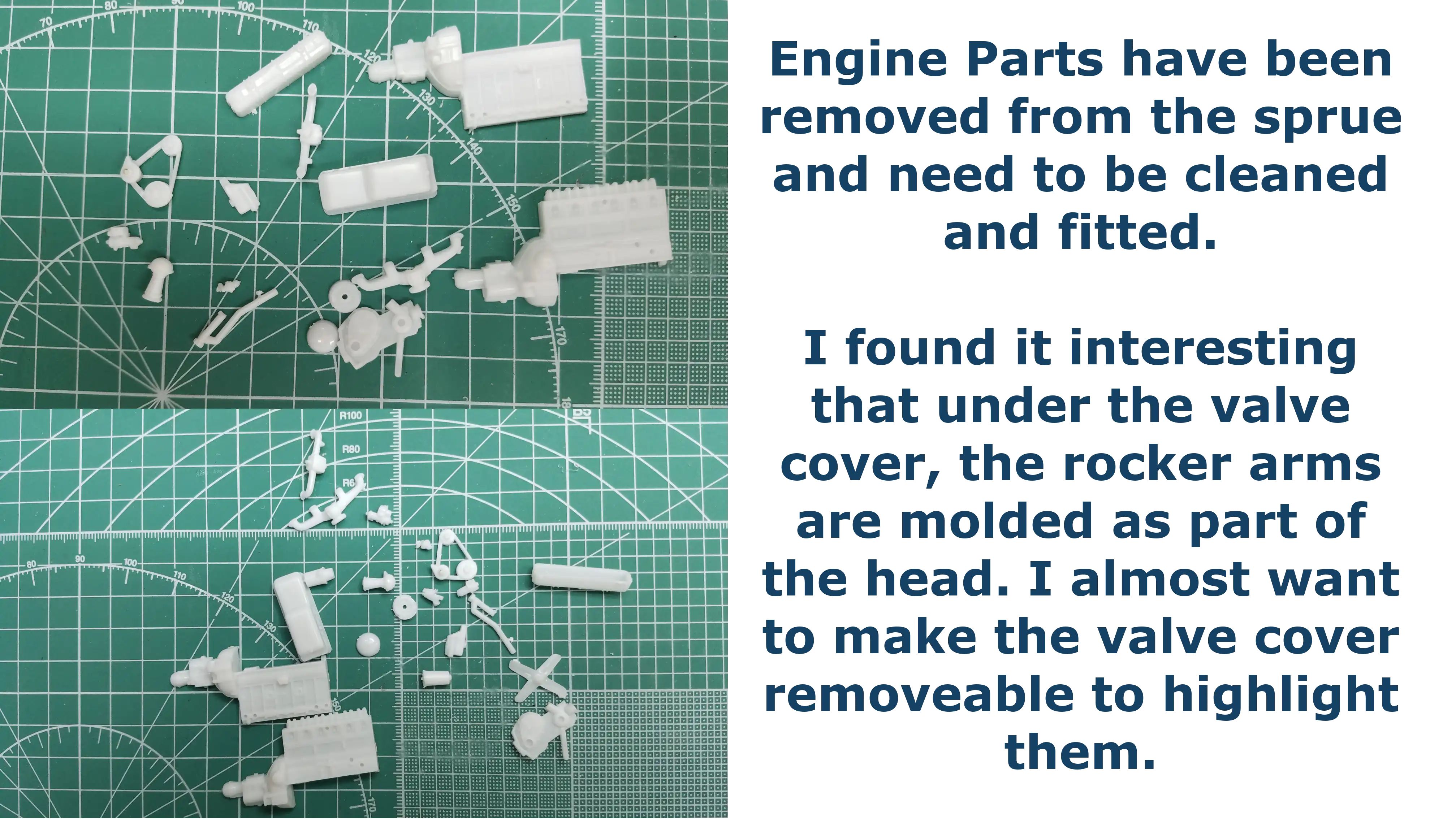 Engine parts removed from the sprues
 Valve rocker arms
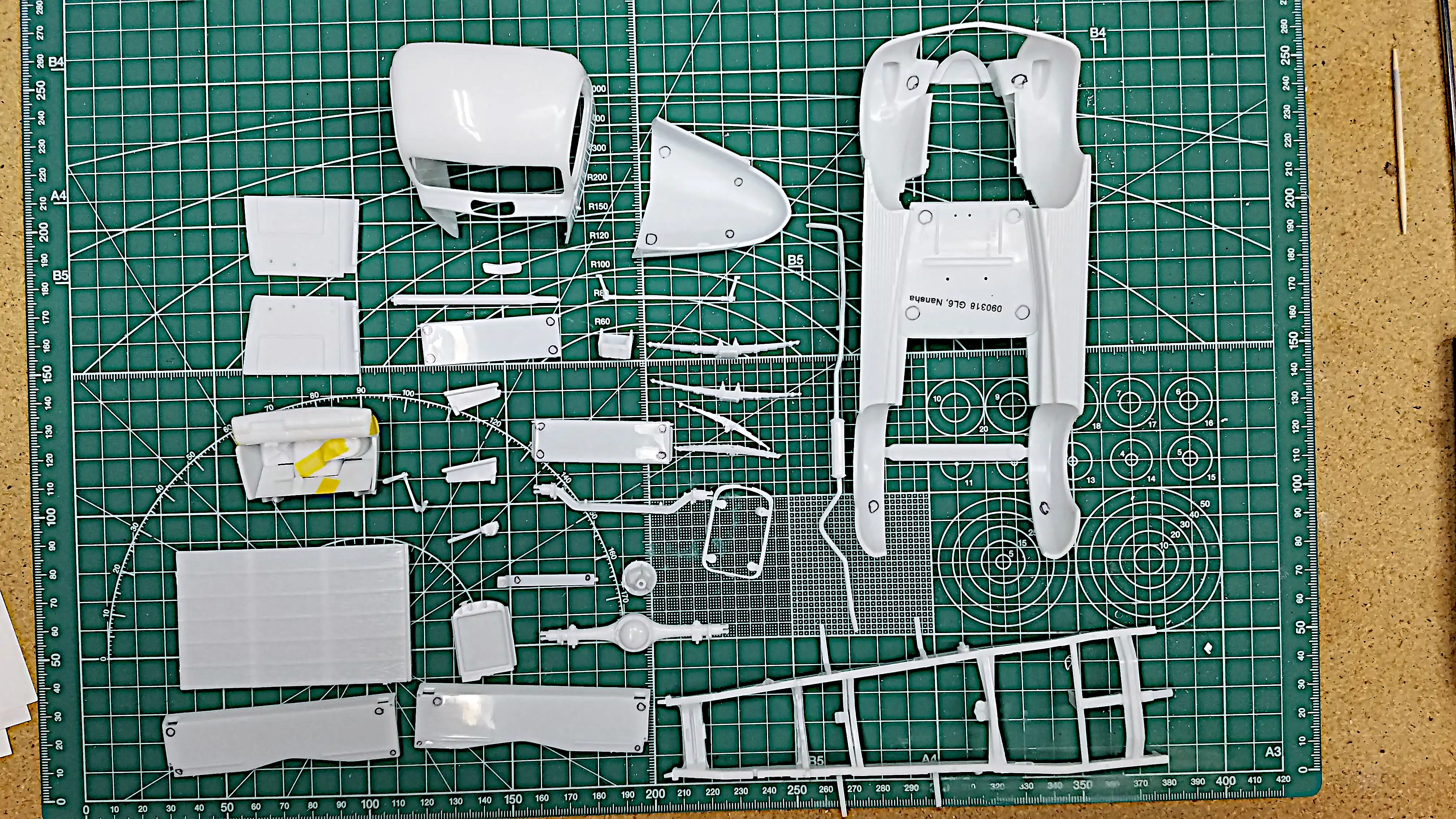 Most chassis parts are removed from the sprues
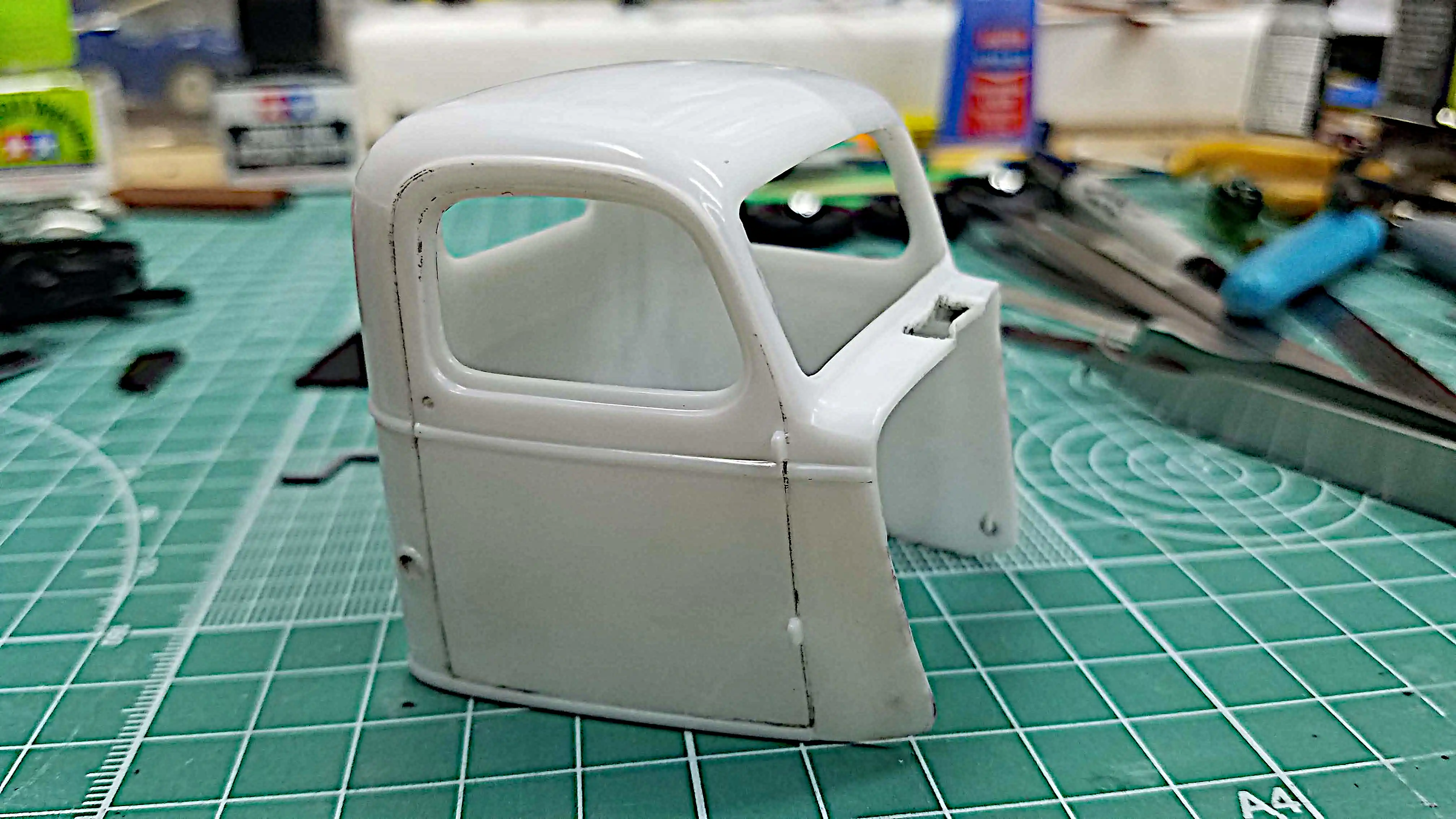
 Cowl vent is open
 Inject pin marks are marked for removal
 Parts from two kits being primed
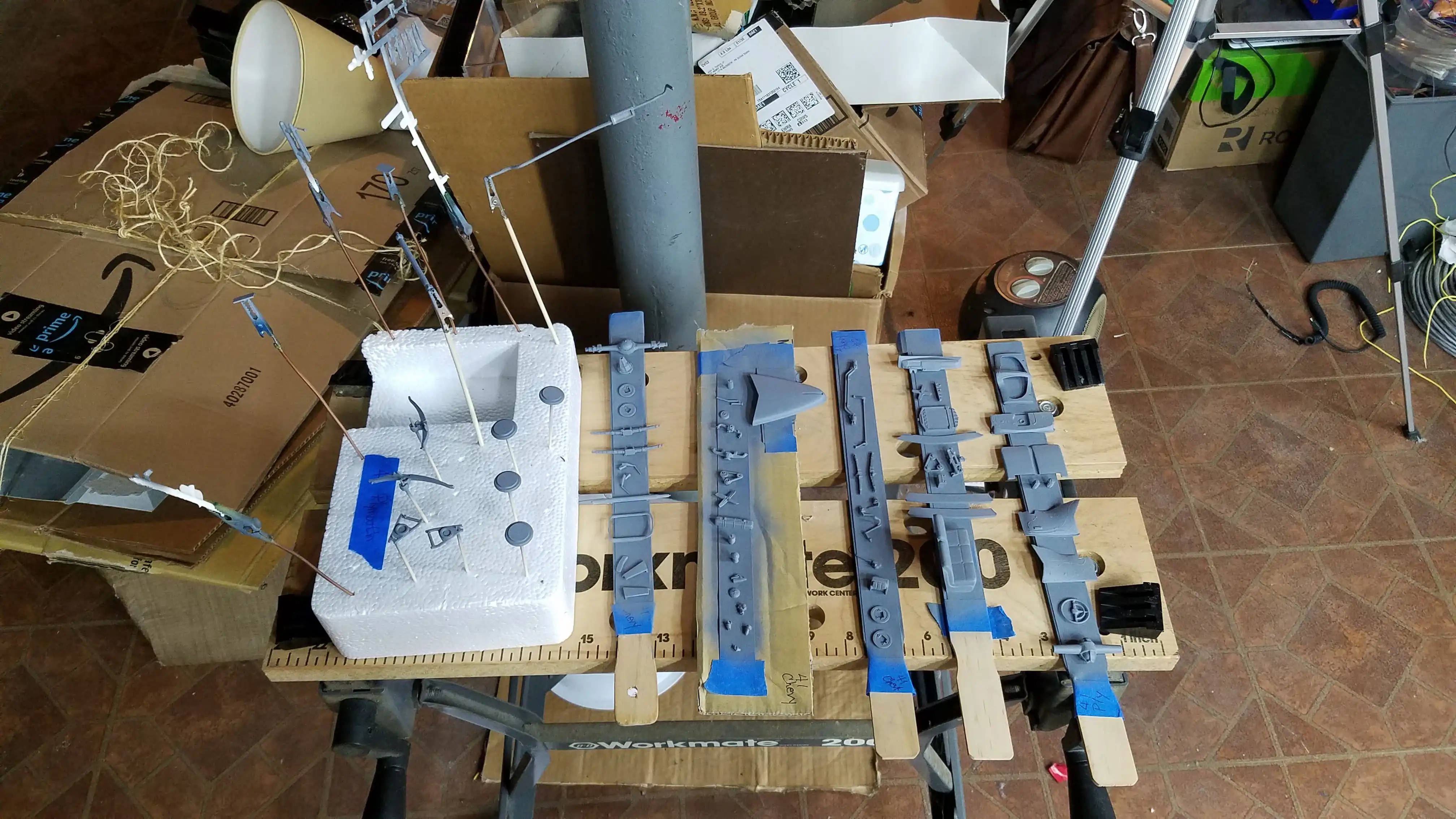 Parts from two kits being primed
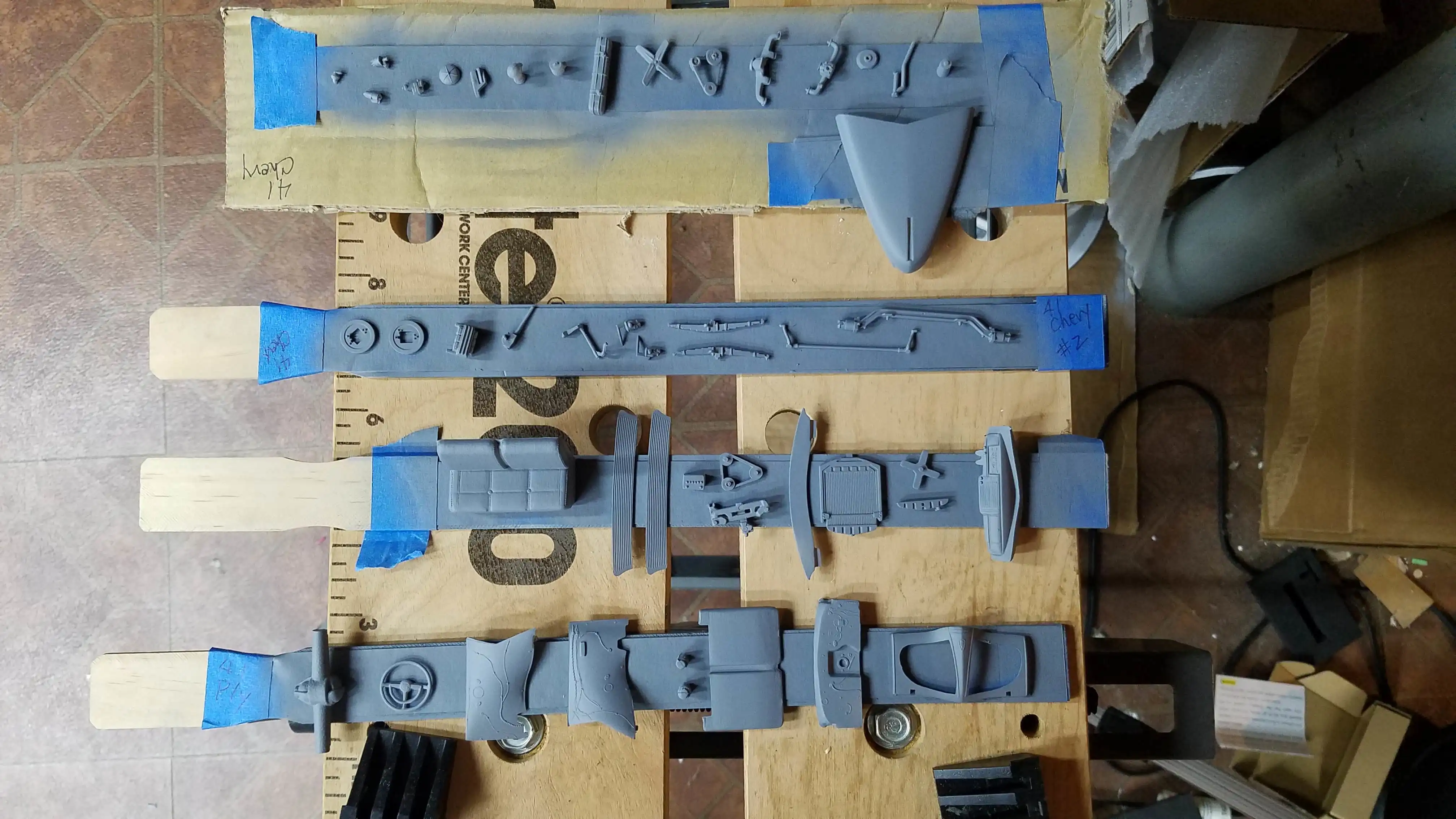 Parts from two kits being primed
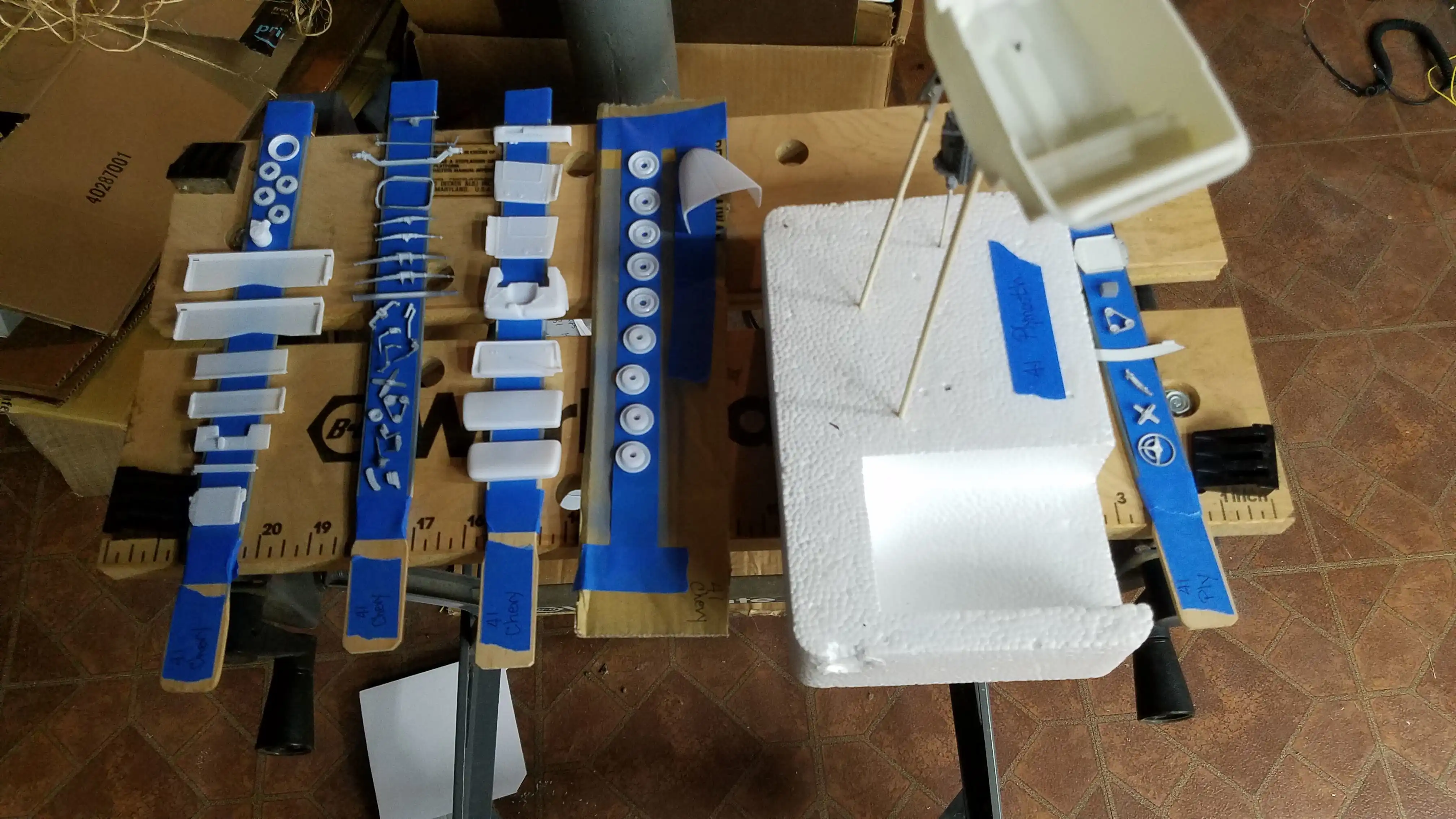 Parts from two kits being primed
 Parts from two kits being primed
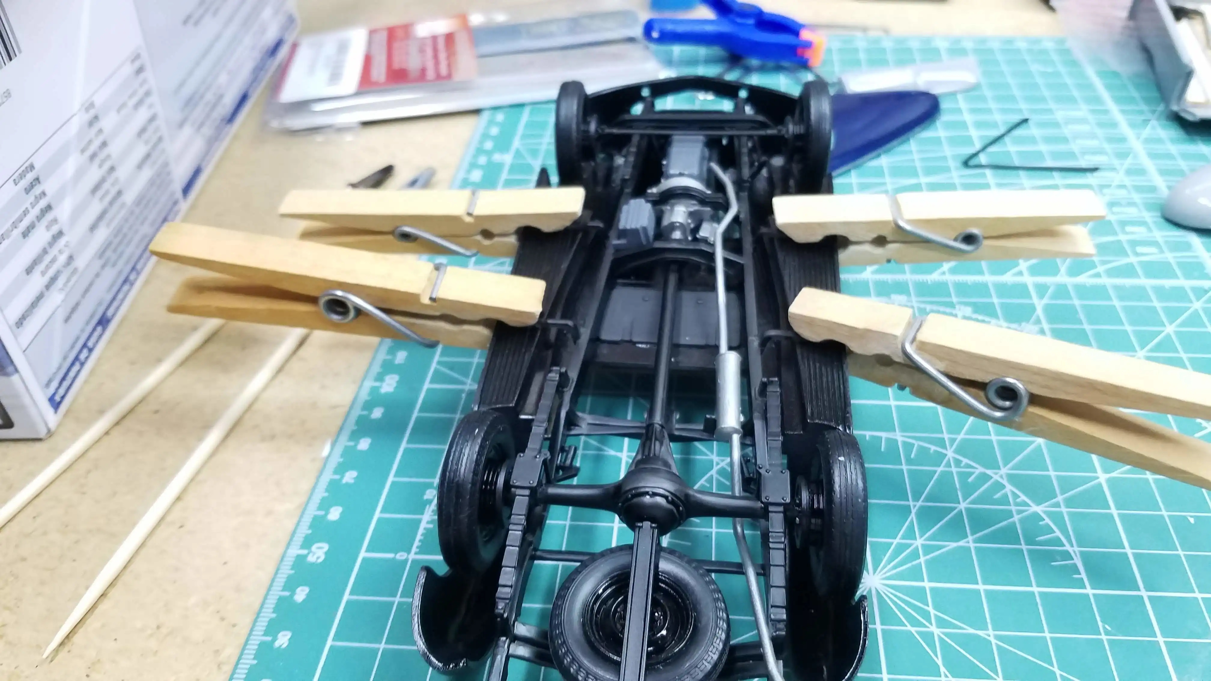
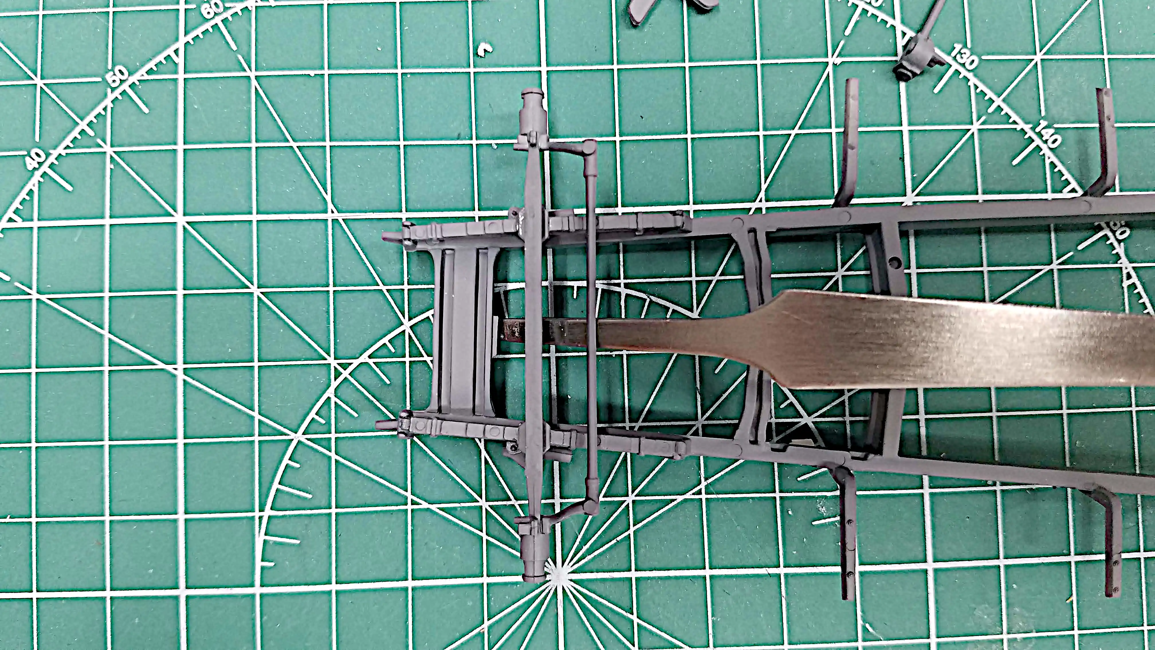 Started assembling the front suspension
 Started assembling the front suspension
 Steering box is installed
 Right front shock installed
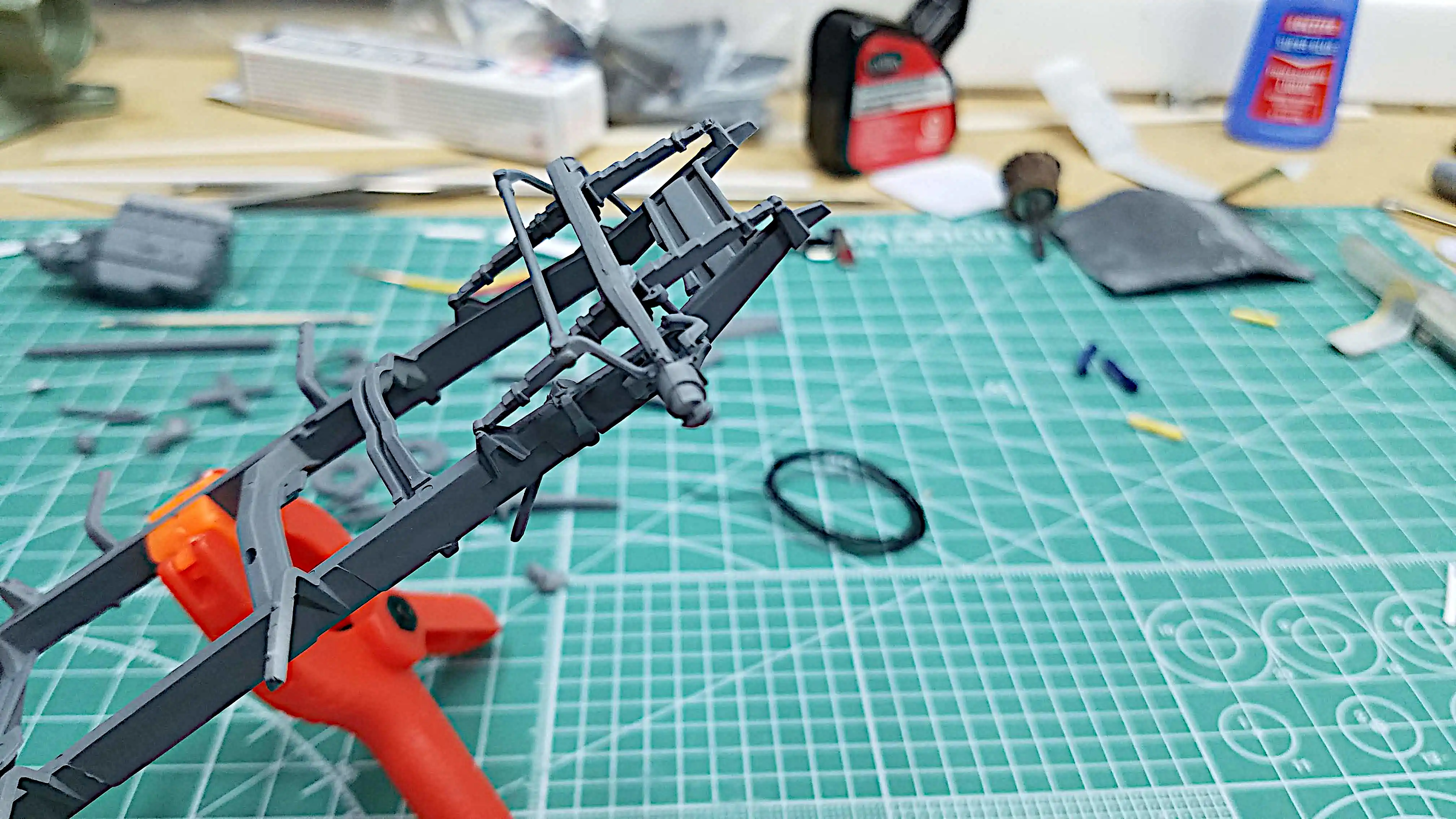
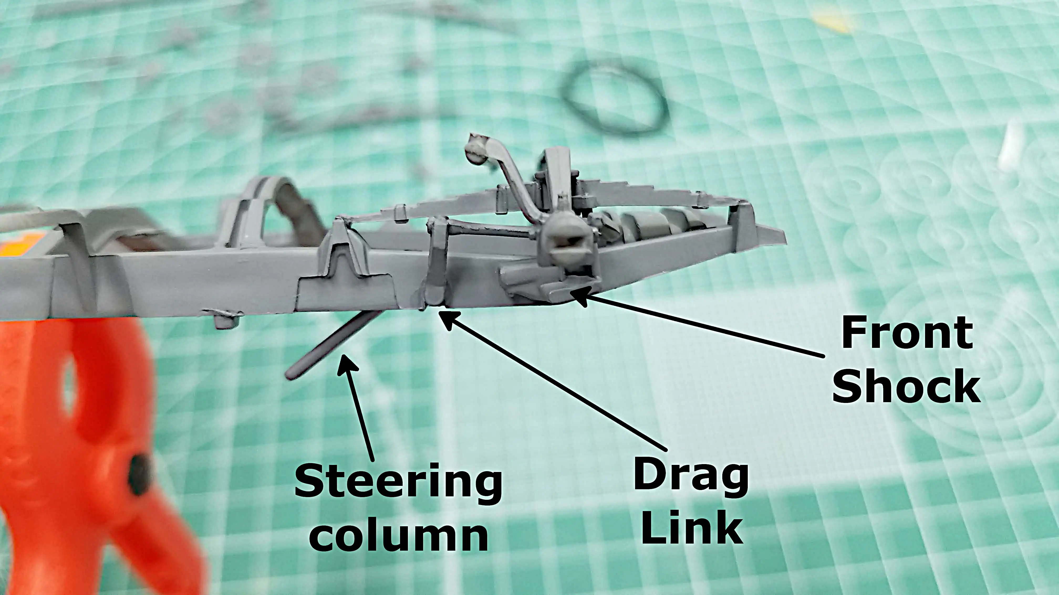 Front shocks, drag link and steering box installed
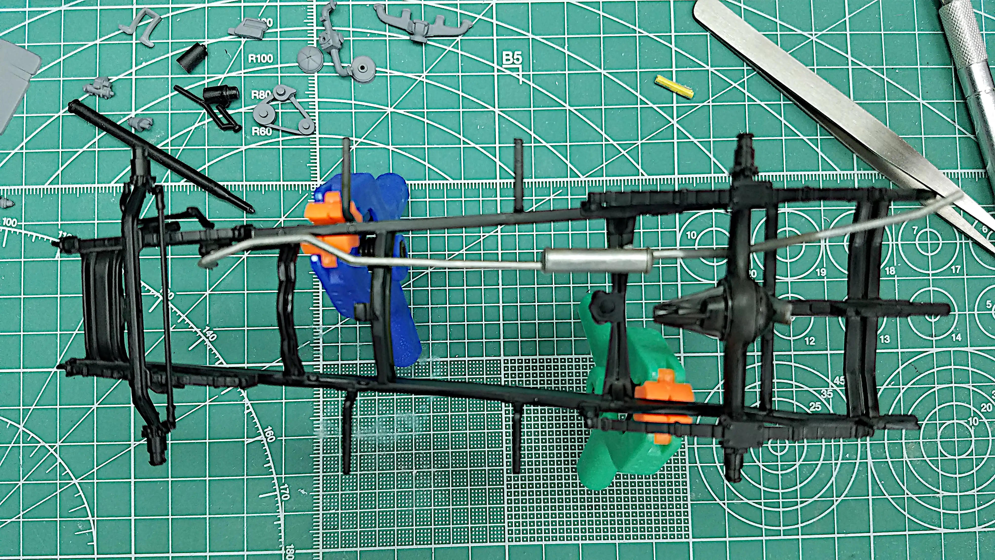 Frame painted, front suspenstion installed
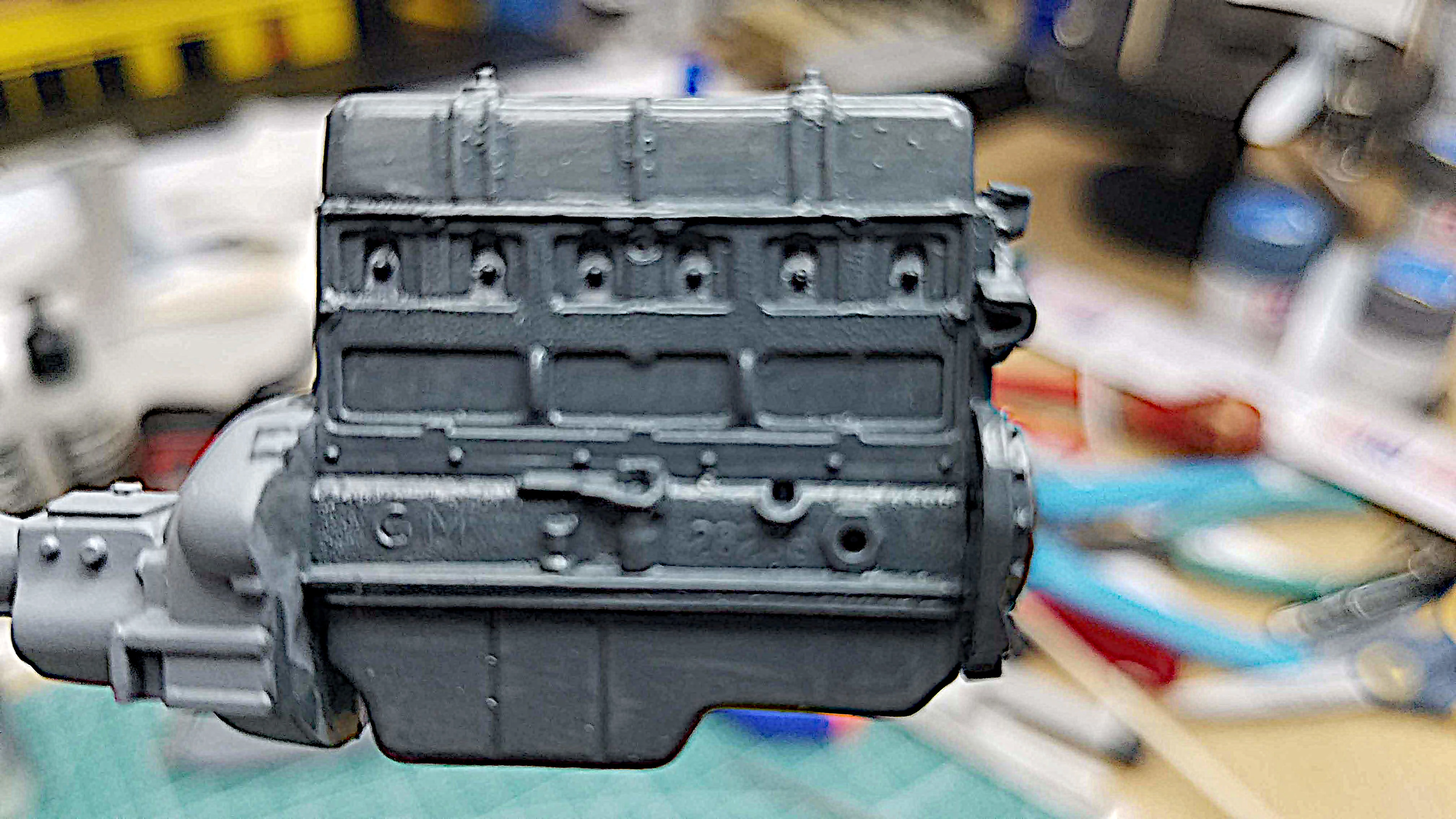 Engine painted
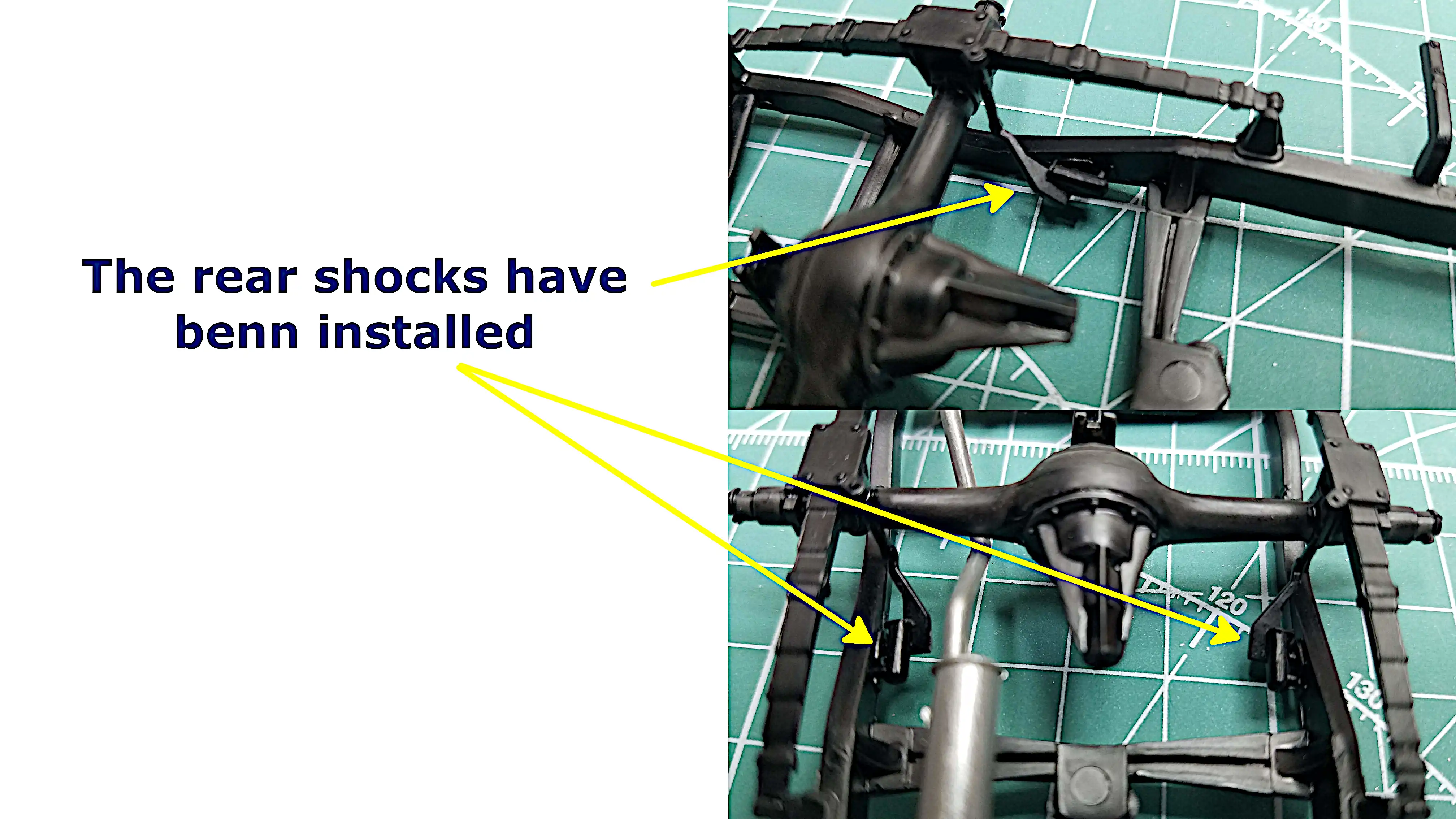 Rear shocks are installed
 Detailing the engine
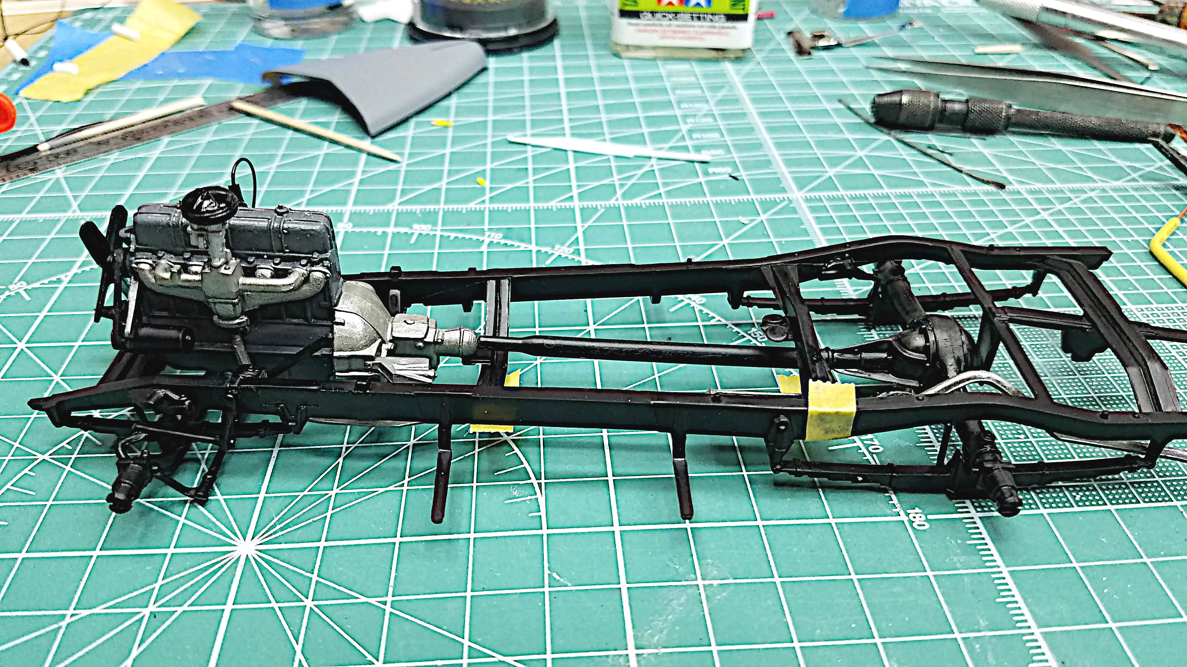 Mock up of engine, exhaust and drive shaft in the frame
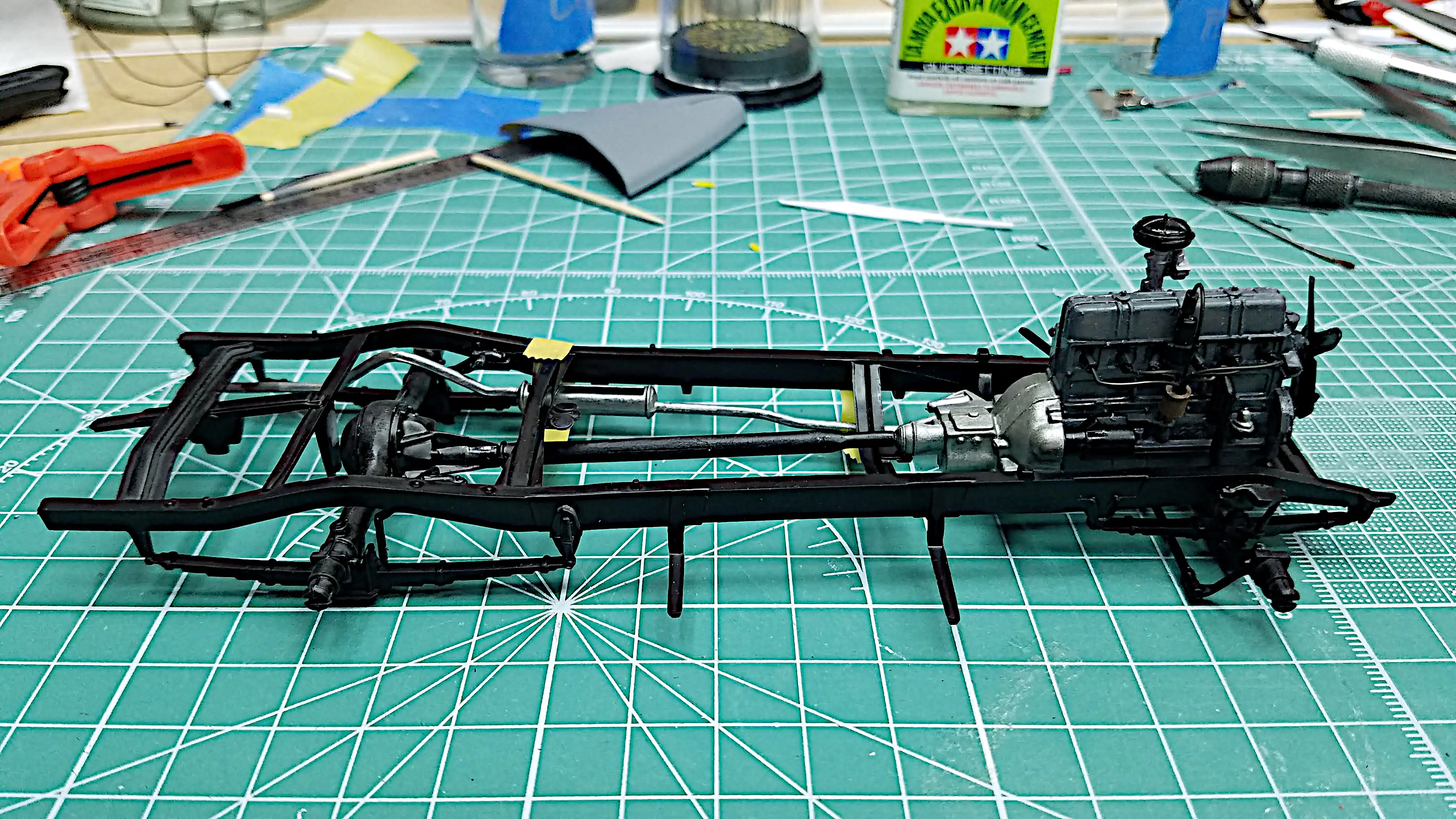 Mock up of engine, exhaust and drive shaft in the frame
 Close up of finished spark plug wiring
 Close up of finished spark plug wiring
 Fenders are painted
 Radiator and shroud are installed
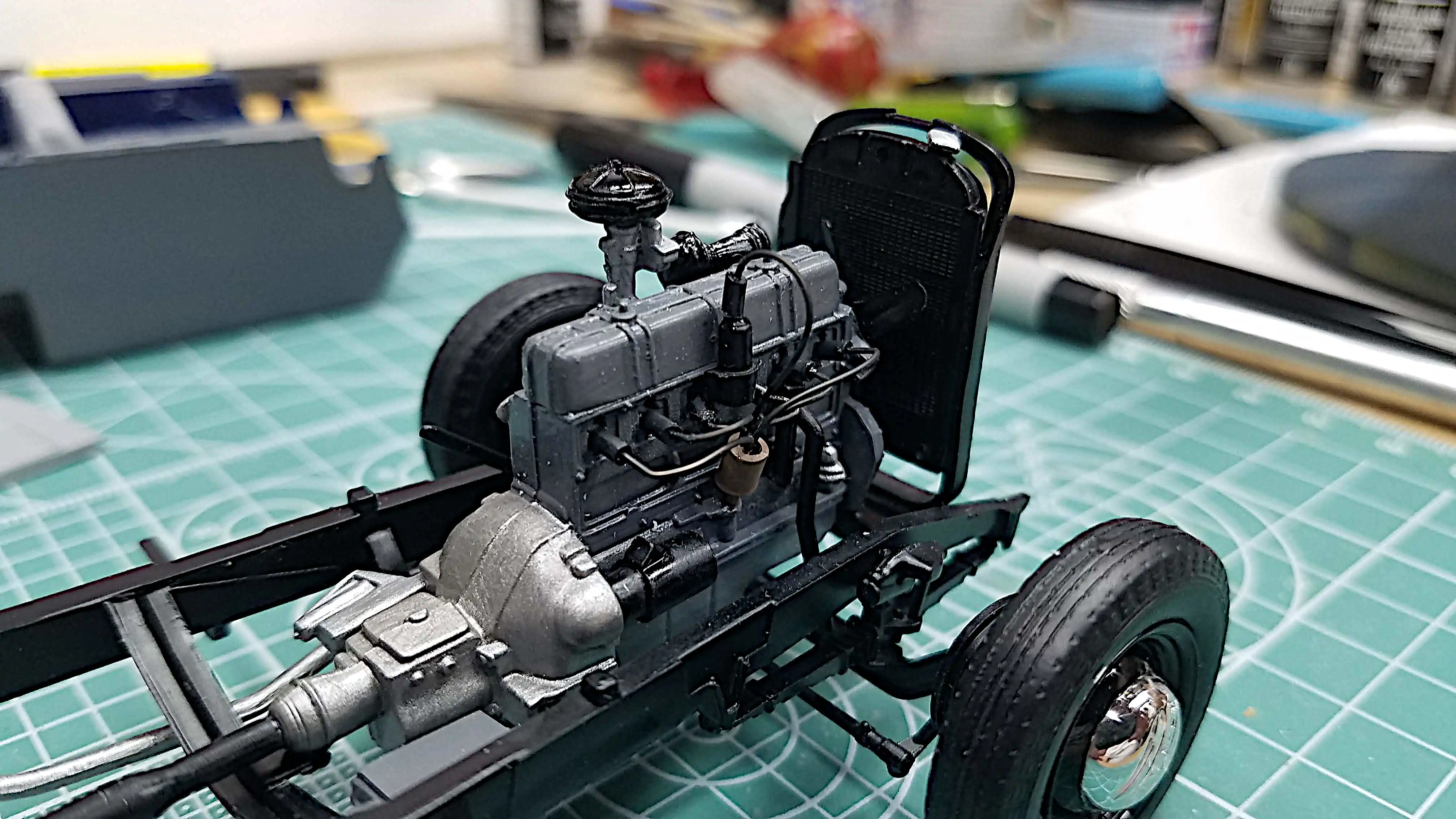 Radiator and shroud are installed
 Dry fitting lower body and fenders
 Upper and lower radiator hoses installed
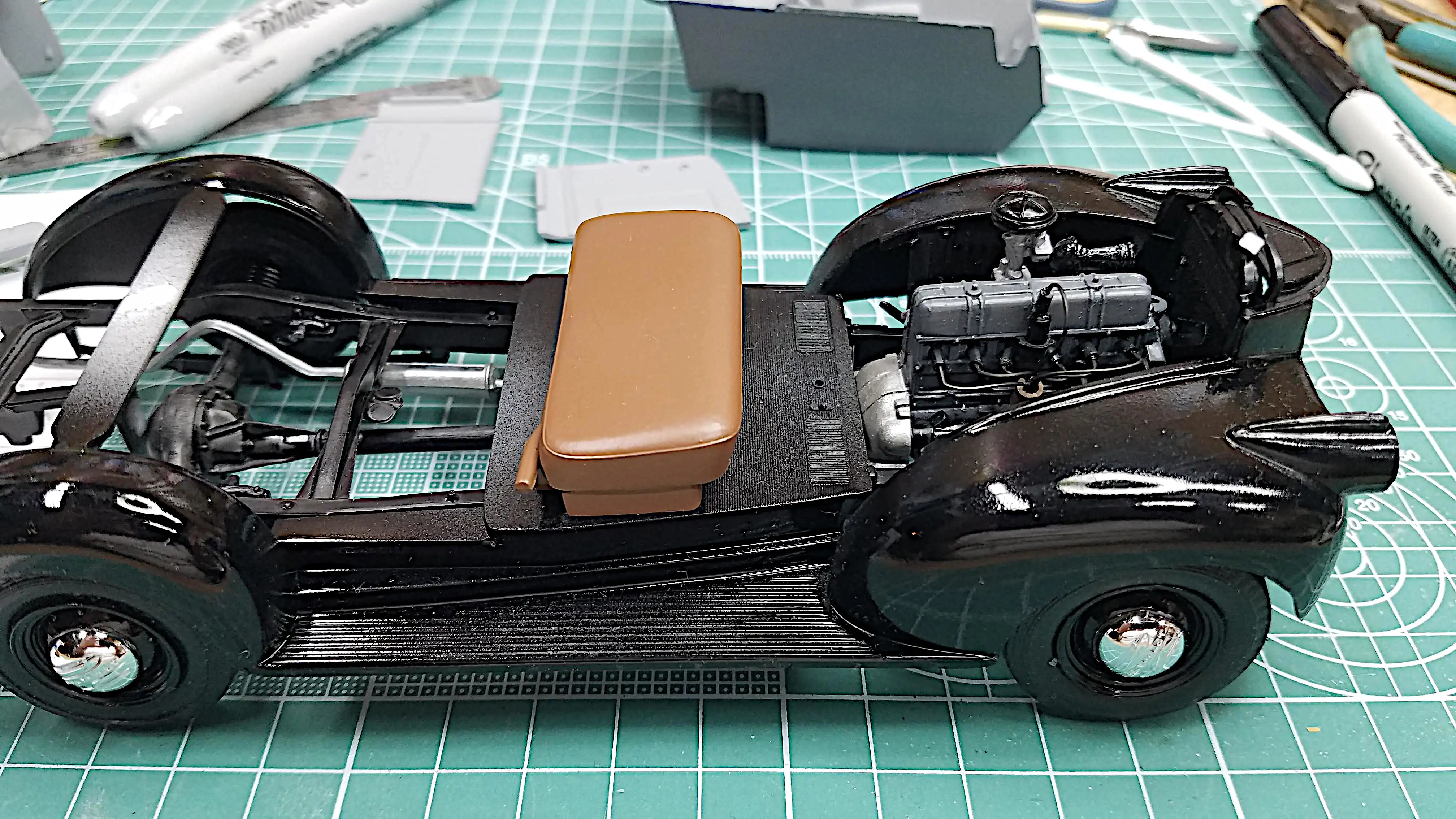
 Installed the floor board and pedals
 Stripped the paint off the body
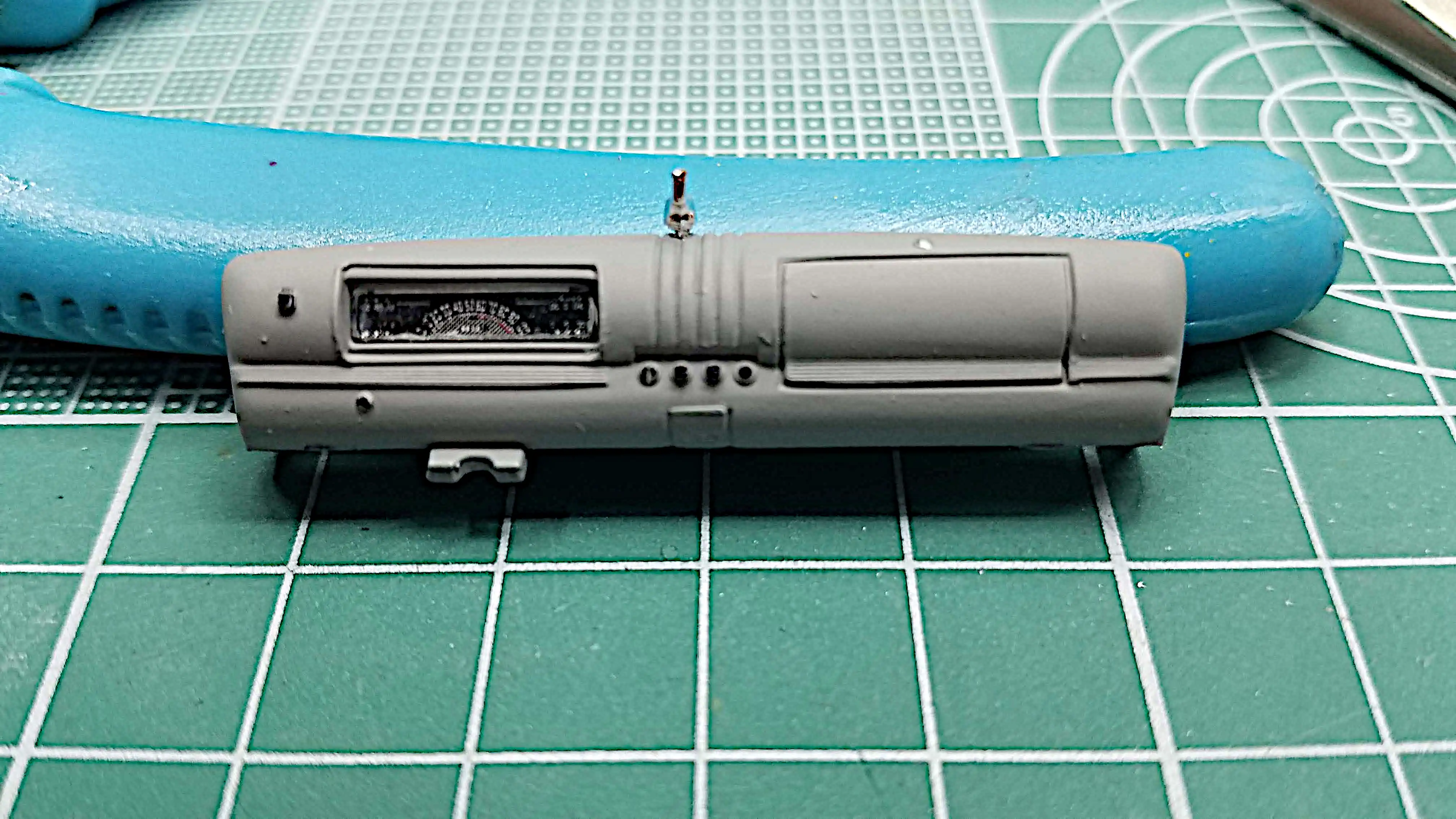 Dashboard is finished and ready to be installed
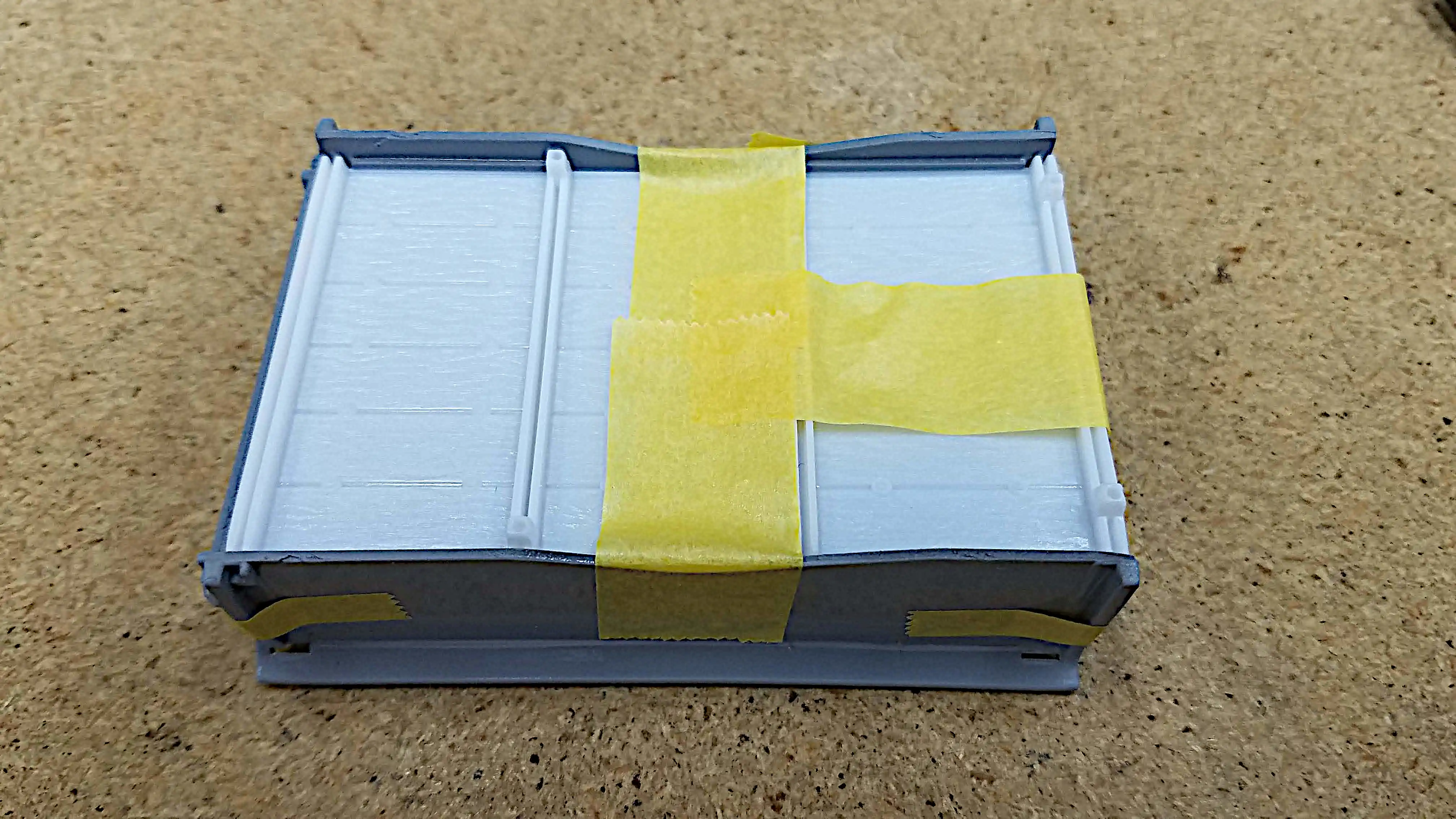 Assembling the truck bed
 Assembling the truck bed
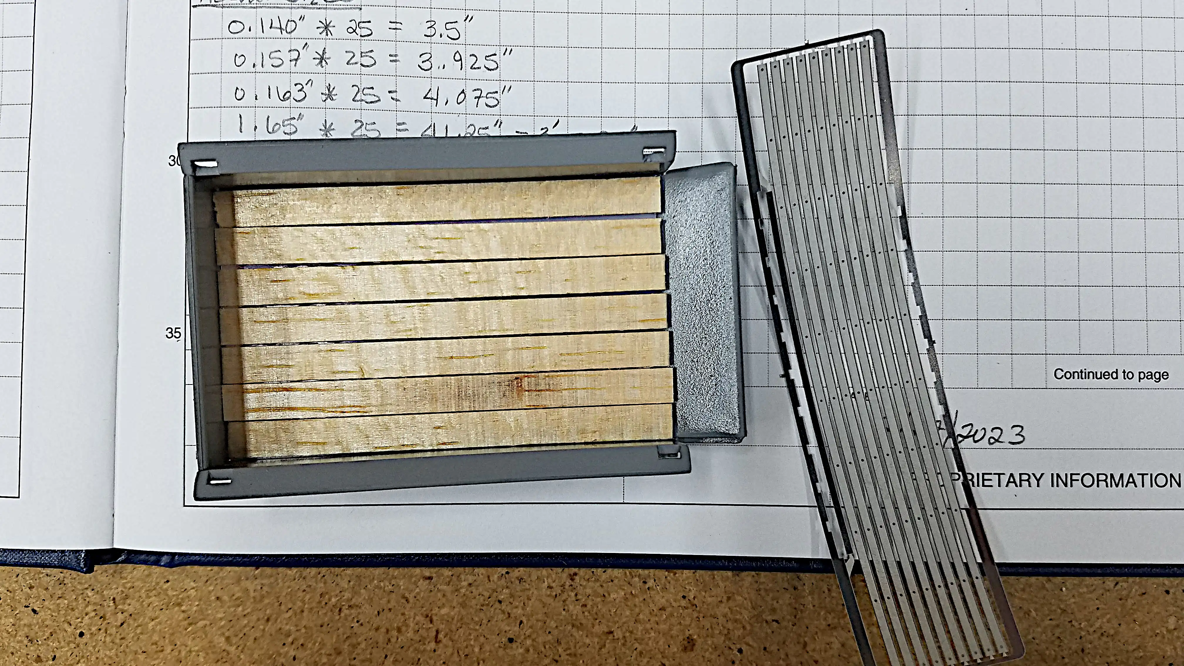 Using balsa wood for the truck bed
 Building the balsa wood bed
 Wooden bed build, but not installed
 Close up of the wood bed
 Testing glue on balsa wood
 Gluing the seam covers on the balsa wood of the bed
 Trimmed the seam covers
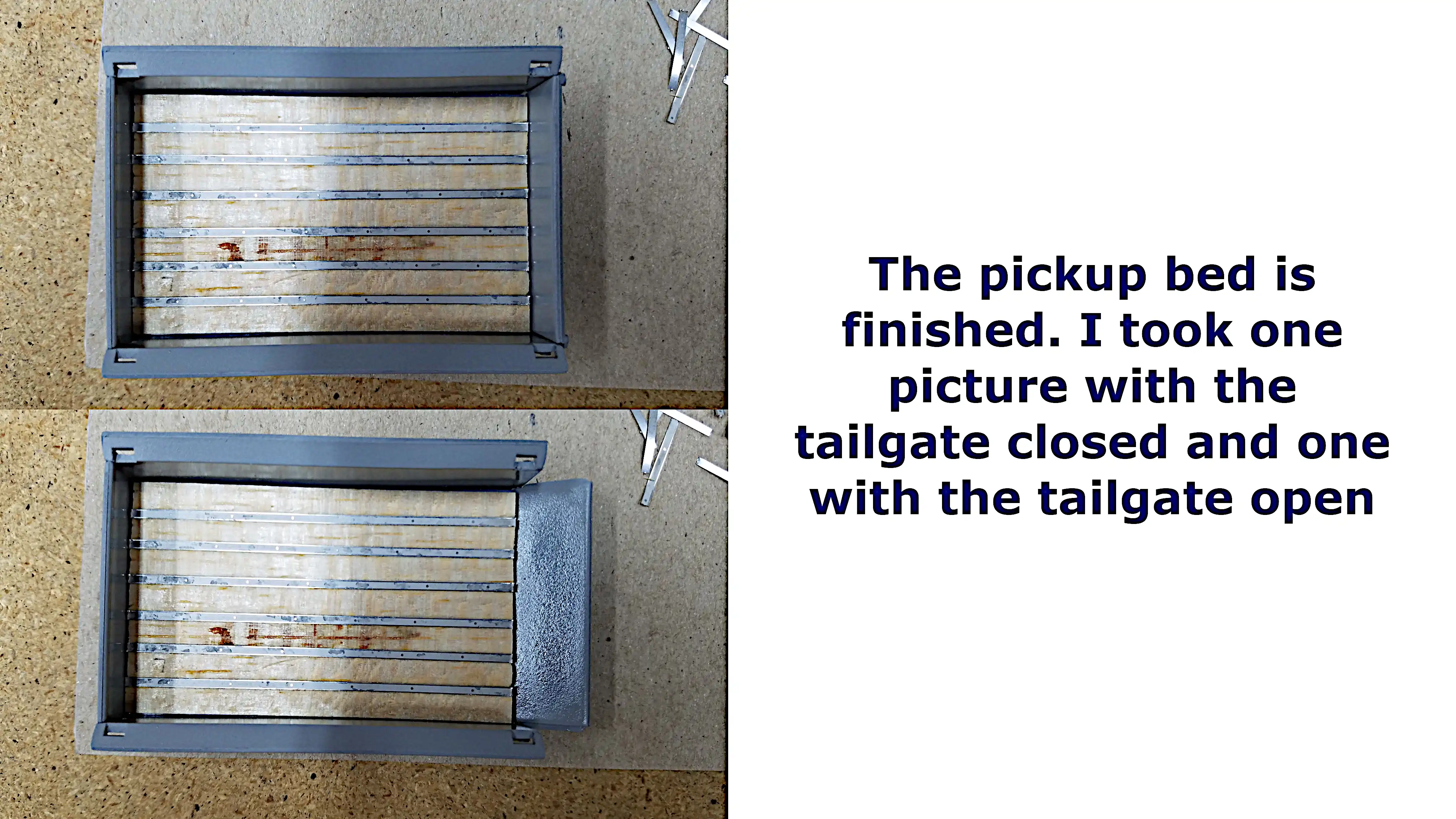 Pickup bed is finished
 Working on the truck frame
 How the rear bumper mounts were aligned
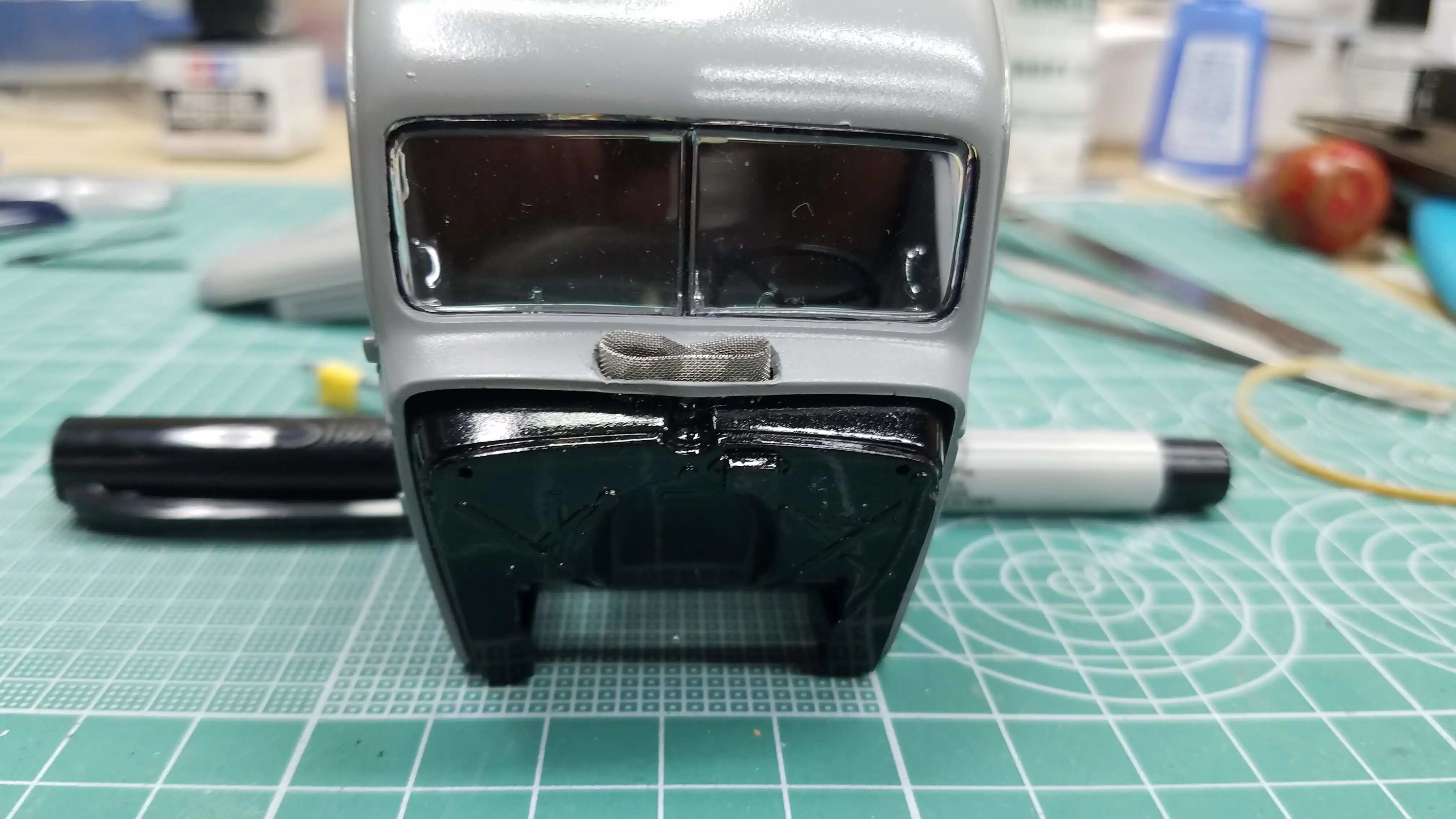 Starting to build the cowl screen
 Building the cowl vent
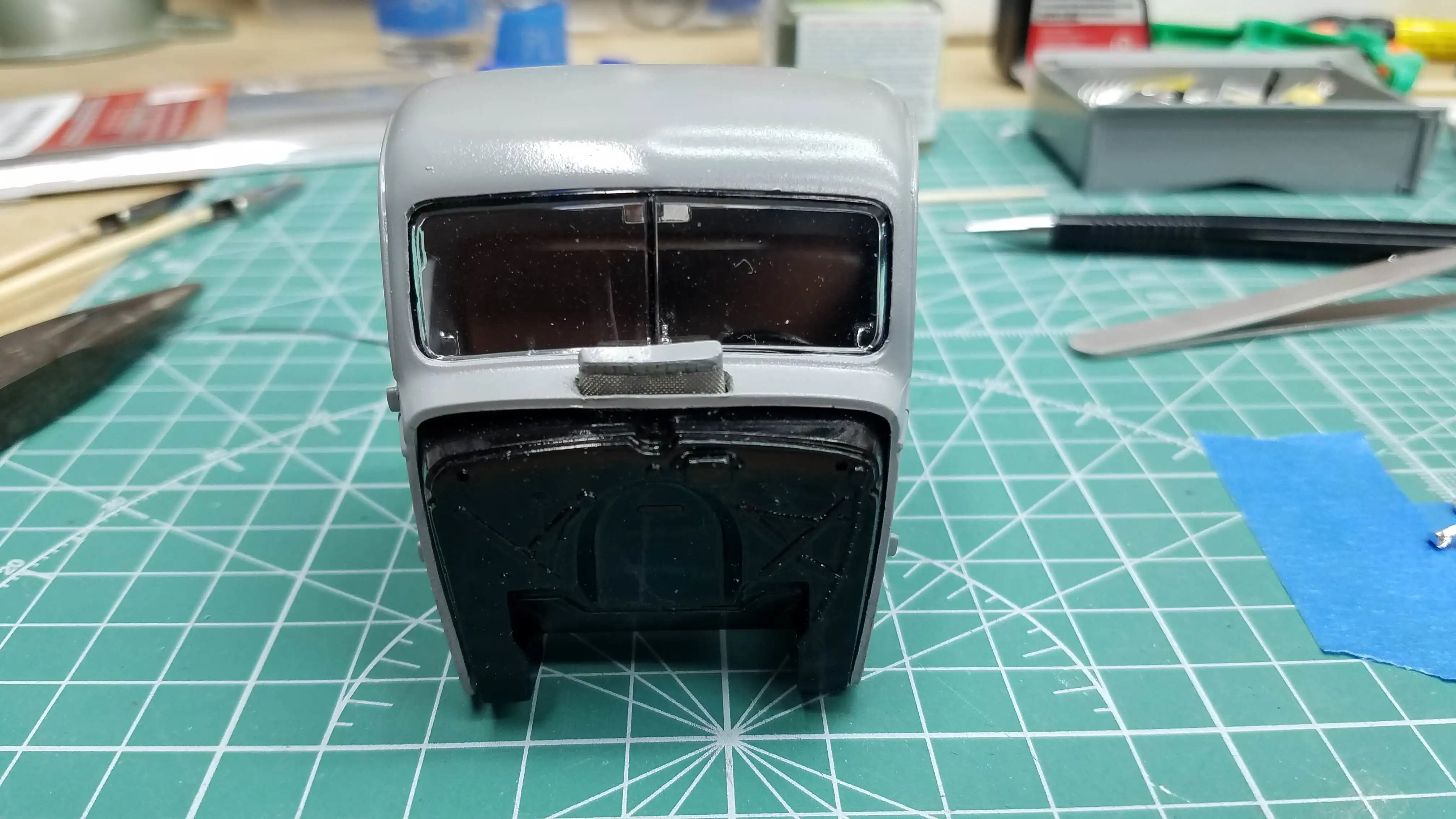 Cowl vent is finished
 Installing the frame to the fenders
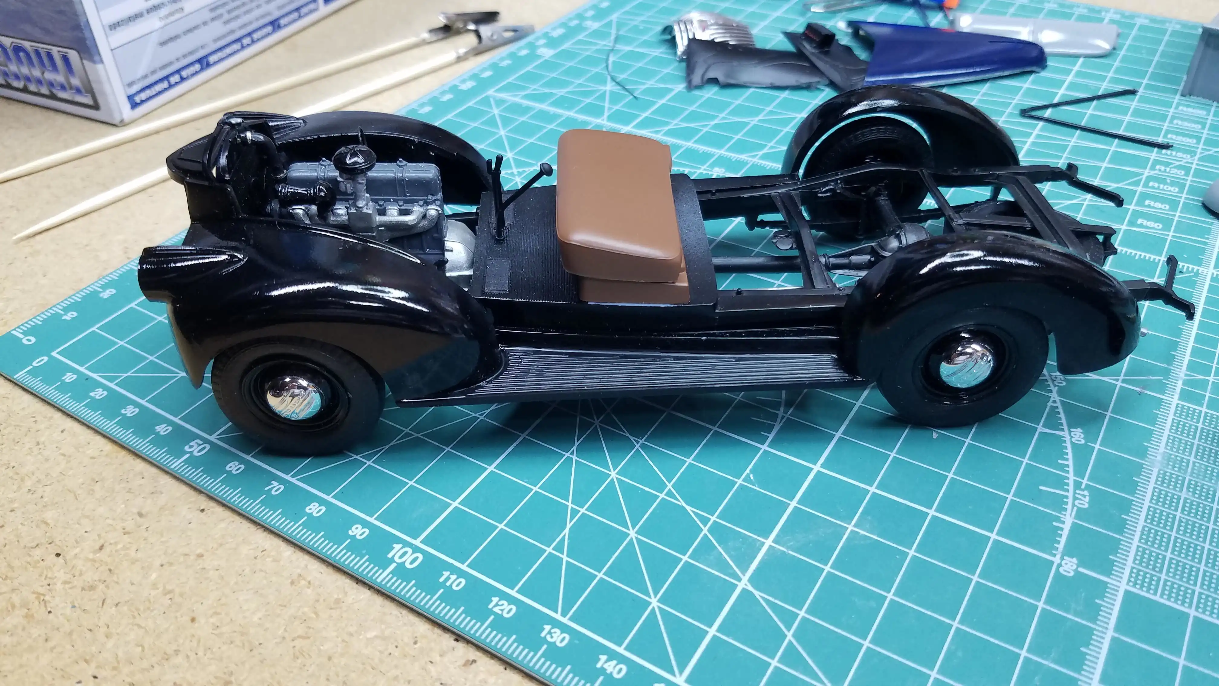 Chassis and body bottom ready for the cab and bed
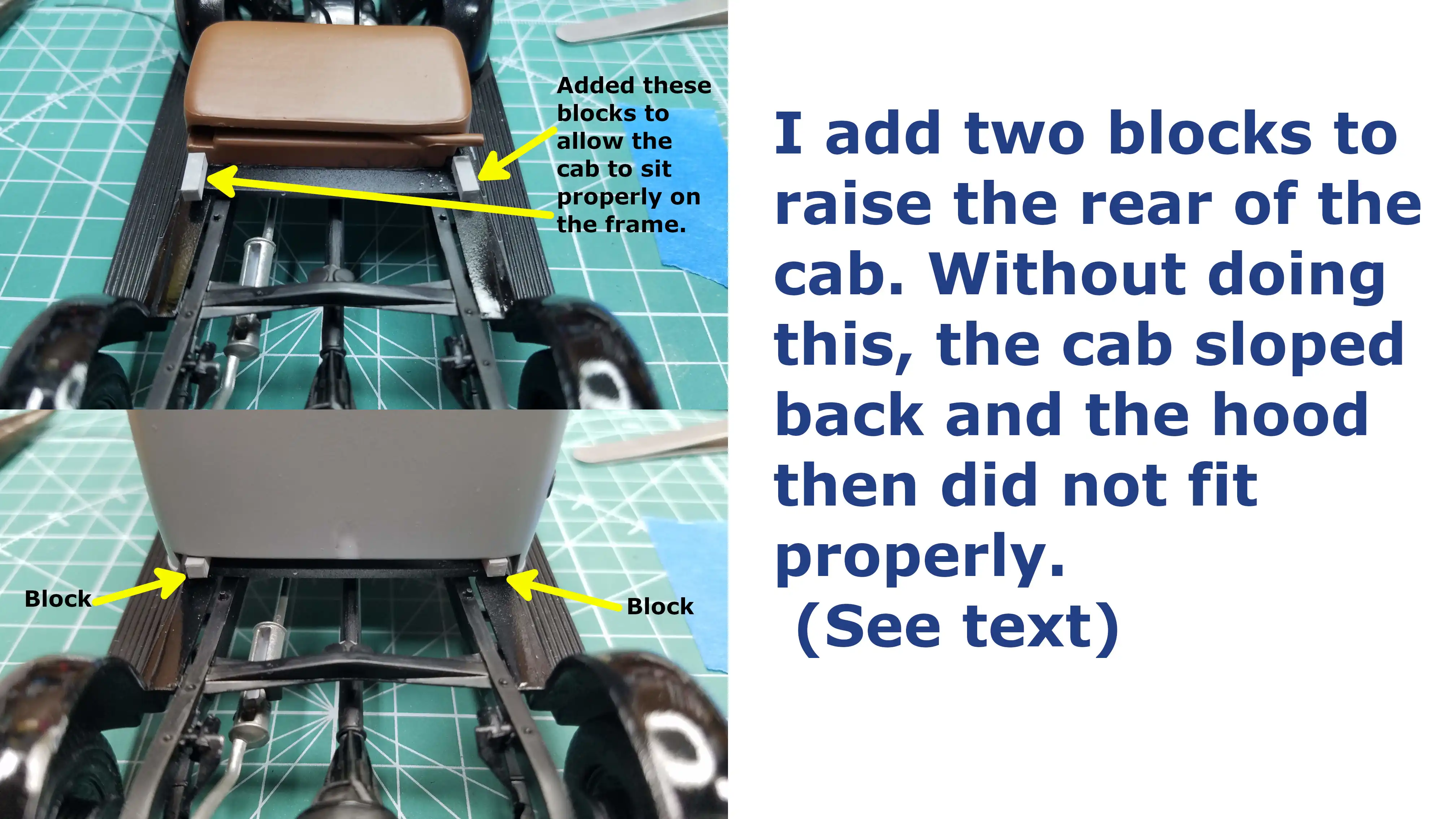 Modification to make the cab fit correctly
 Cab is put in place
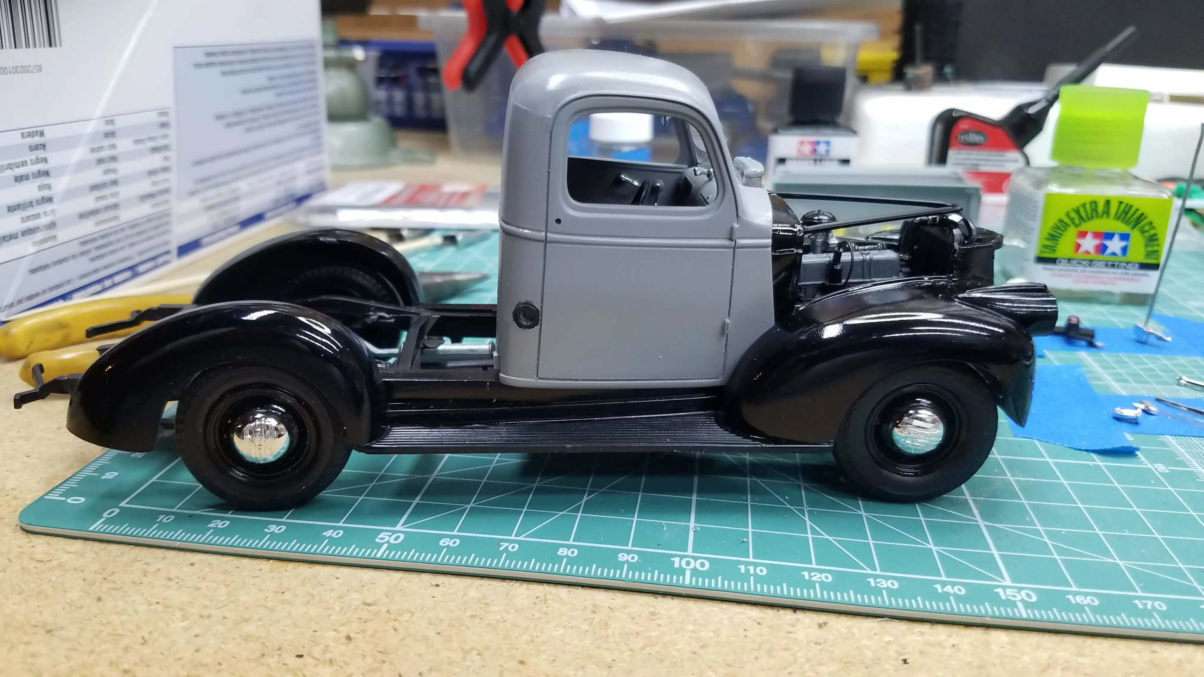
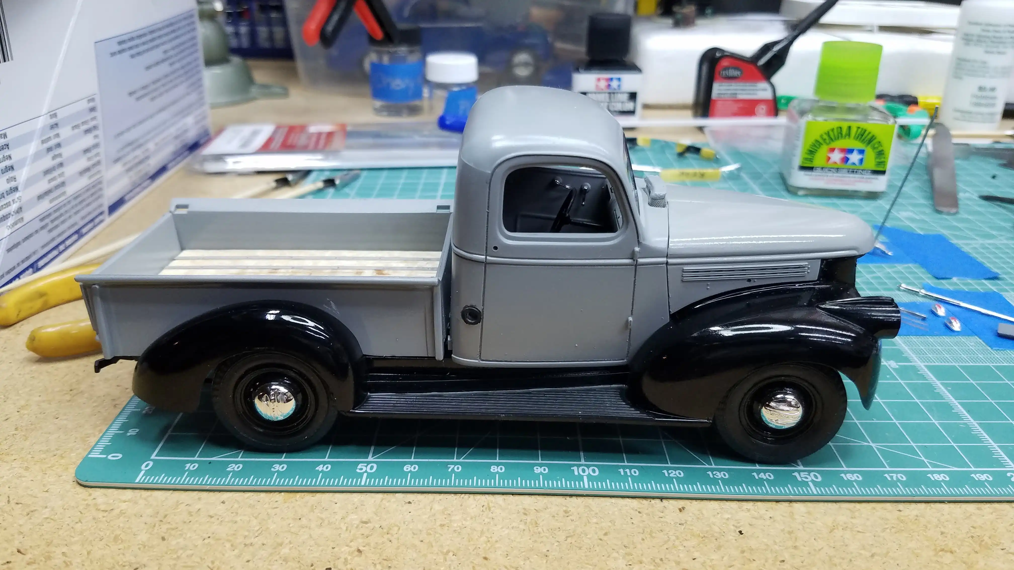 Cab, bed and hood are in place
 Cab, bed and hood are in place
 Grill and front bumper installed
 I make my own license plates
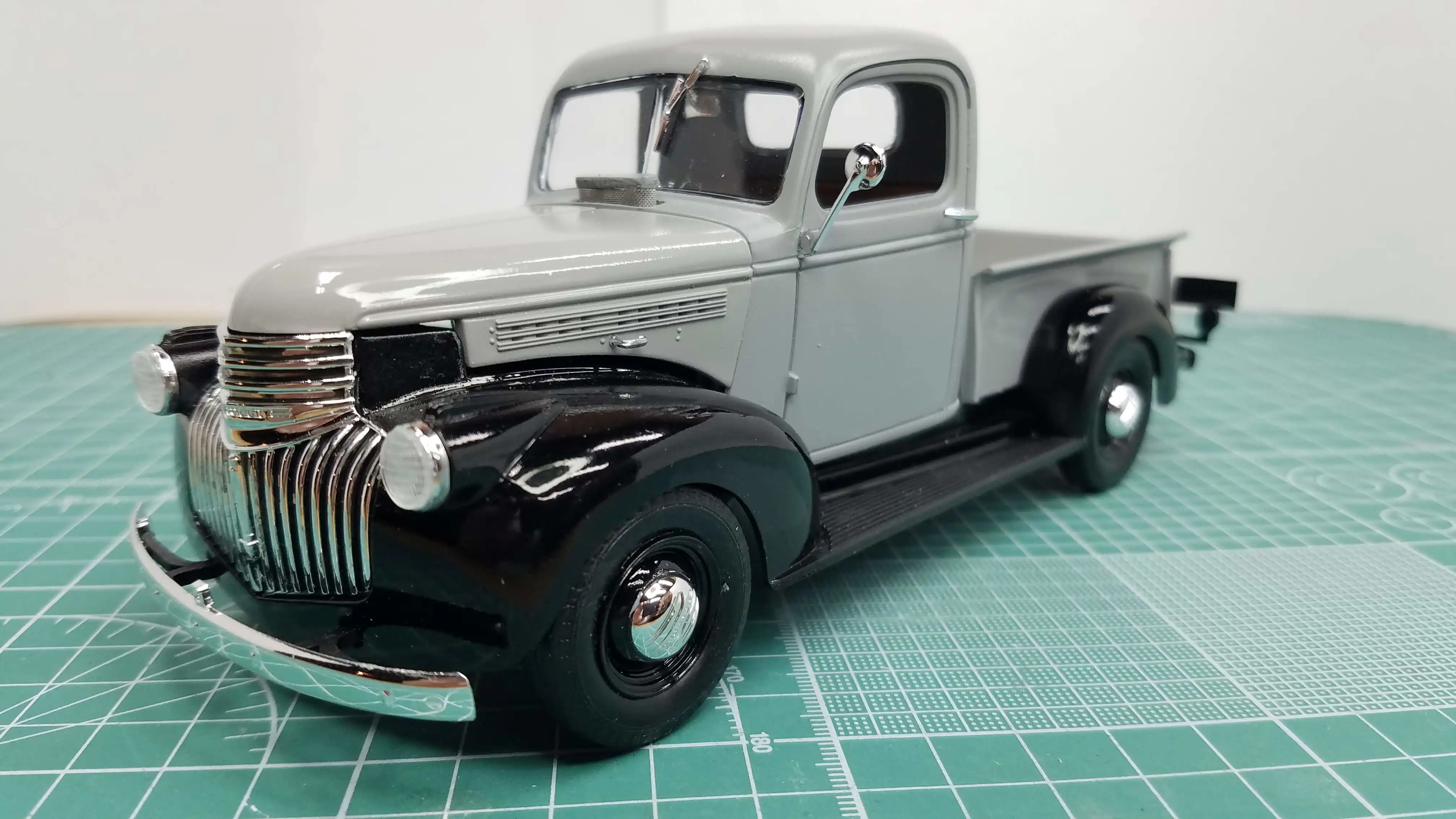
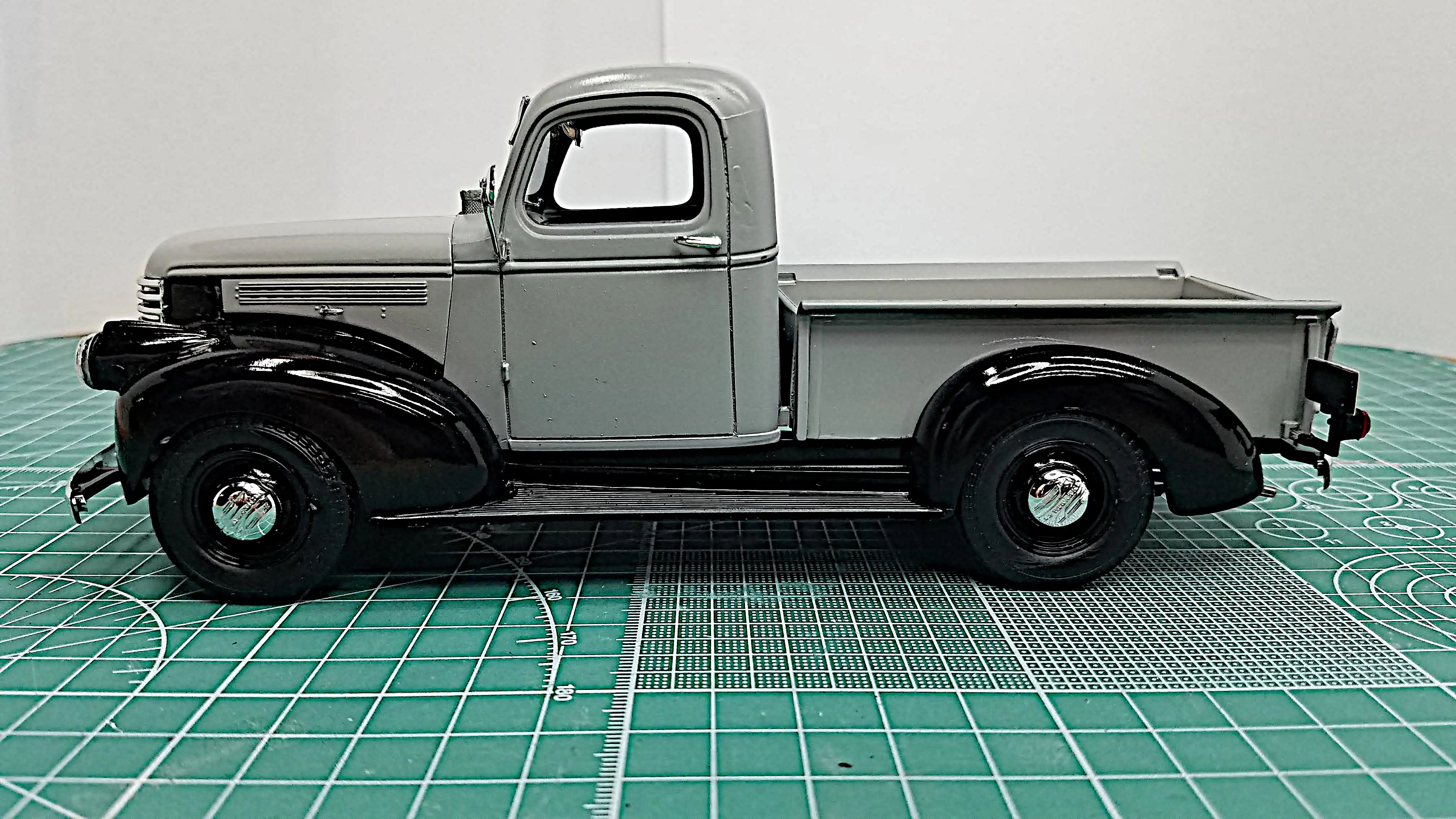
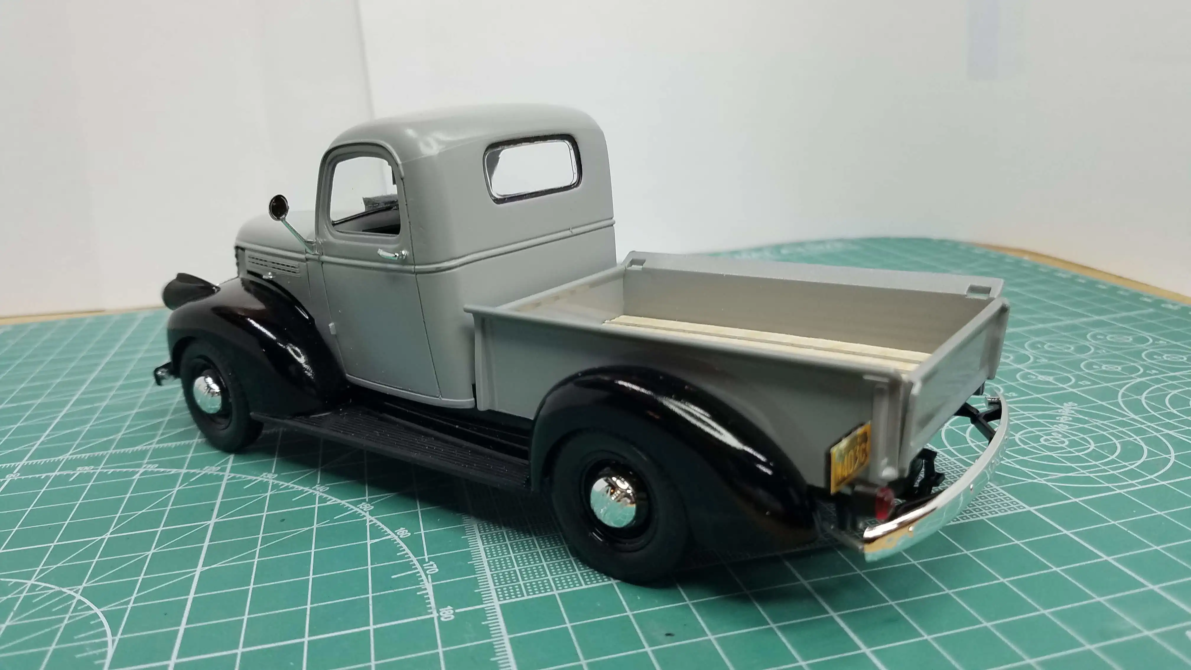
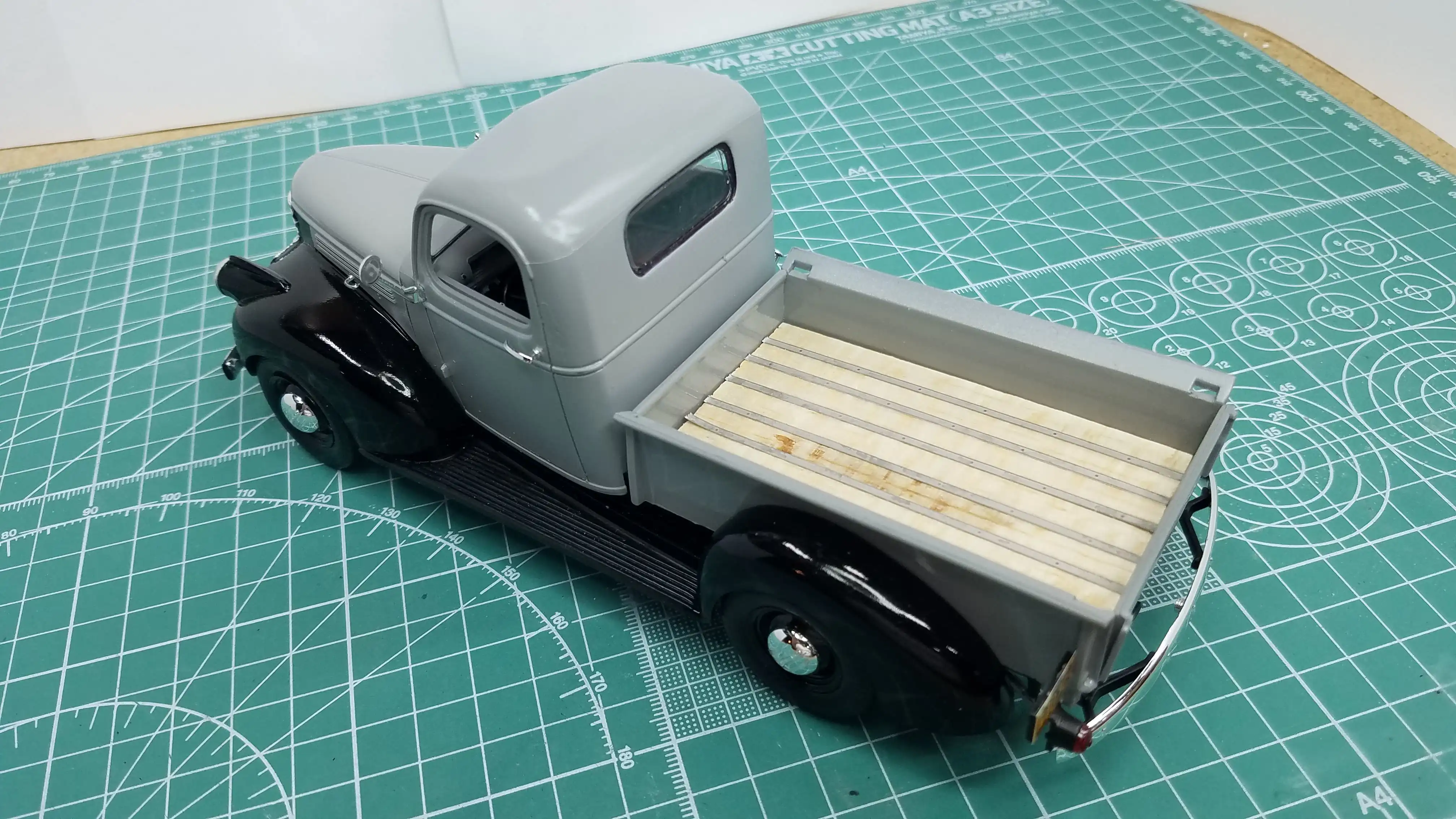
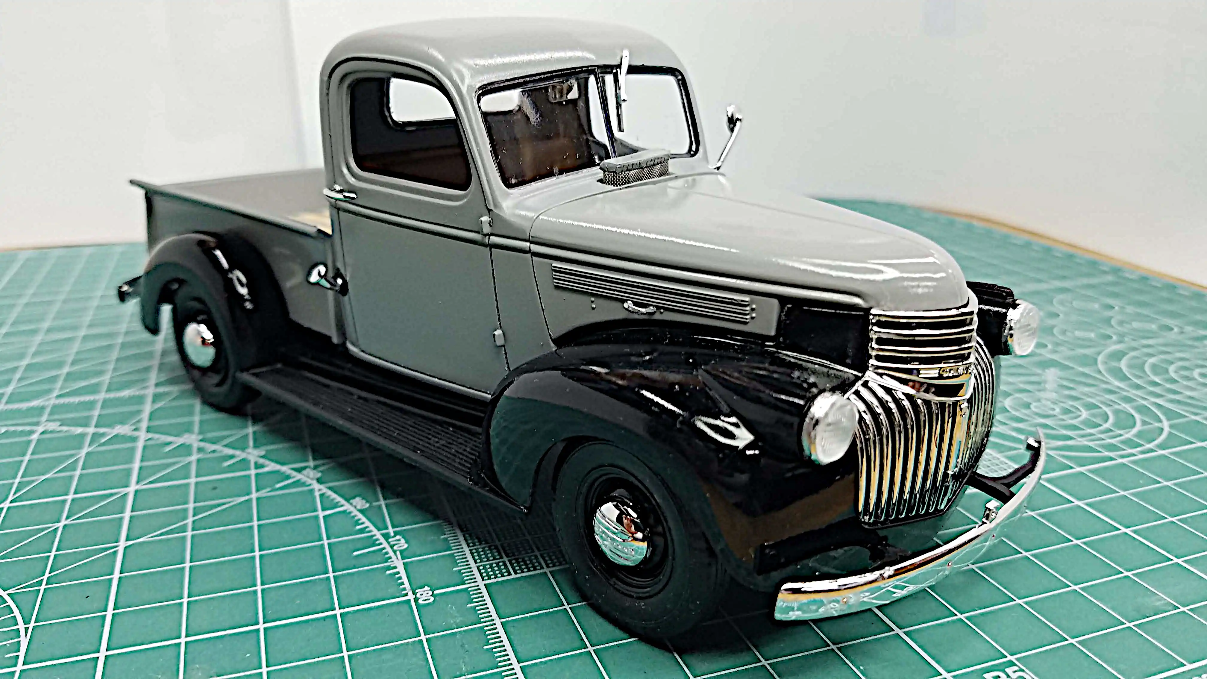 The '41 Chevy Pickup is finished
 The '41 Chevy Pickup is finished
 The '41 Chevy Pickup is finished
 The '41 Chevy Pickup is finished
 The '41 Chevy Pickup is finished
 The '41 Chevy Pickup is finished
 The '41 Chevy Pickup is finished
 The '41 Chevy Pickup is finished
 The '41 Chevy Pickup is finished
 The '41 Chevy Pickup is finished
 The '41 Chevy Pickup is finished
 The '41 Chevy Pickup is finished
 The '41 Chevy Pickup is finished
 The '41 Chevy Pickup is finished
 The '41 Chevy Pickup is finished
 The '41 Chevy Pickup is finished
 The '41 Chevy Pickup is finished

