
Opening
Click/tap photo to enlarge
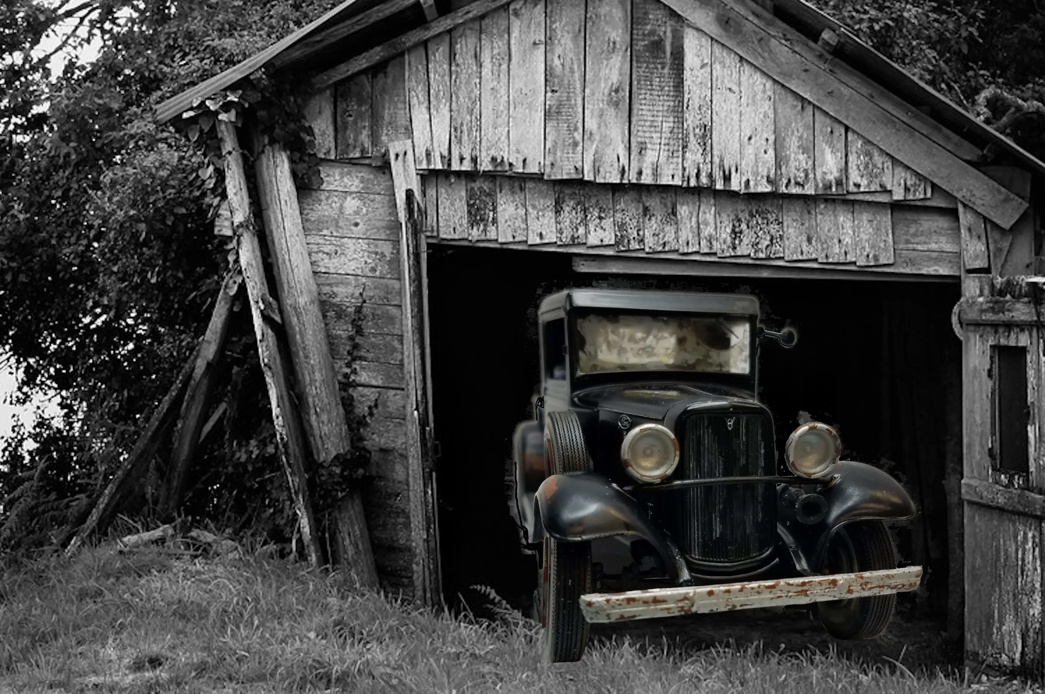
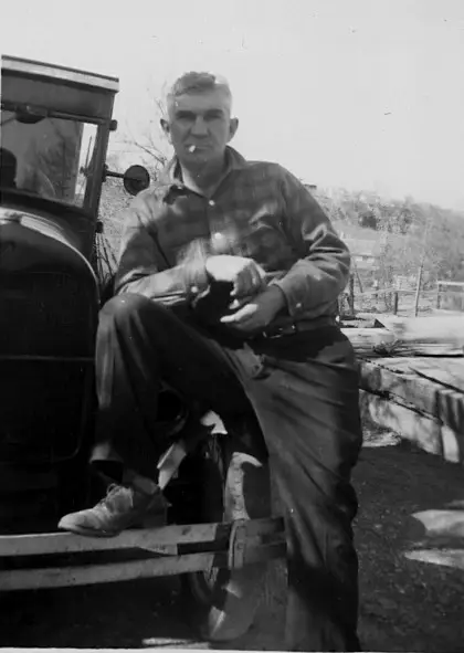 My Grandfather and his truck
This is my granfather with the truck I remember and was inspiration for why I decided to build this 1934 Ford Pickup.
I was only about 6 or 7 years old so my memory is vague; however, I do remember going to a junk yard with my dad and getting a headlight for this truck. I then remember watching and trying to help my dad replace the broken one on my grandfathers (my dad's father-inlaw), truck. My dad was amazing! He had so much patience with me and always spent time with me, letting me help him with anything. When I got older I used to tease him. I'd say, pop... you taught me everything I know. Then I went to school and learned the right way. It was all in fun. He was willing to try anything and taught me the same. His philosophy was, a man built that, that means I can do it to.
I'm fairly sure my granfathers truck was not a '34 Ford, but the AMT '34 was the closest model I could find.
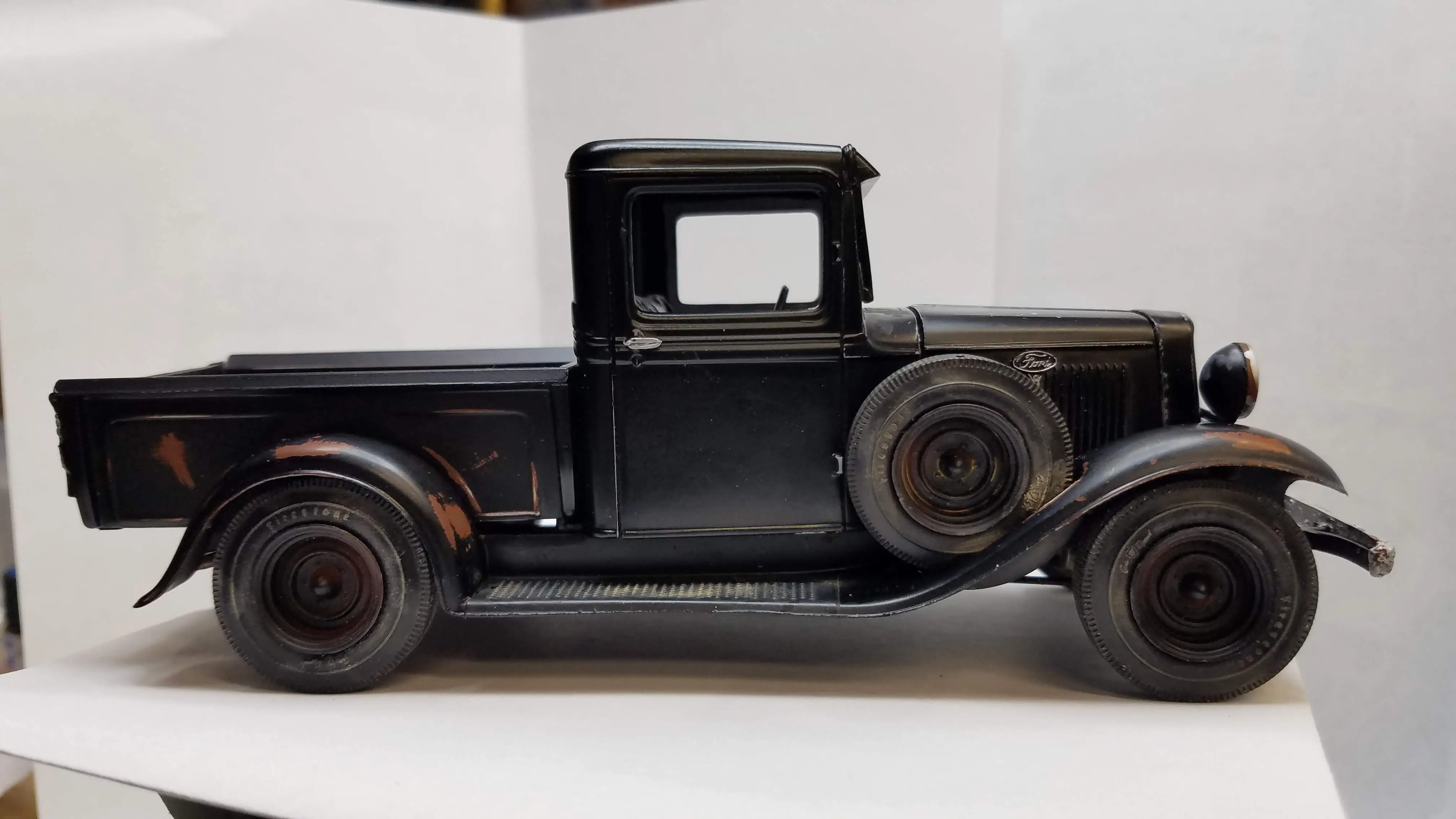
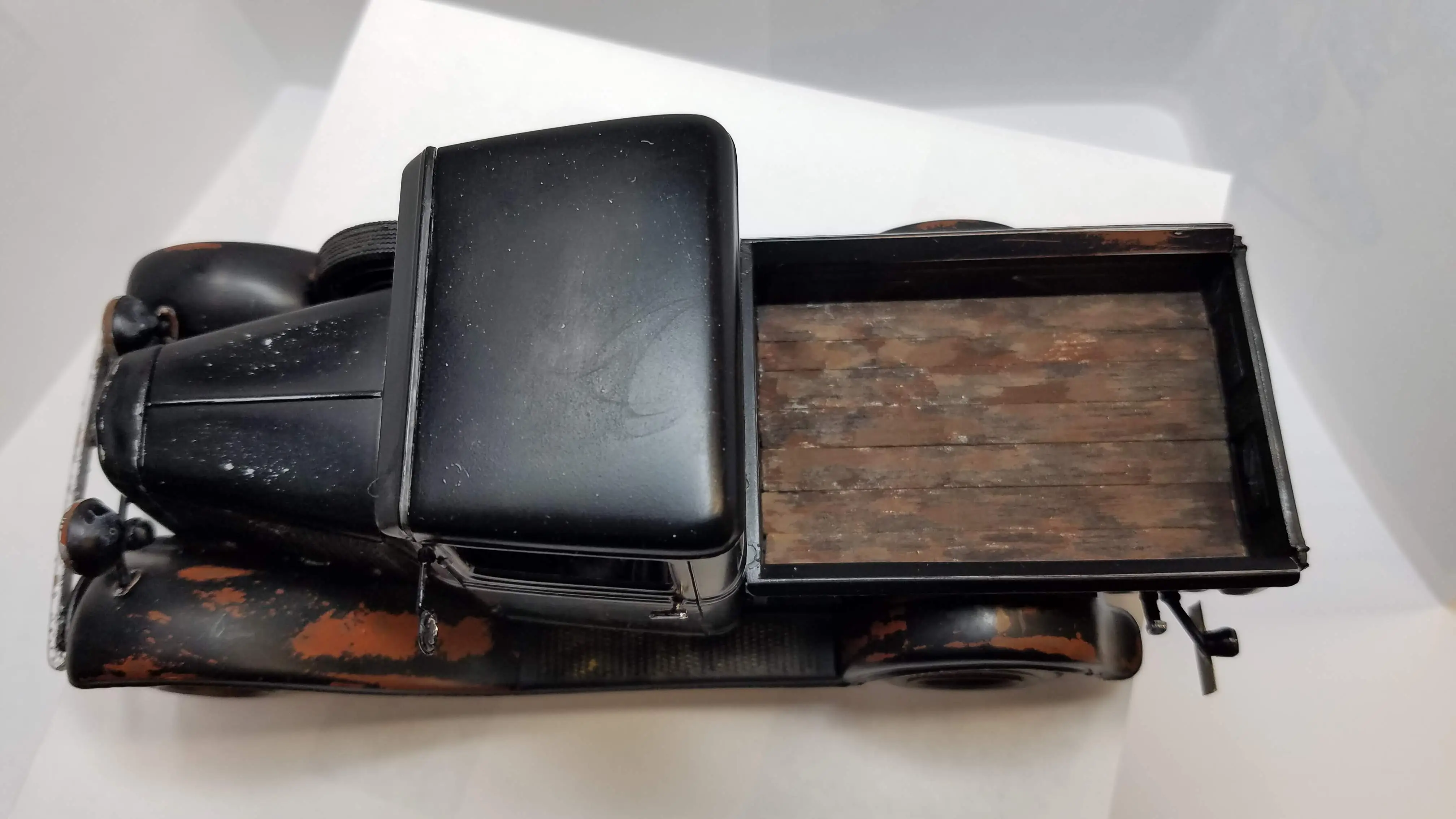
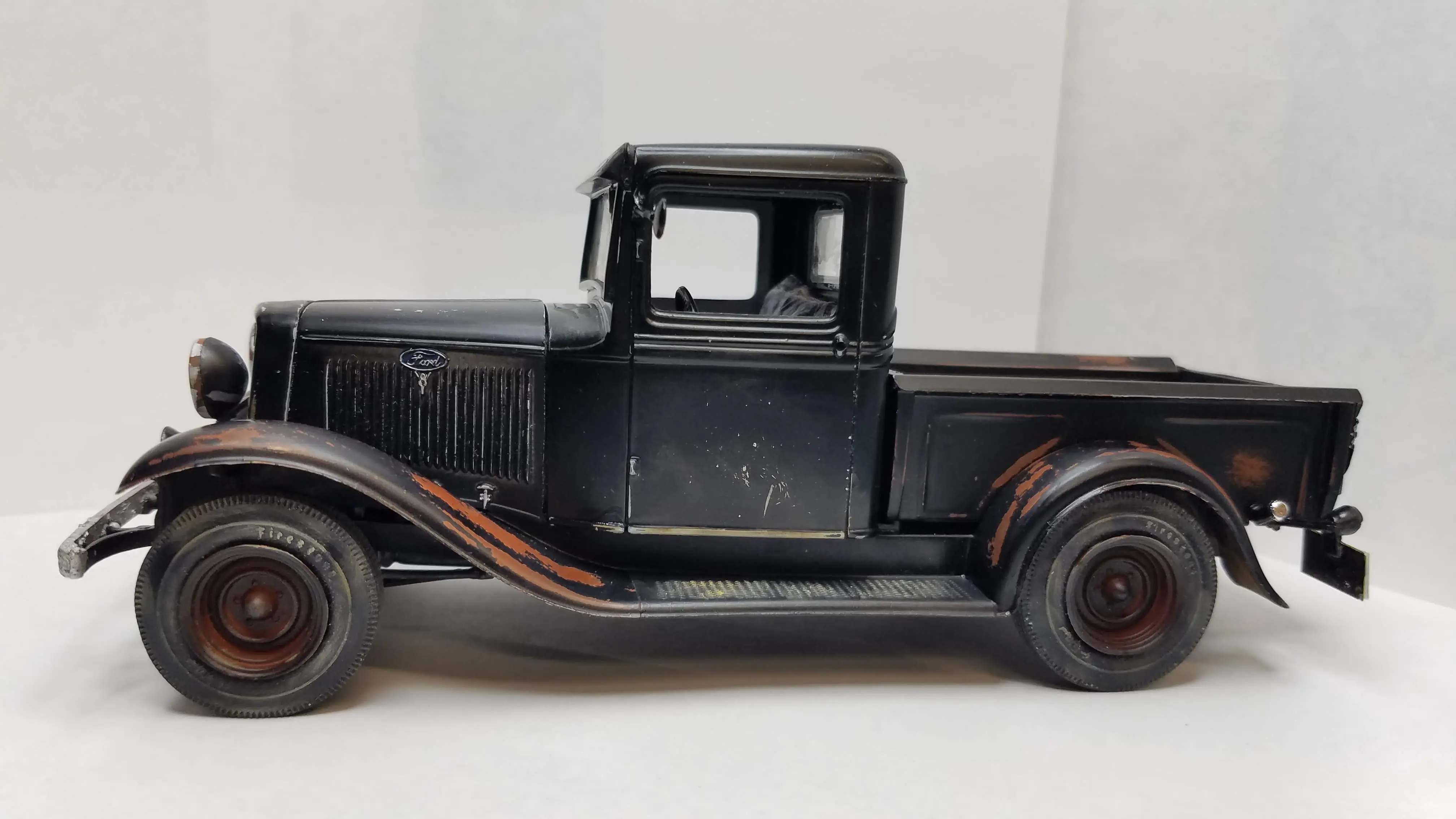
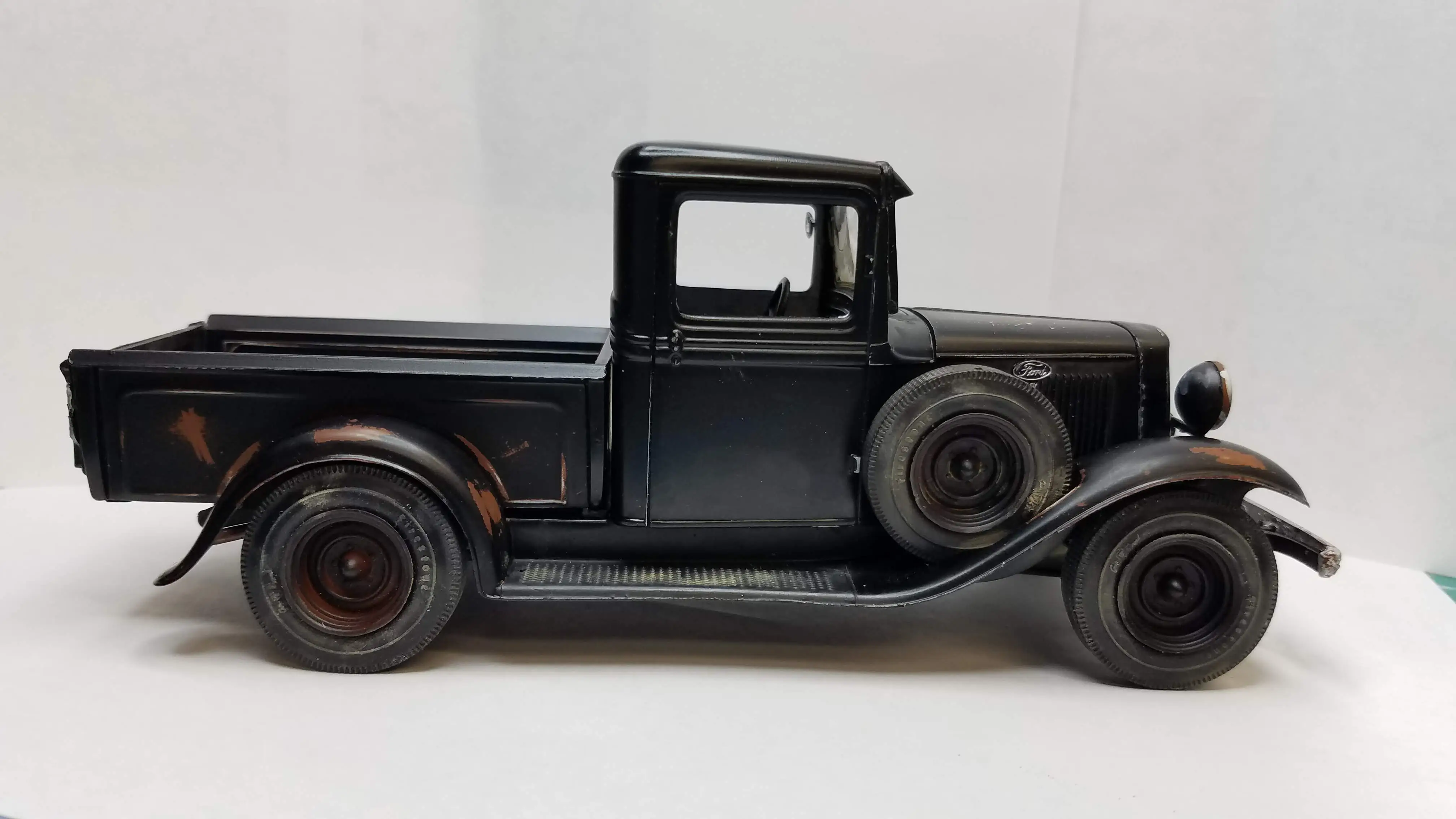
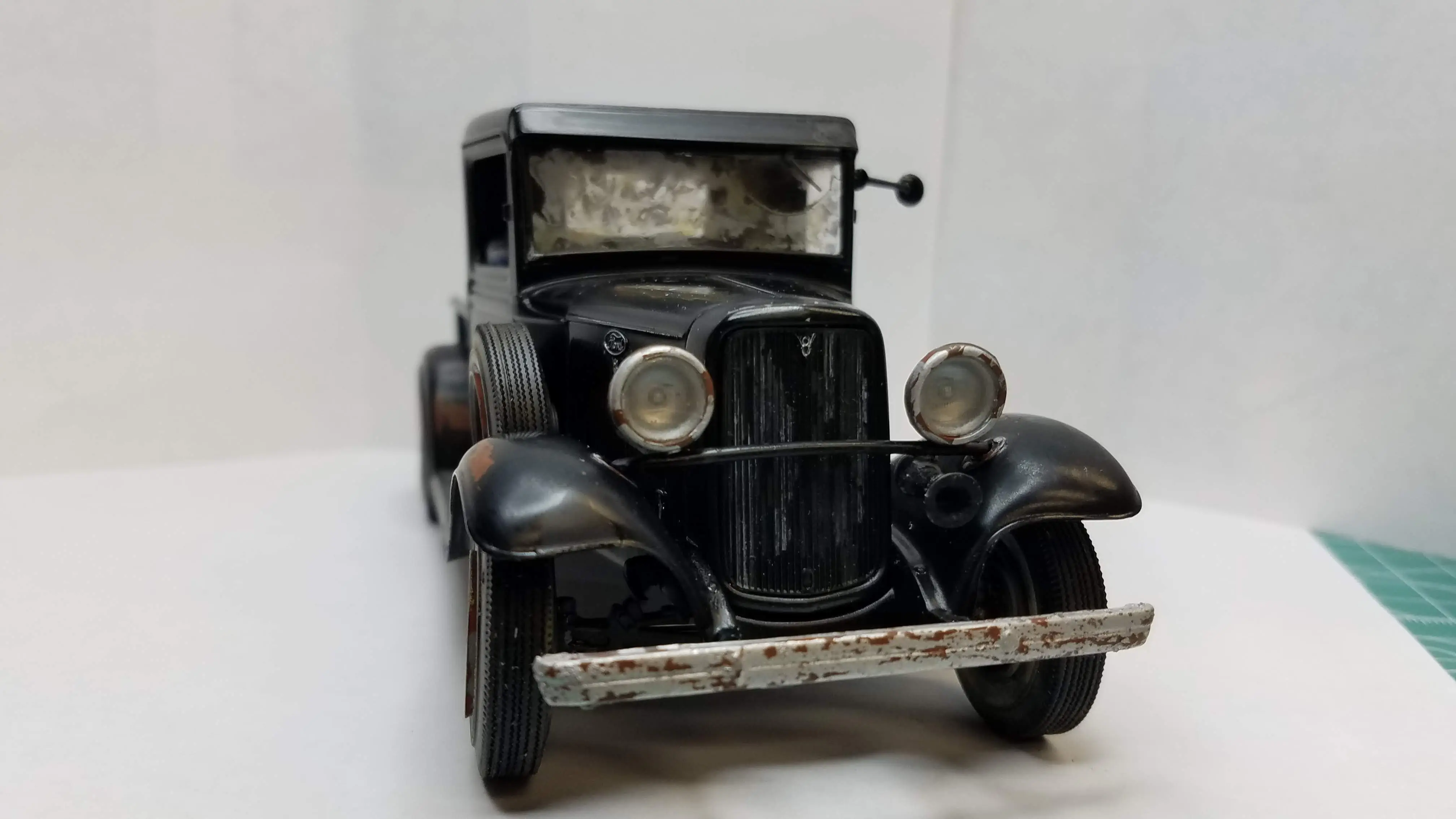 One View of the Finished Model
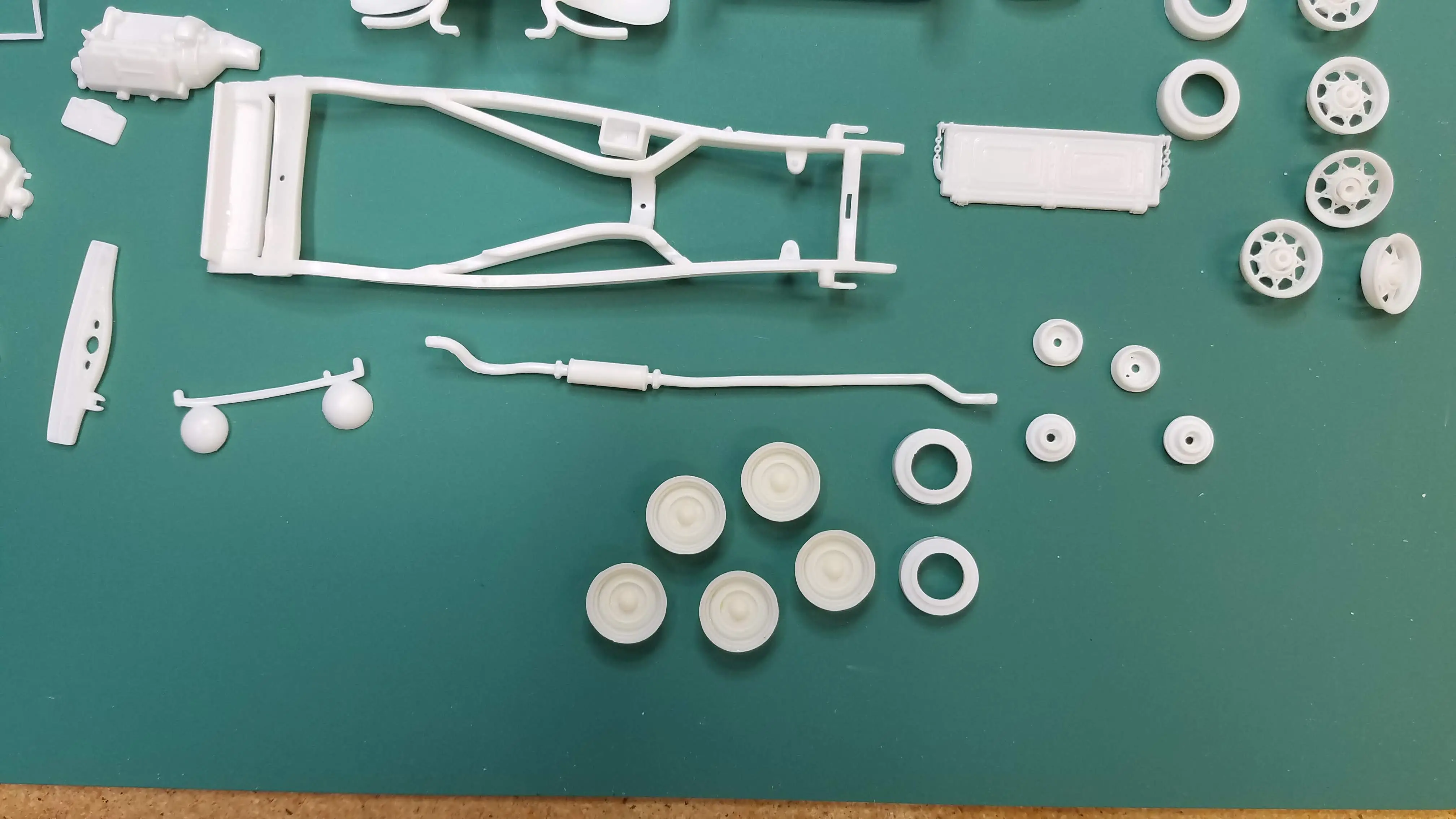
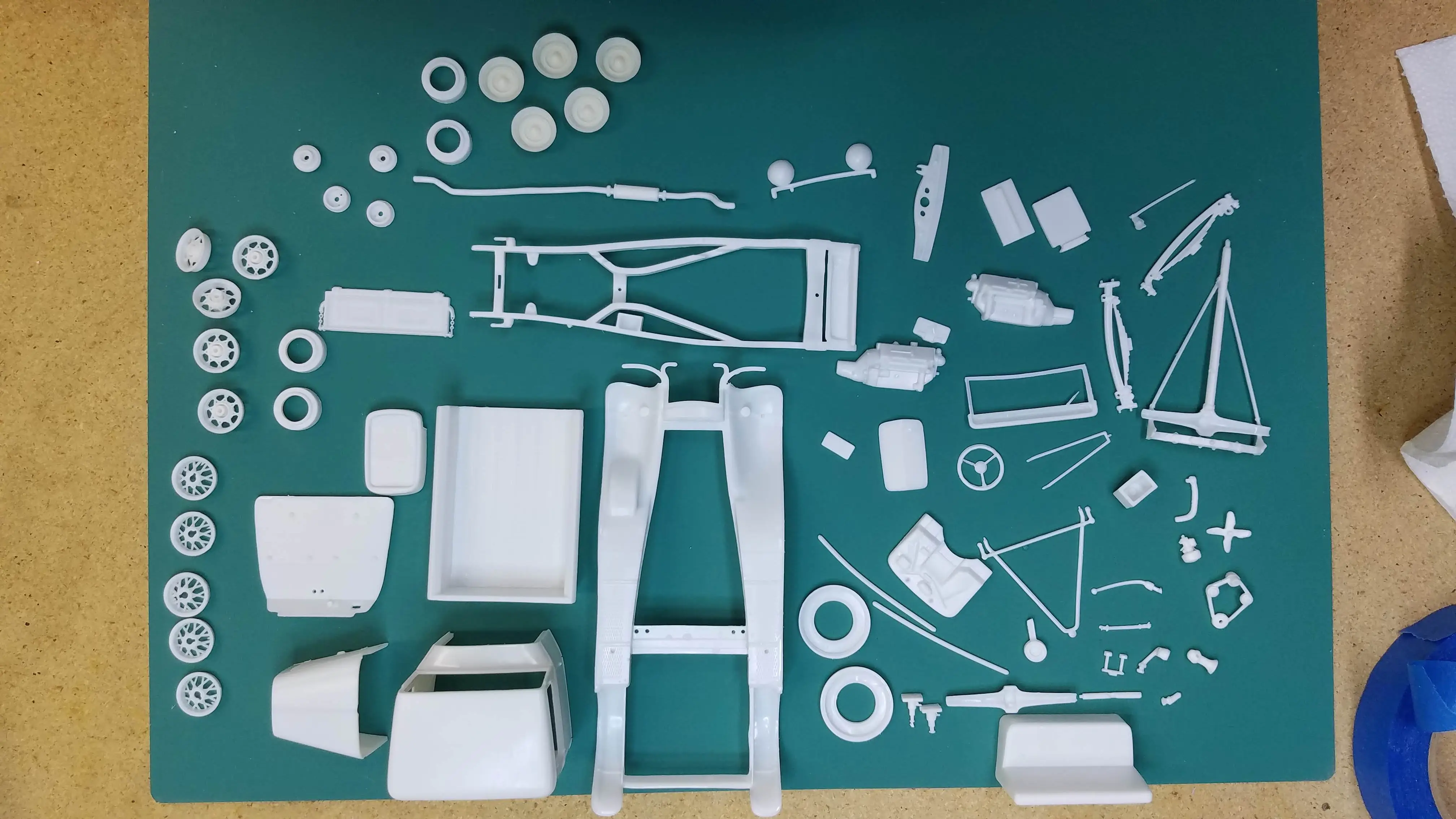 Parts are off the sprews
 Parts are off the sprews
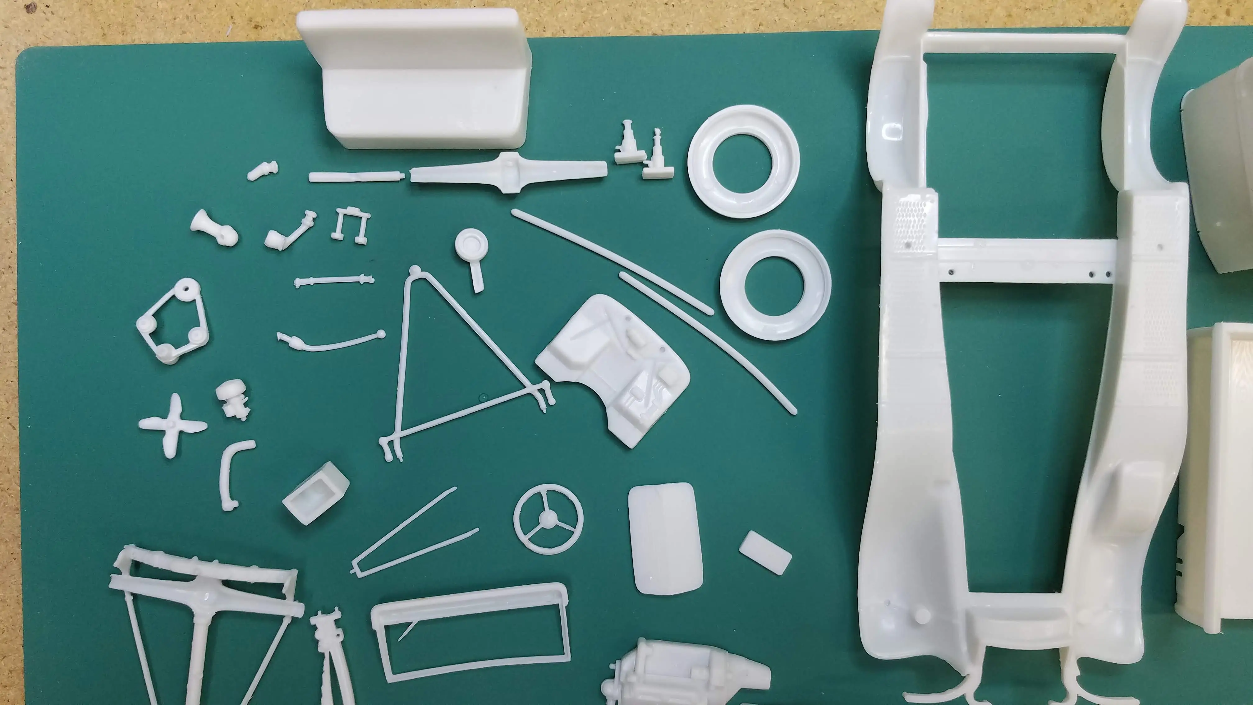
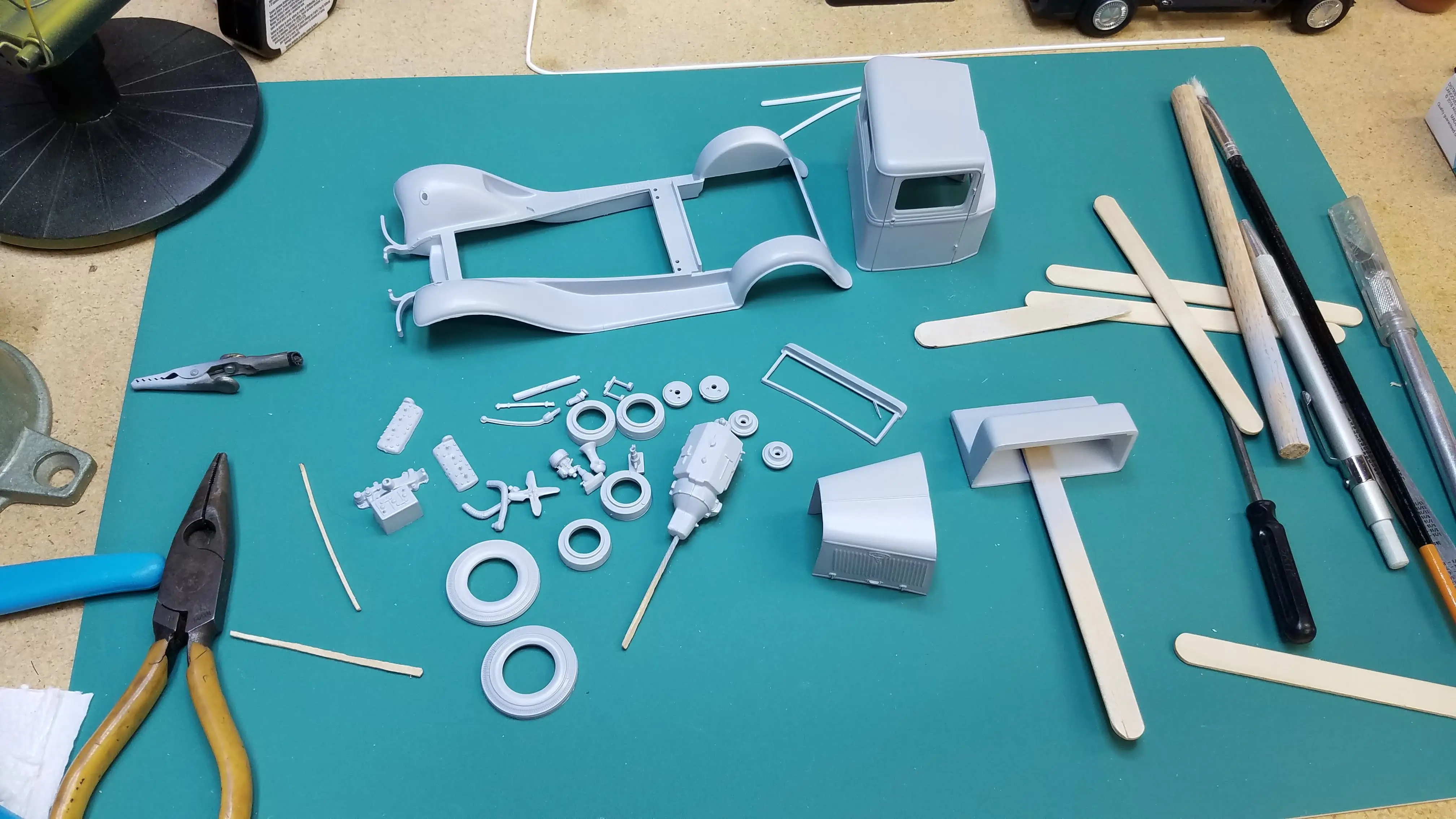
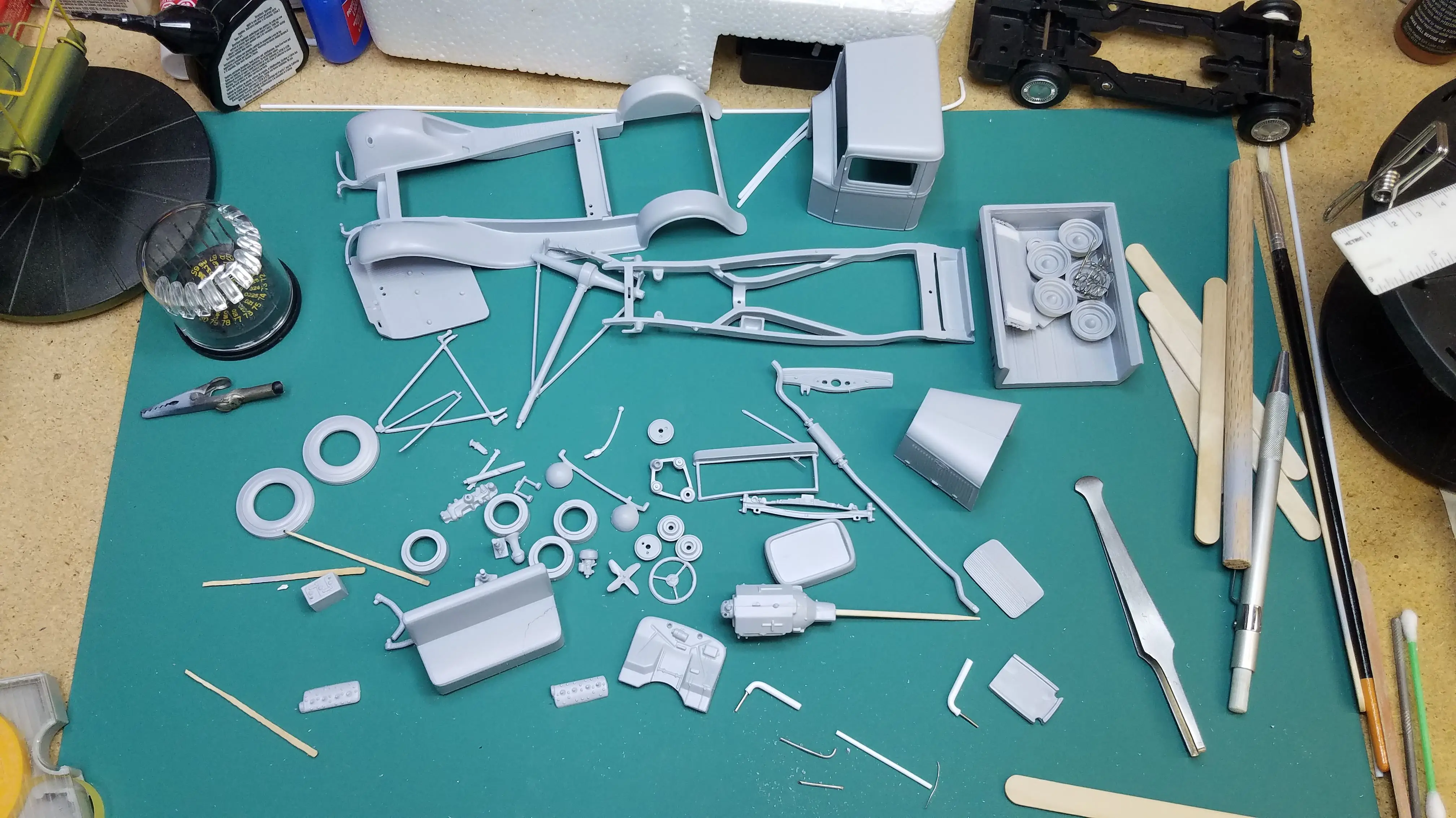
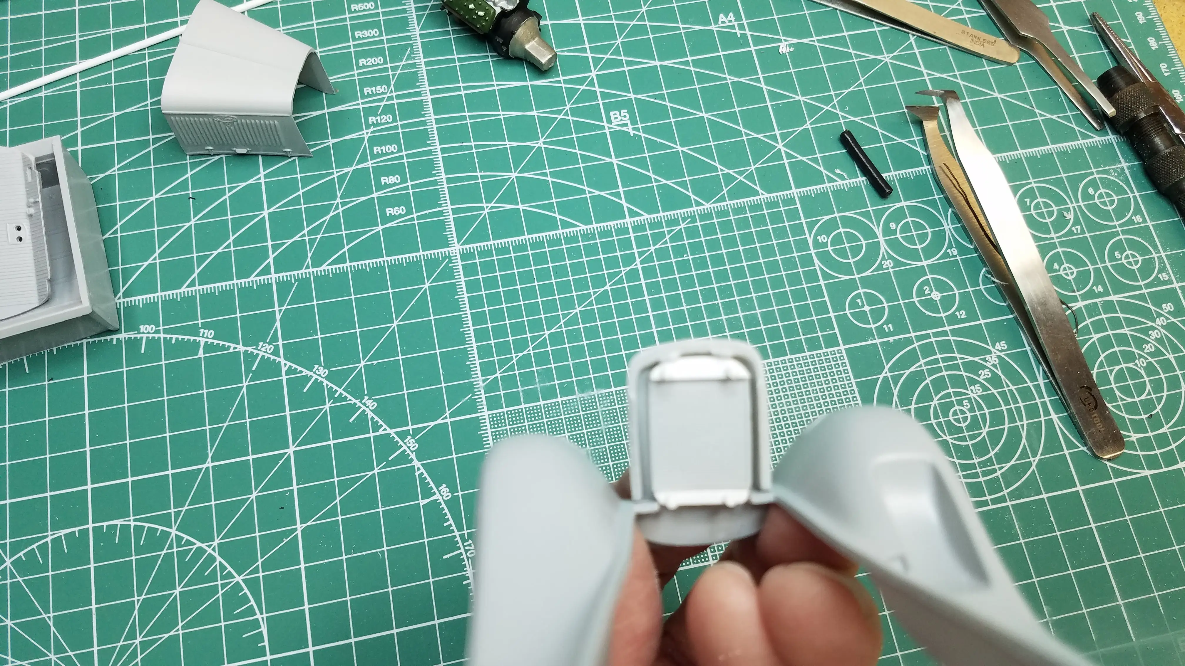
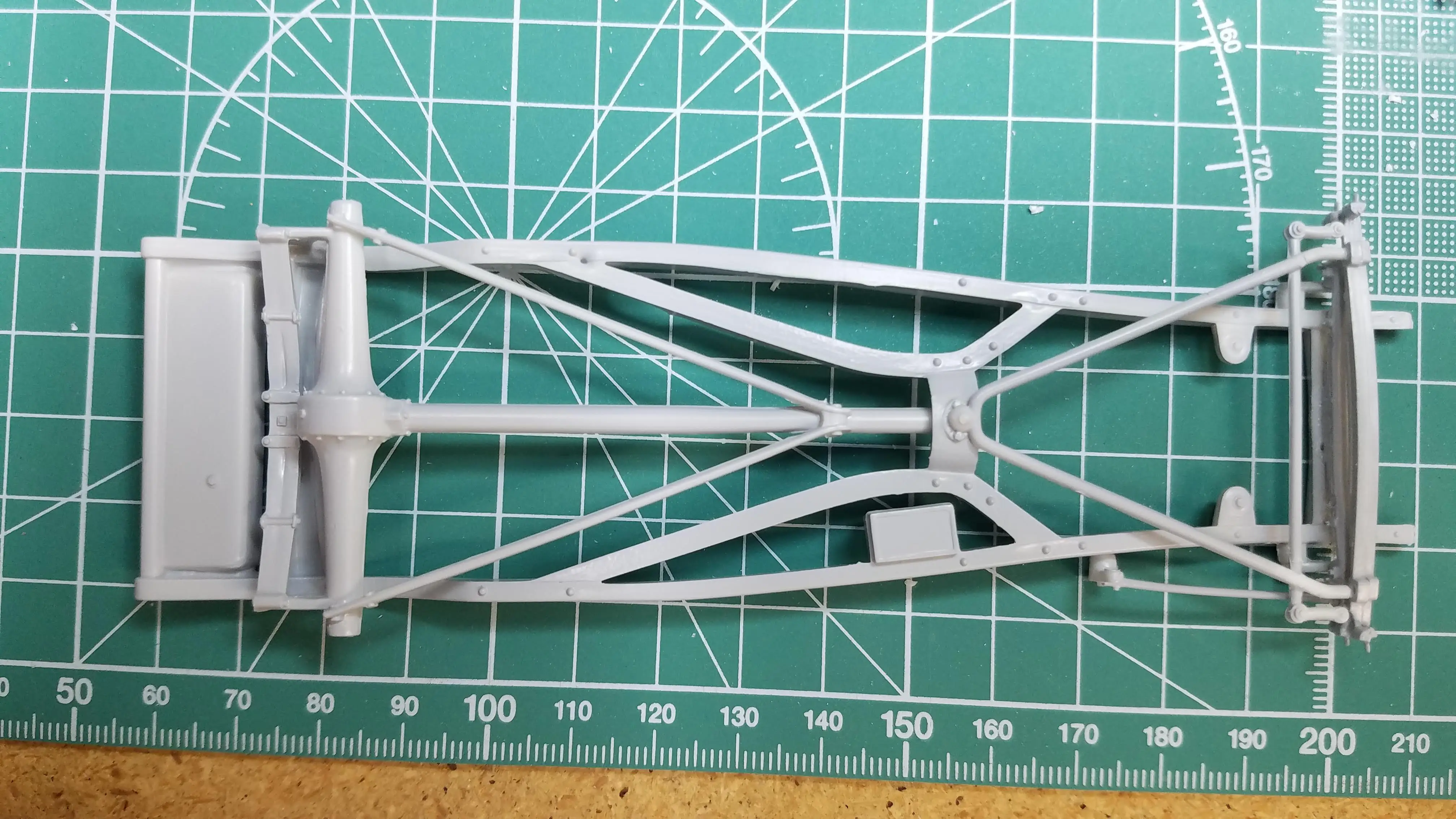
 Needed parts are removed from the sprews
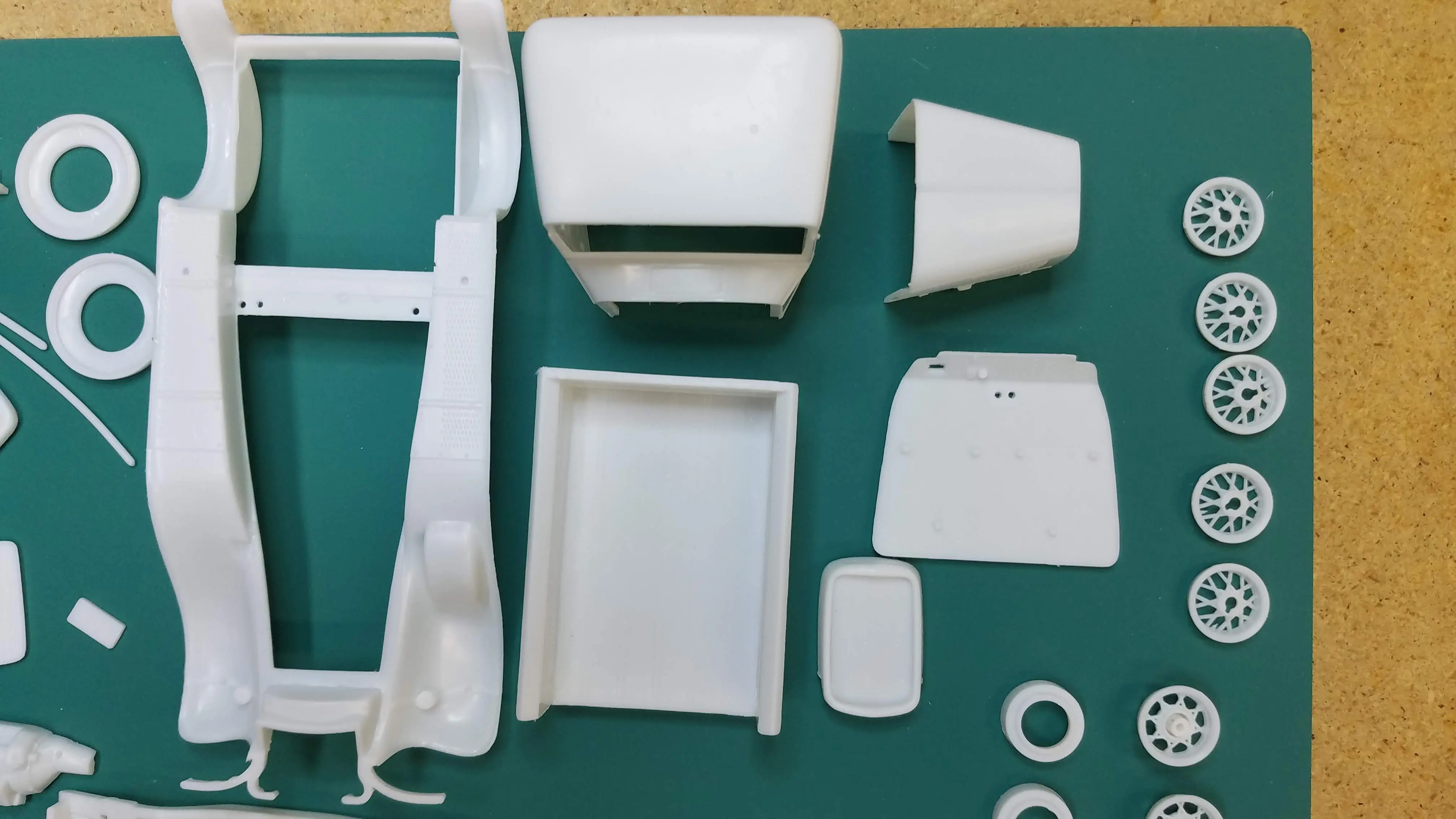 Needed parts are removed from the sprews
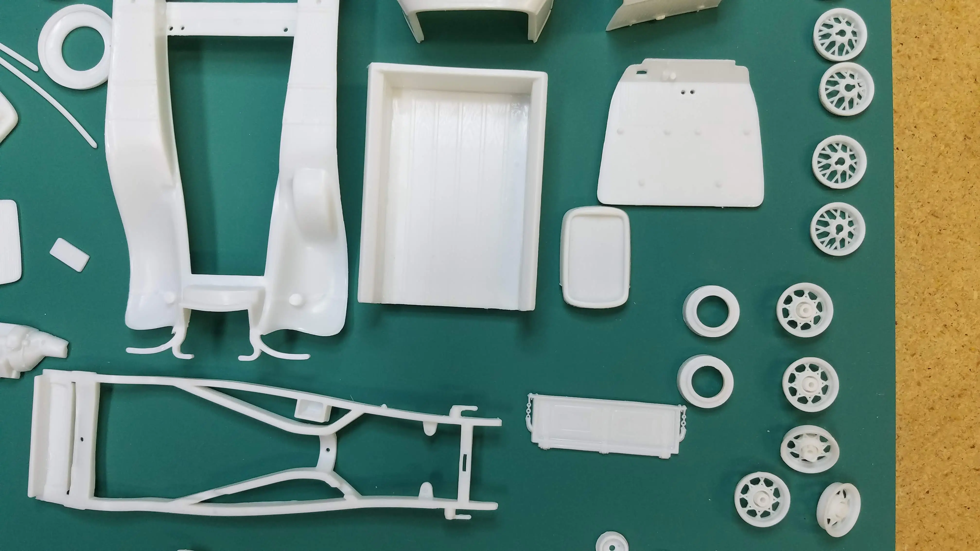 Needed parts are removed from the sprews
 Needed parts are removed from the sprews
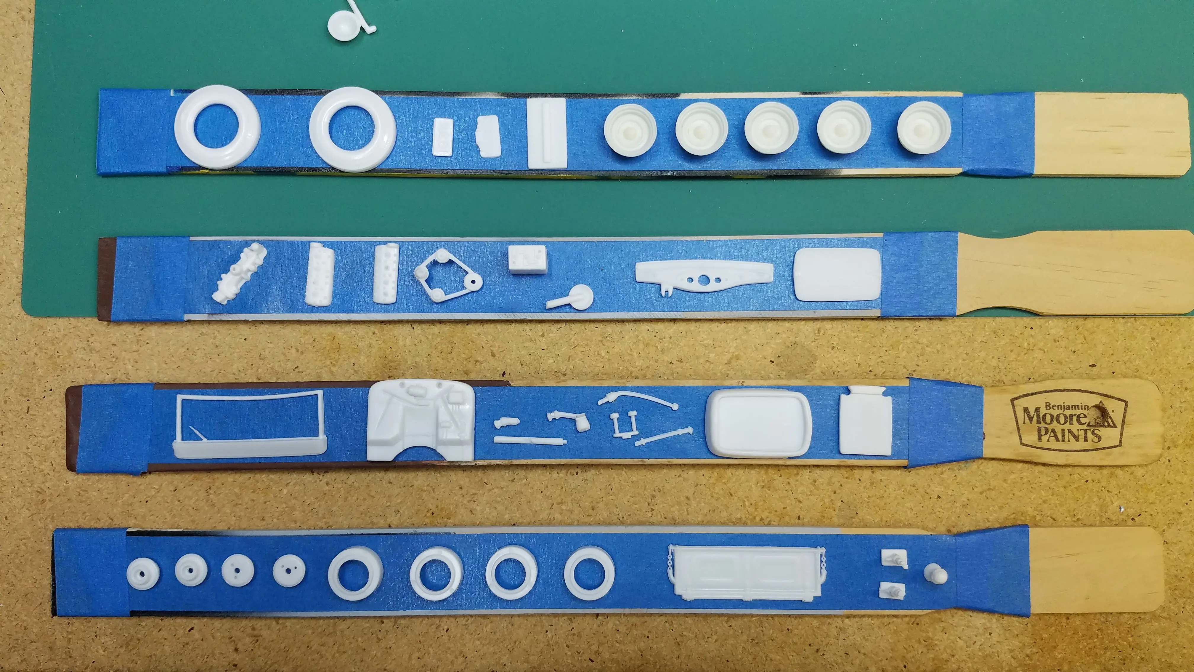
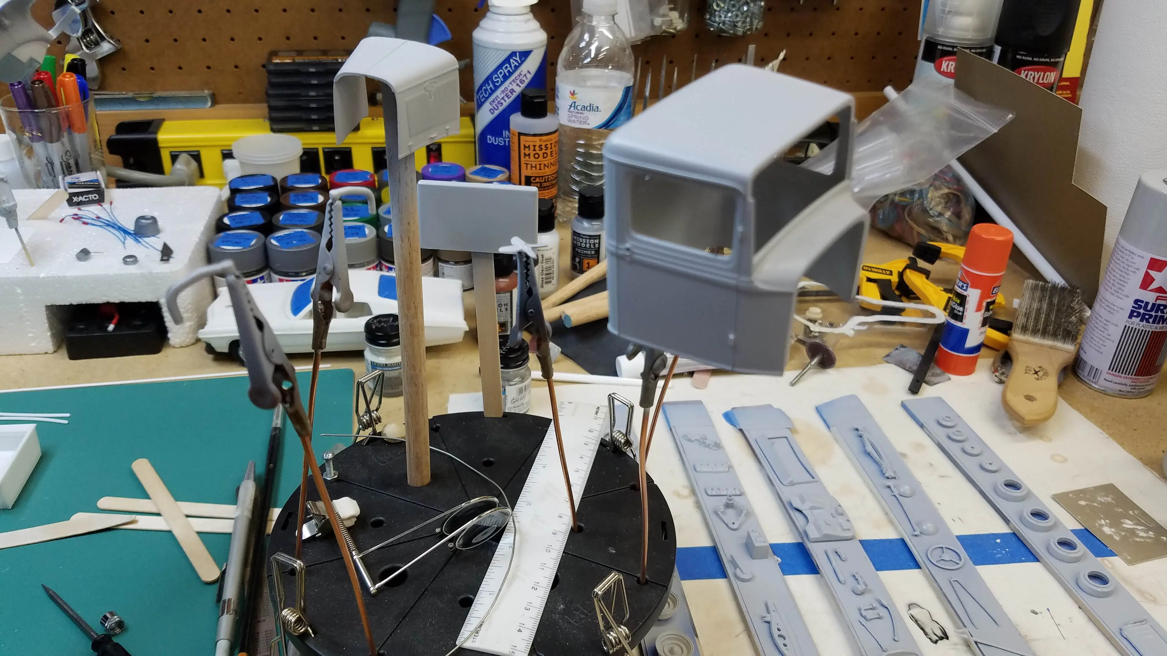
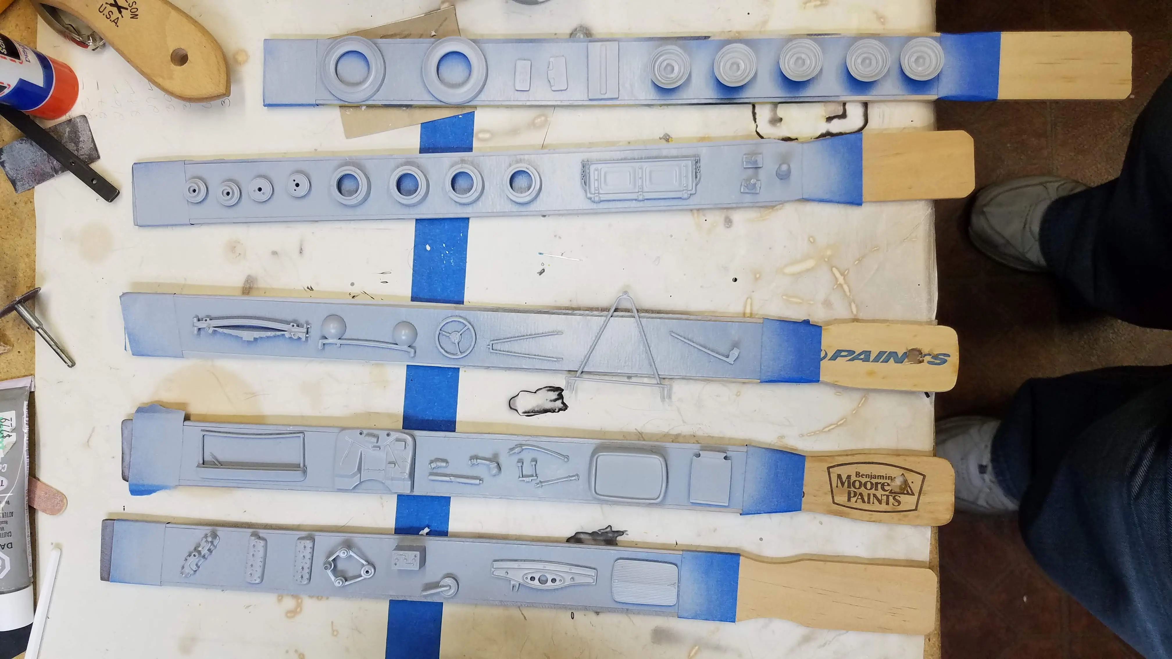
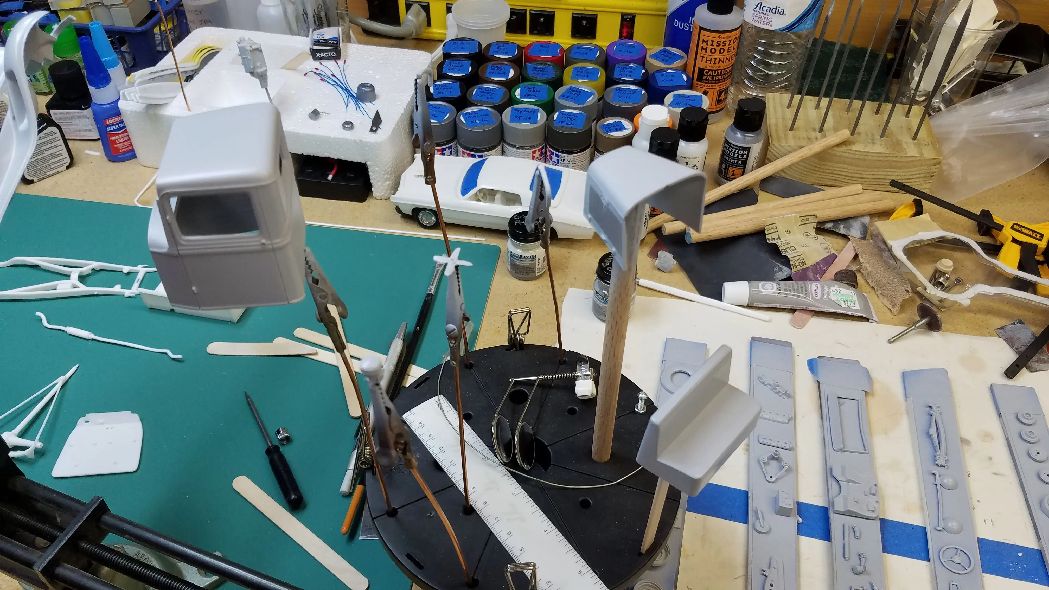
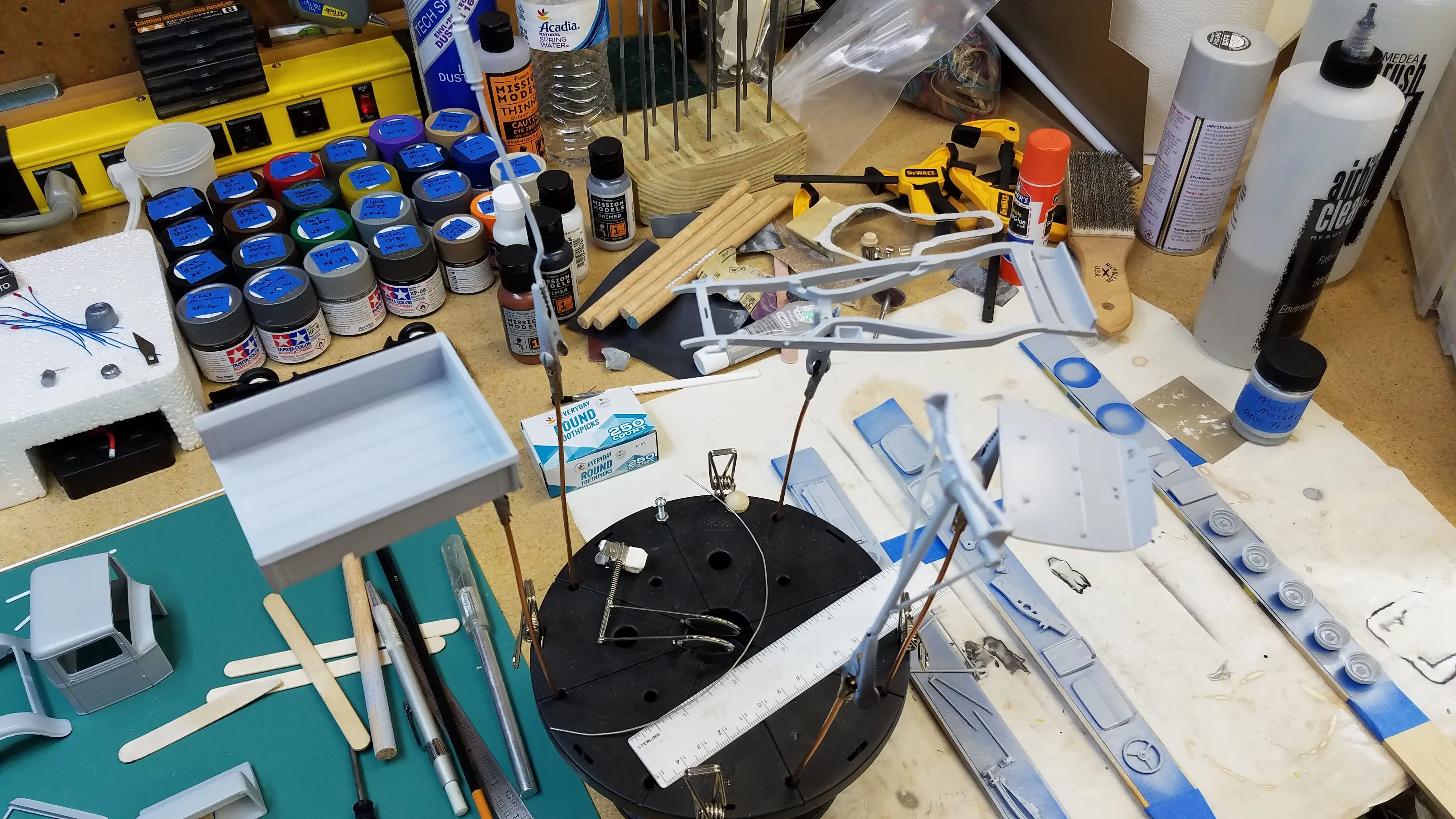
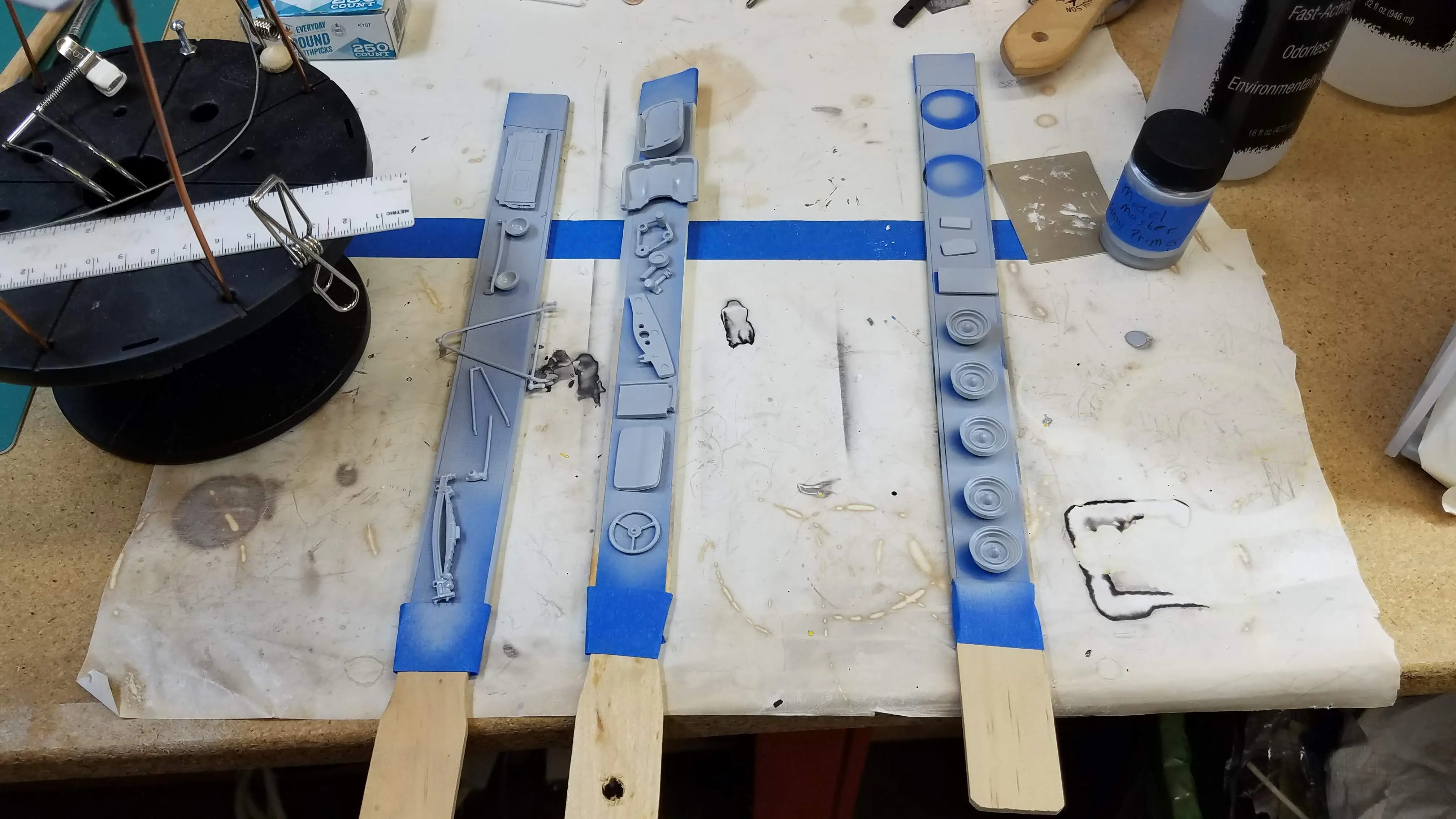
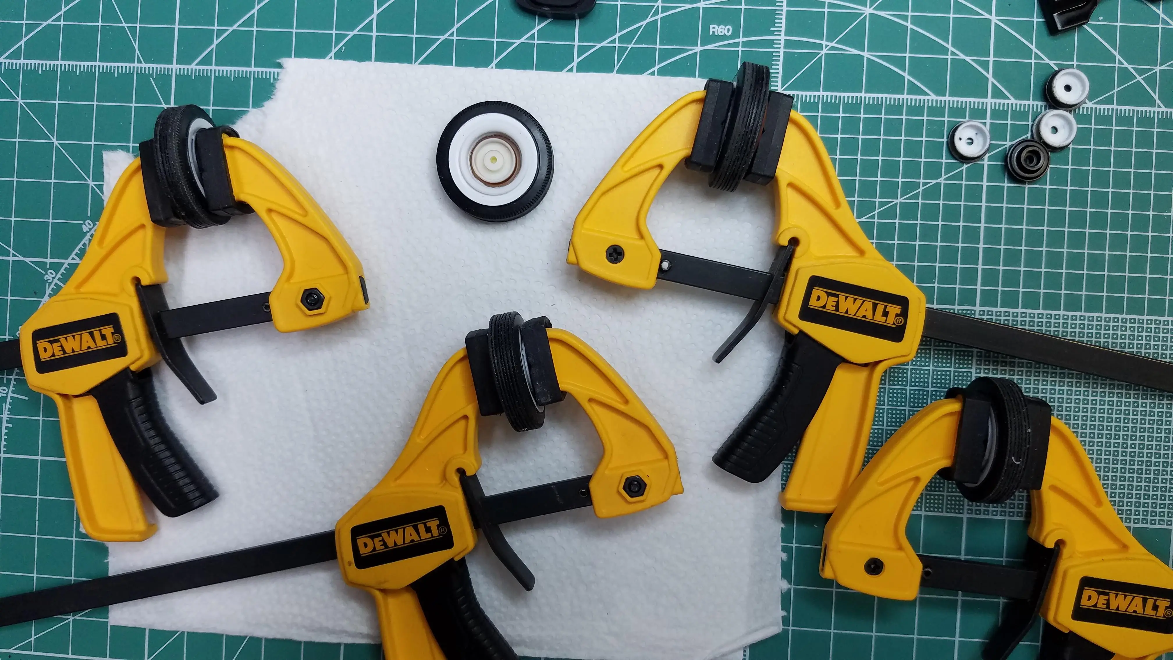
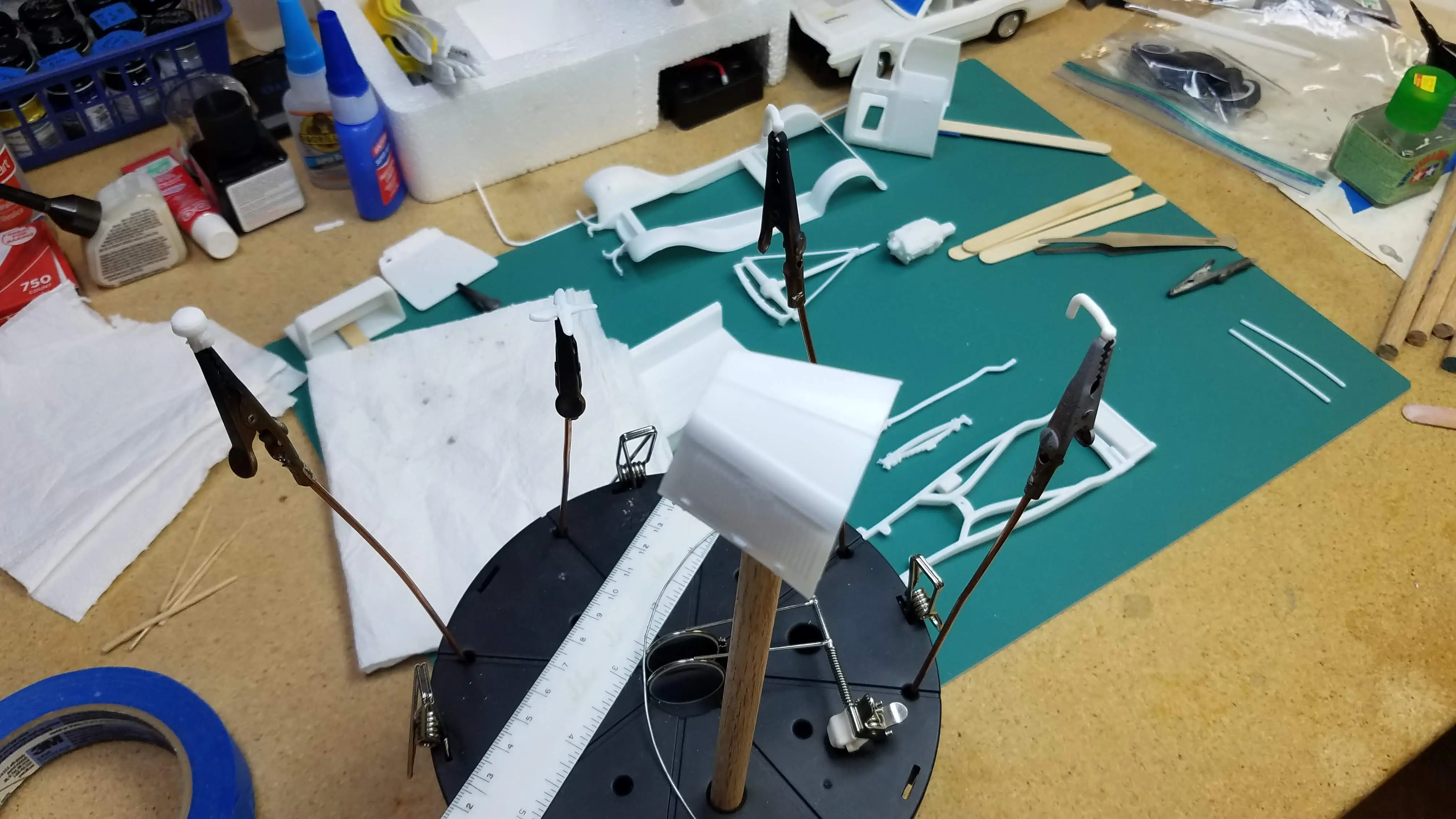 Parts being prep'ed for primer
 Parts being prep'ed for primer
 Parts being prep'ed for primer
 Parts being prep'ed for primer
 Parts being prep'ed for primer
 Parts being prep'ed for primer
 Parts being prep'ed for primer
 Parts being prep'ed for primer
 Cleaning parts after priming
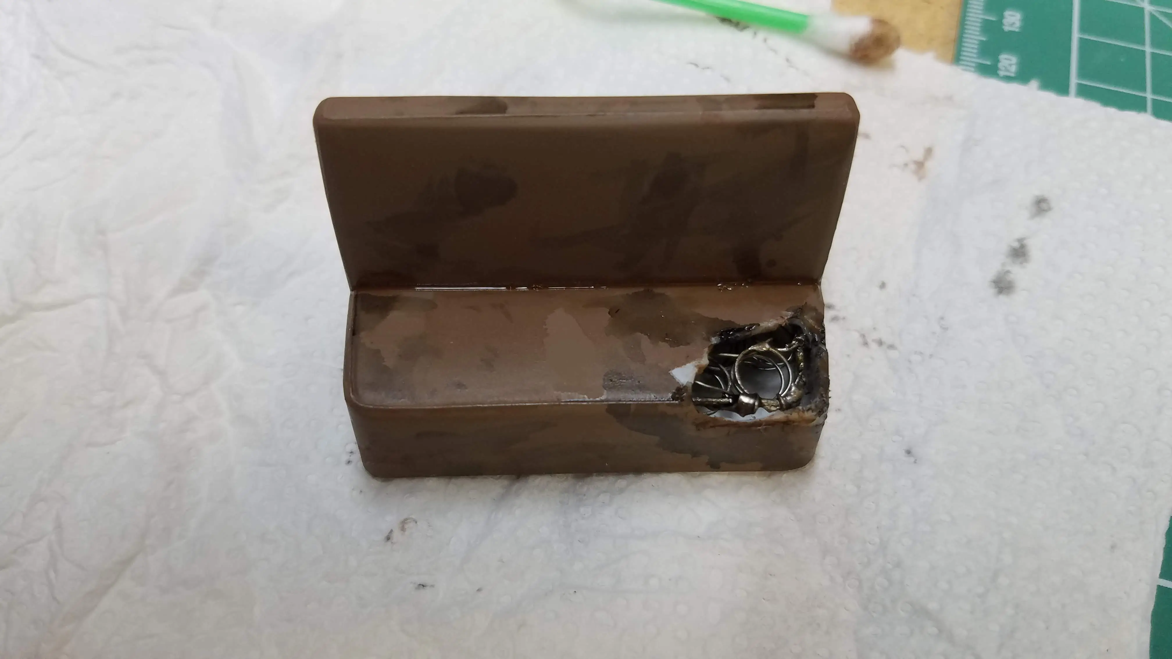
 Scratch building some additional engine parts
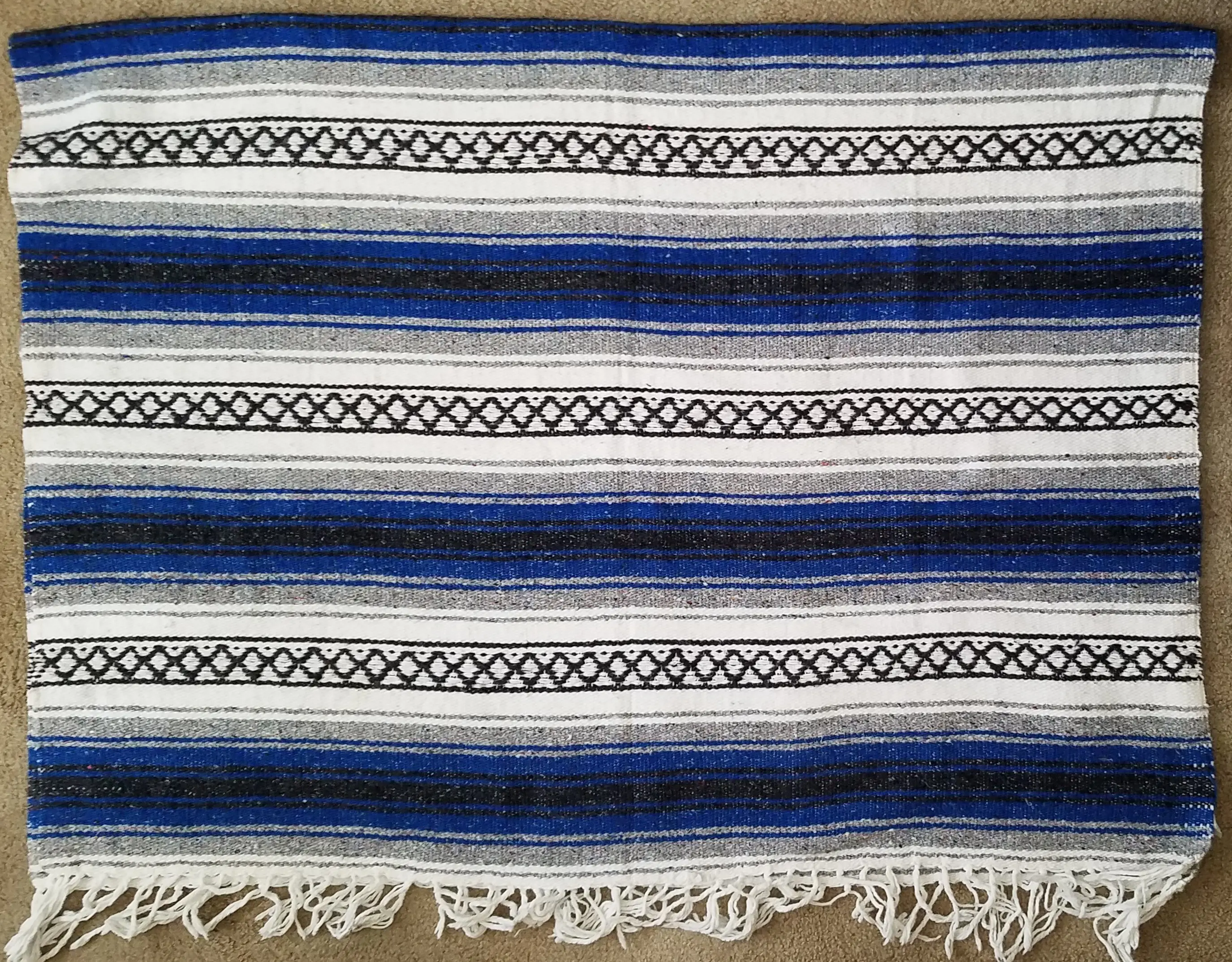
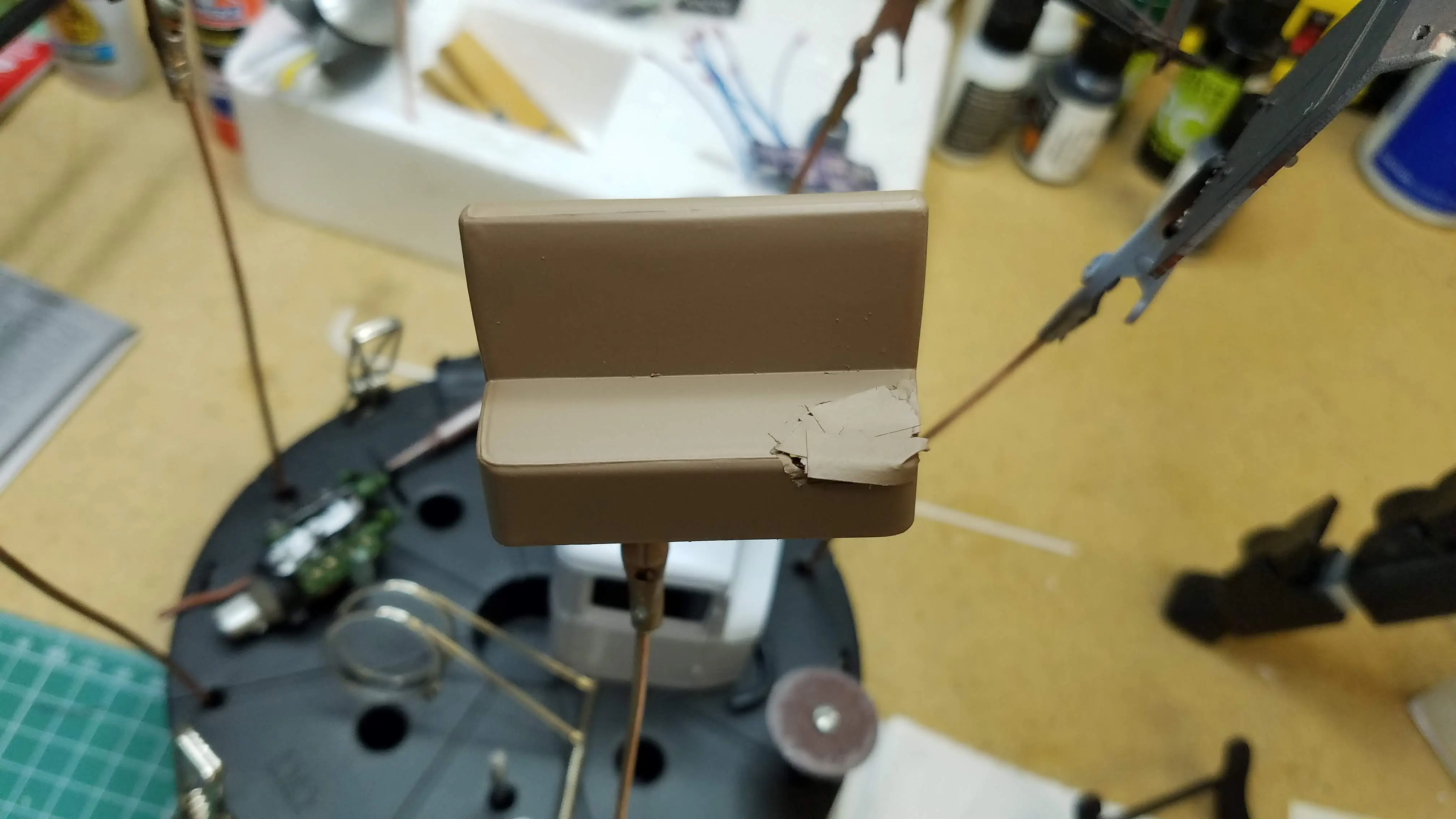
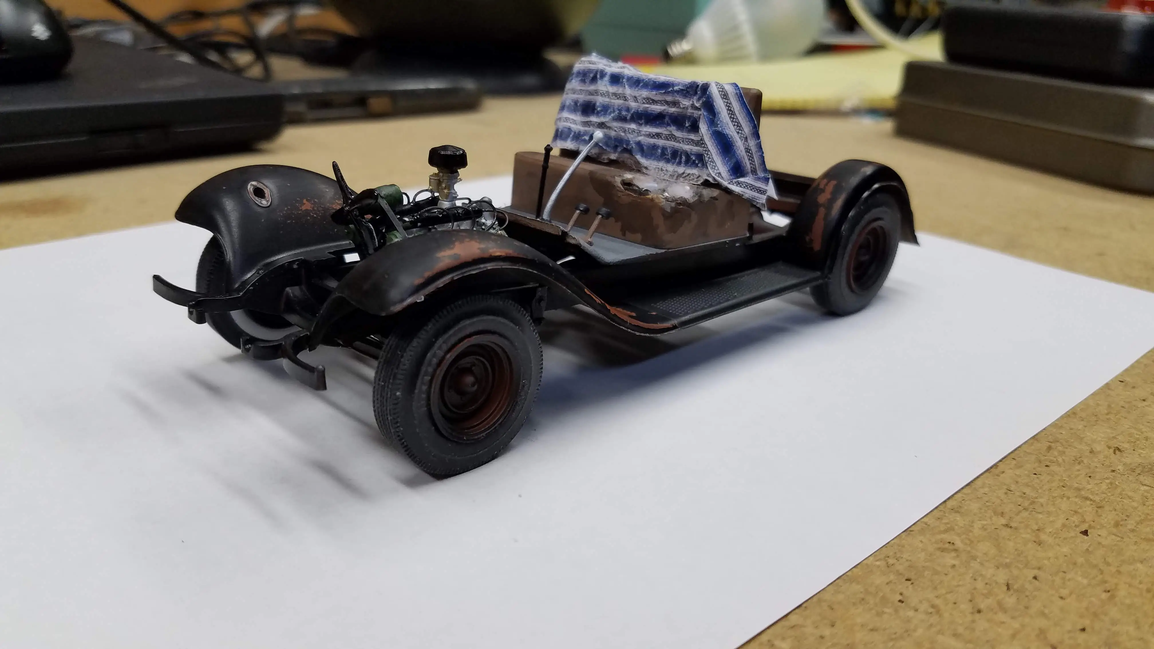
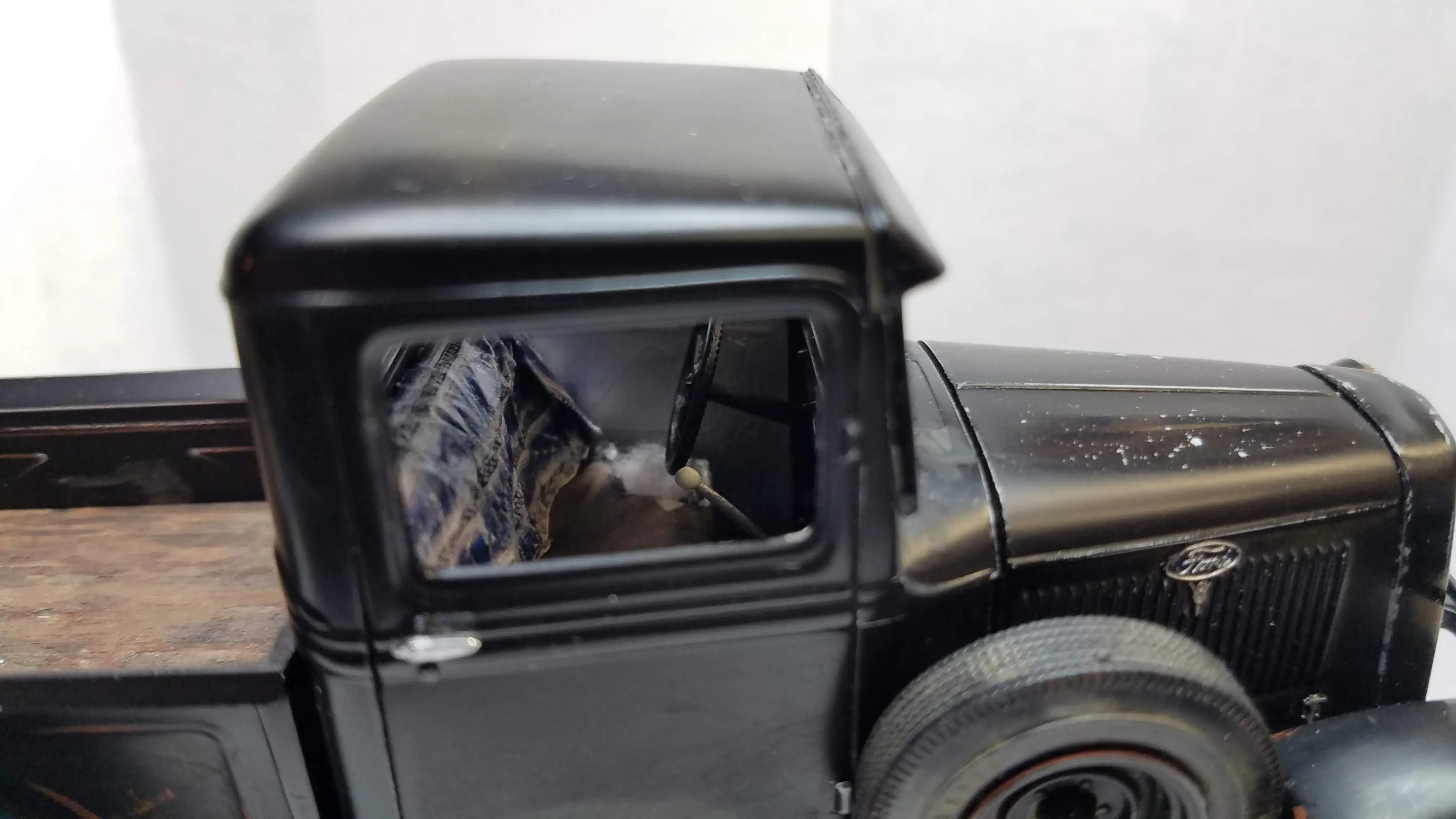
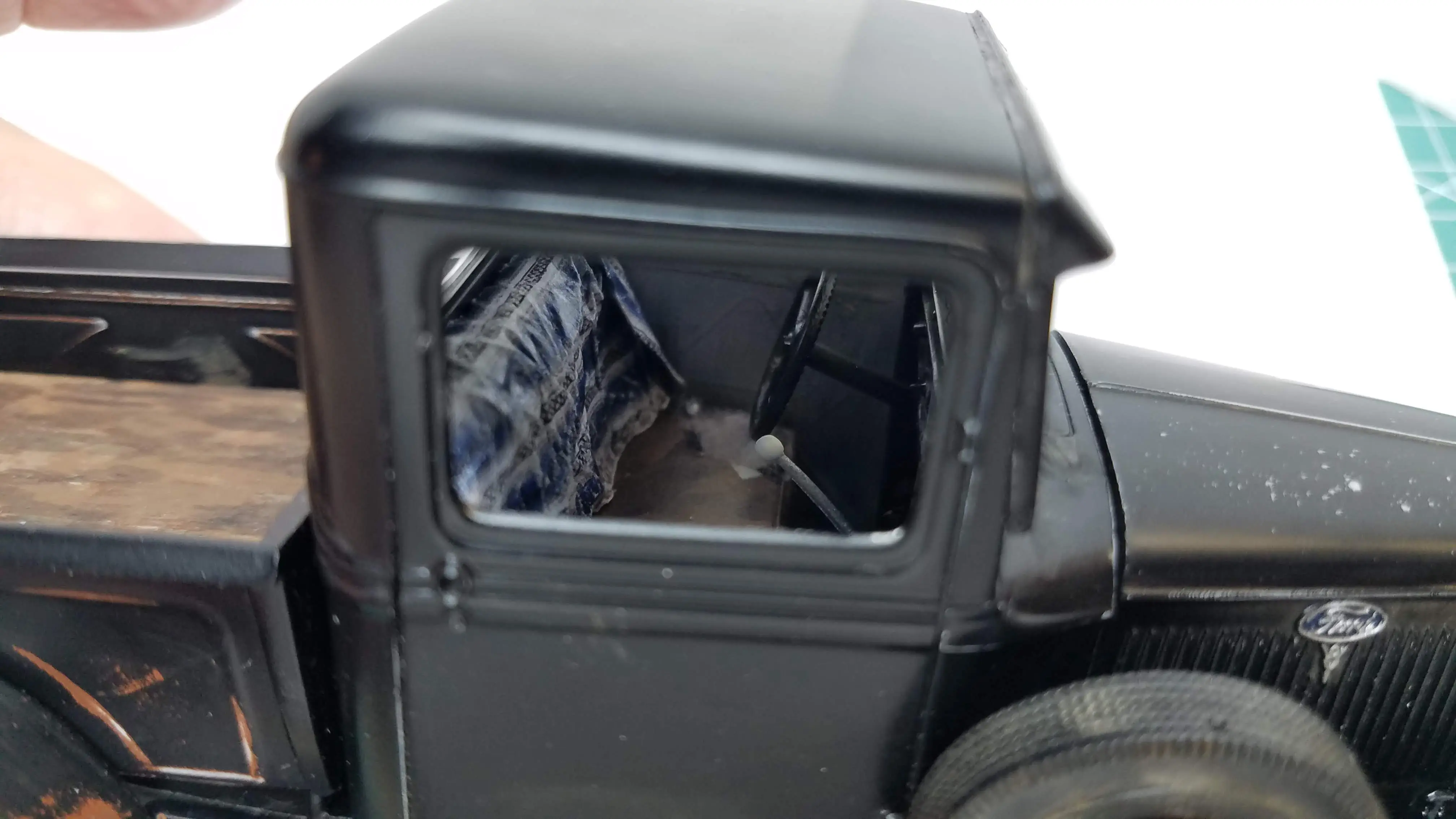
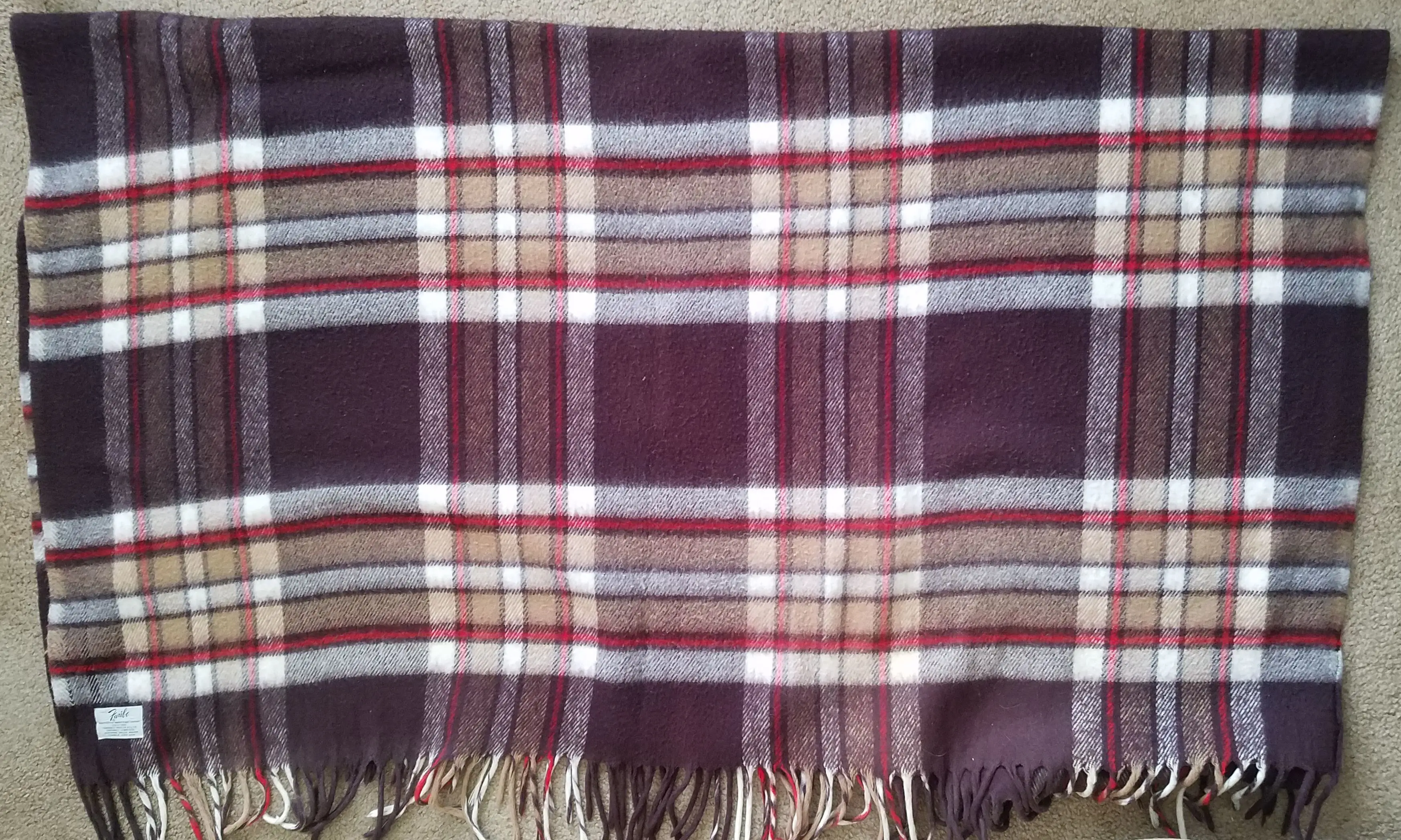 Choosing a blanket to cover the front seat
 Choosing a blanket to cover the front seat
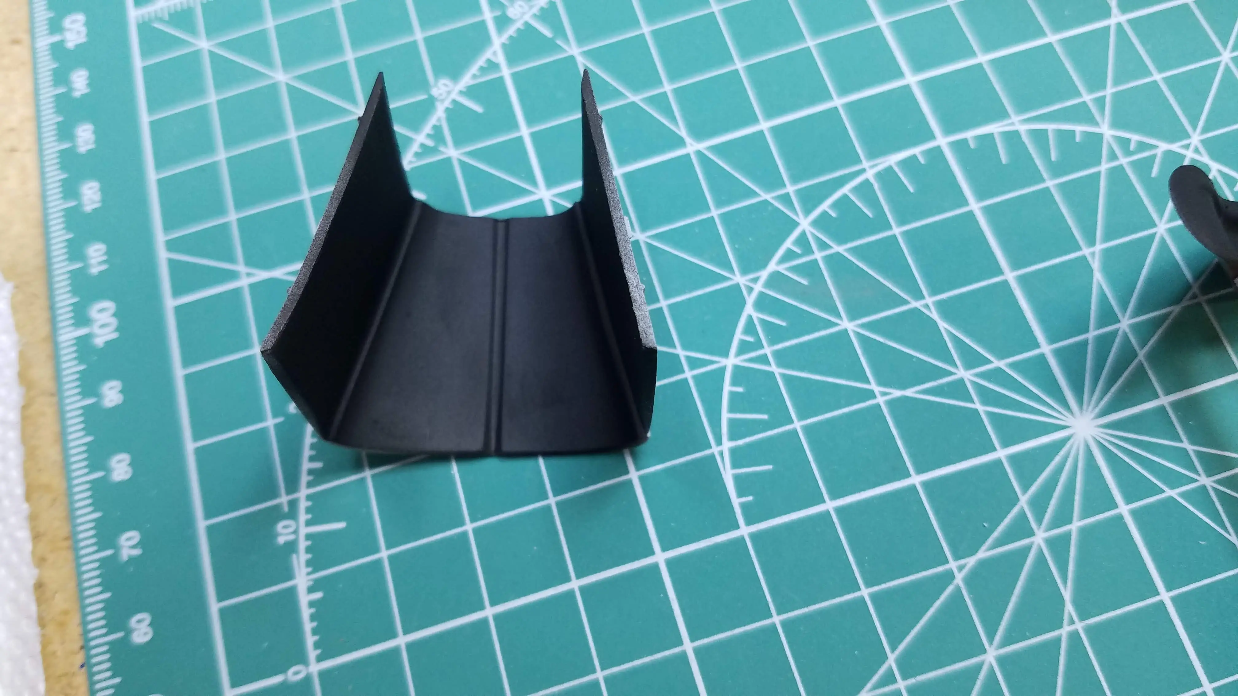
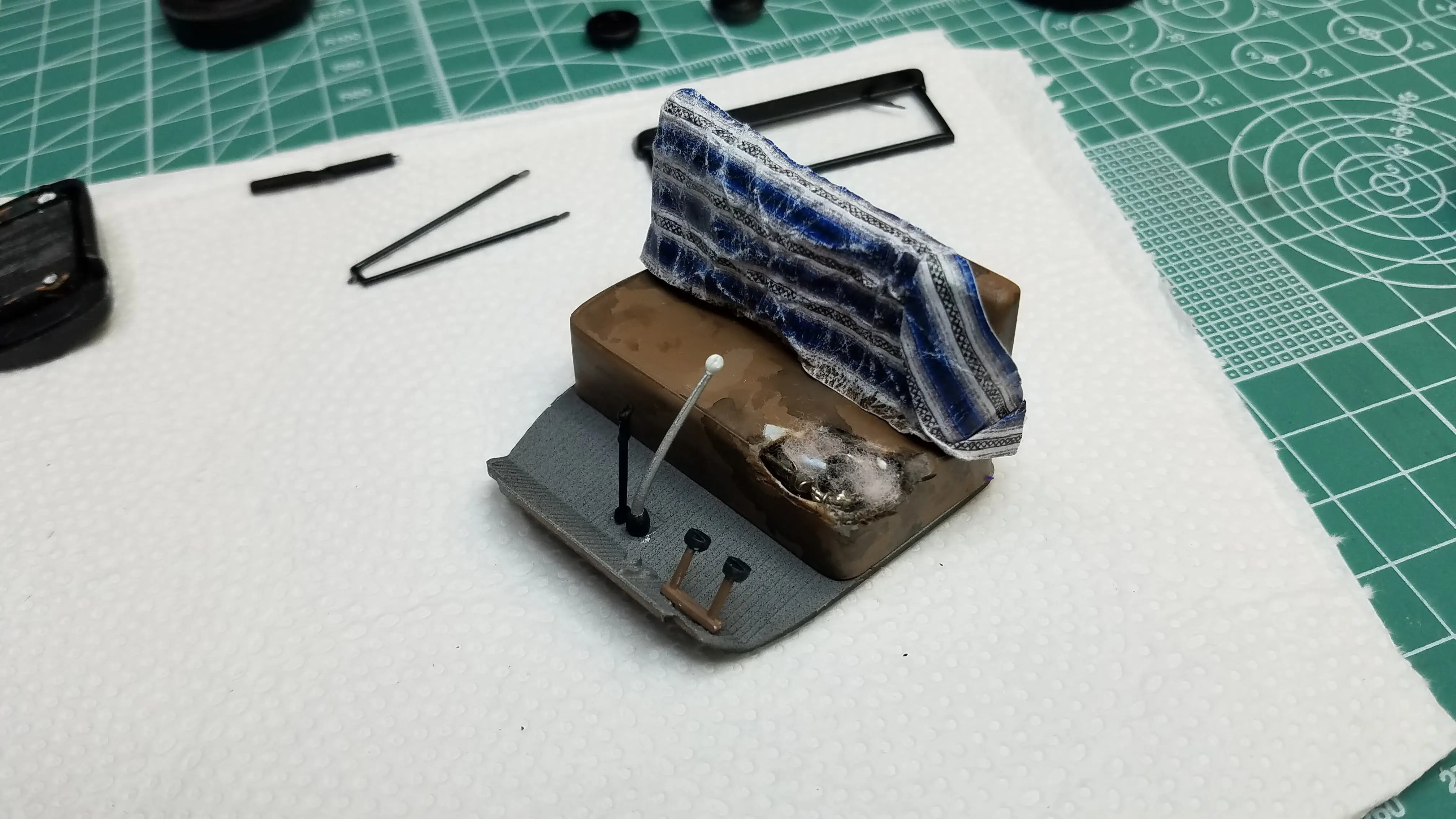
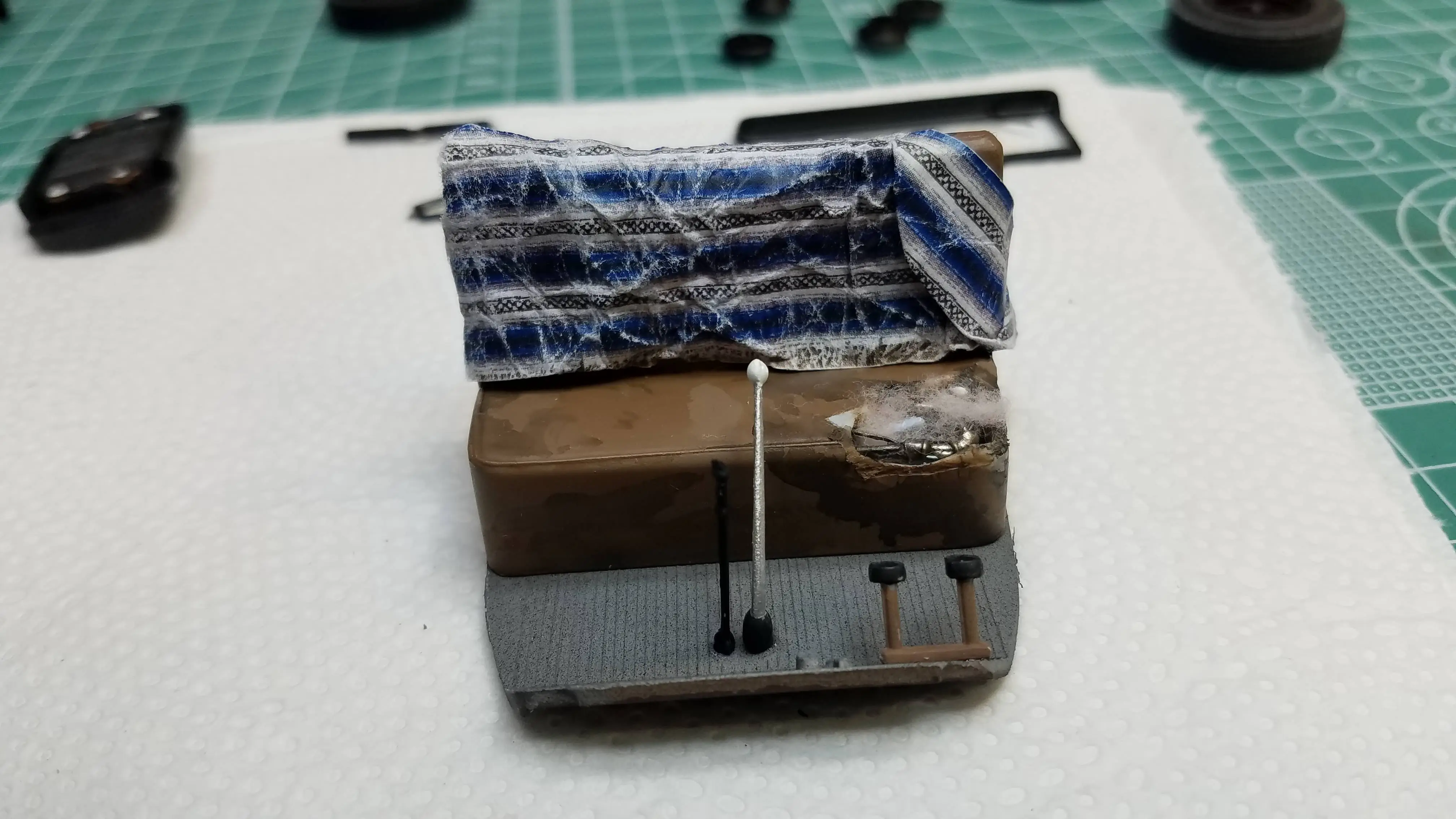
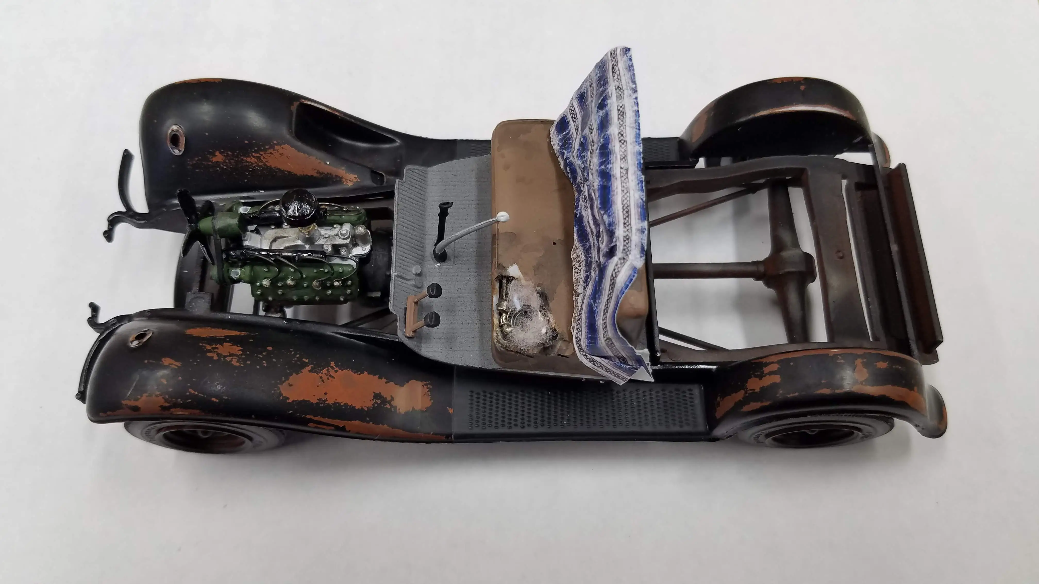
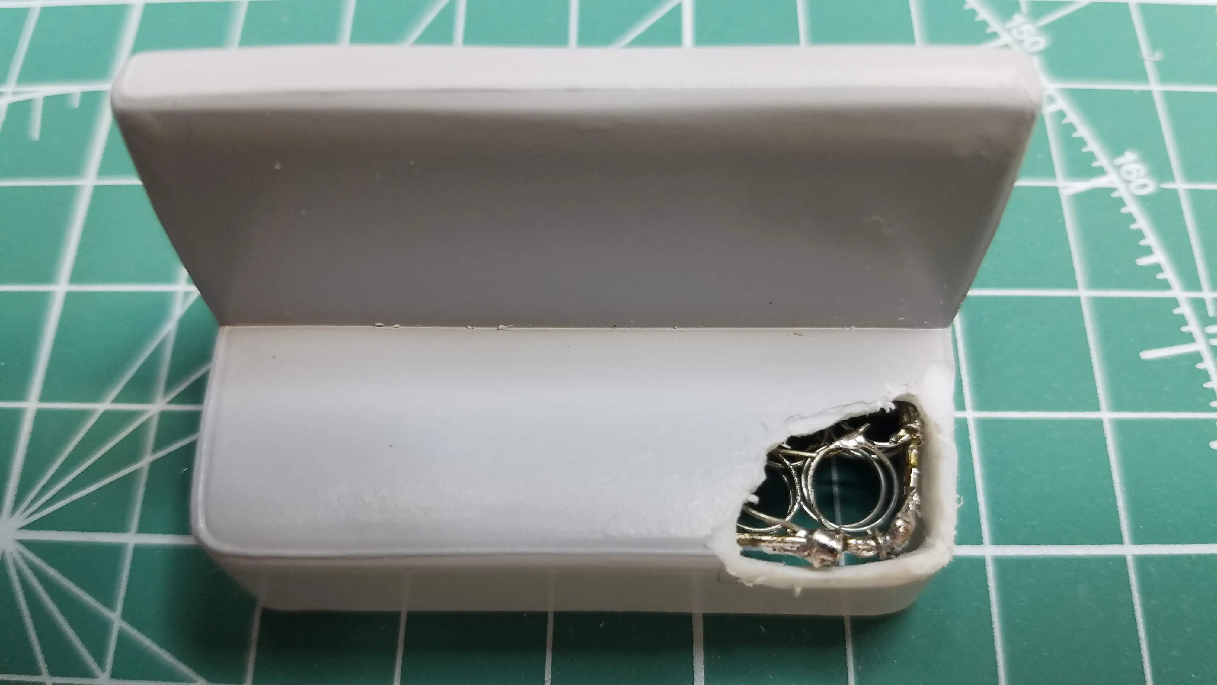 Making a torn seat with seat springs, top view
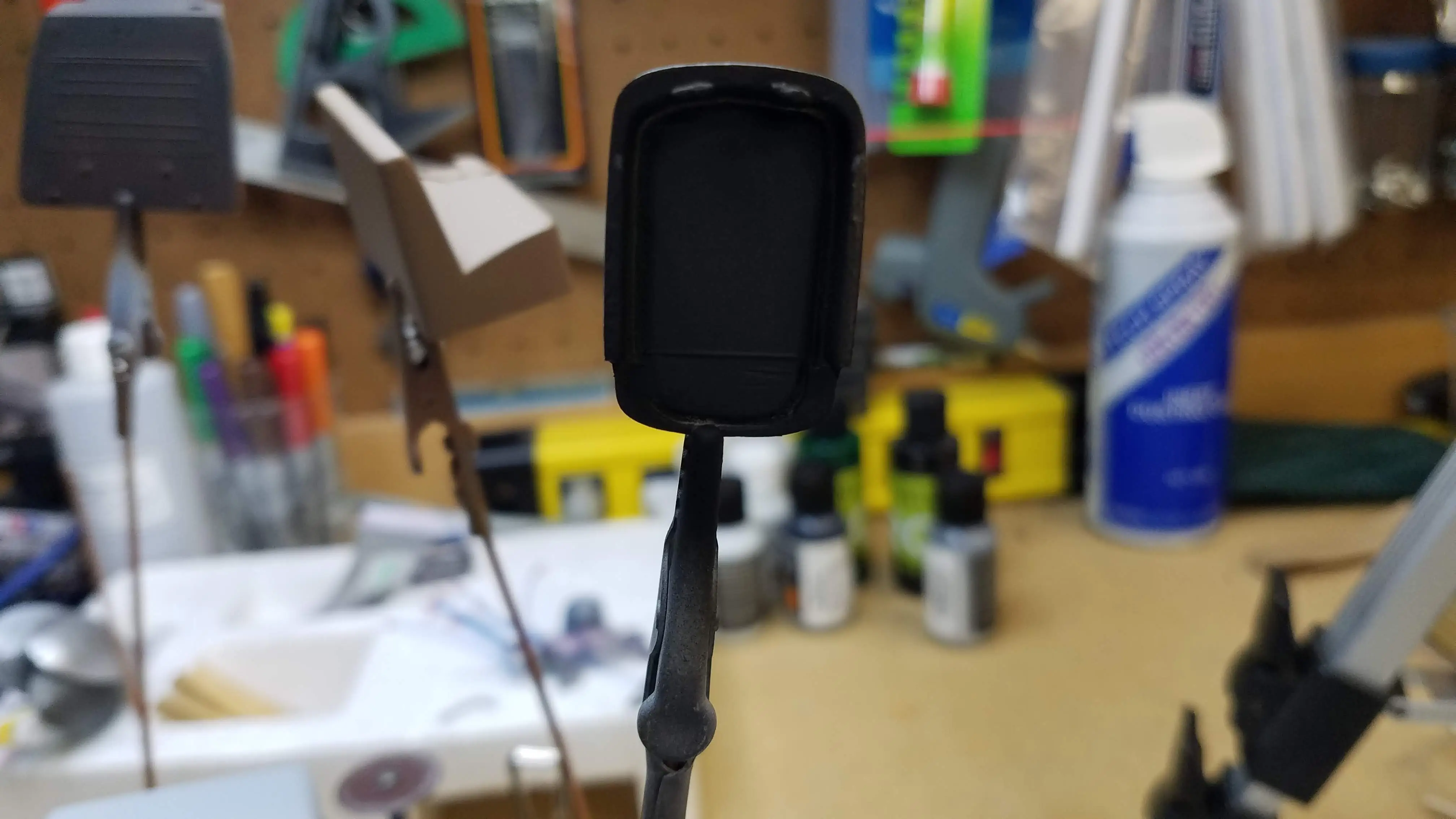
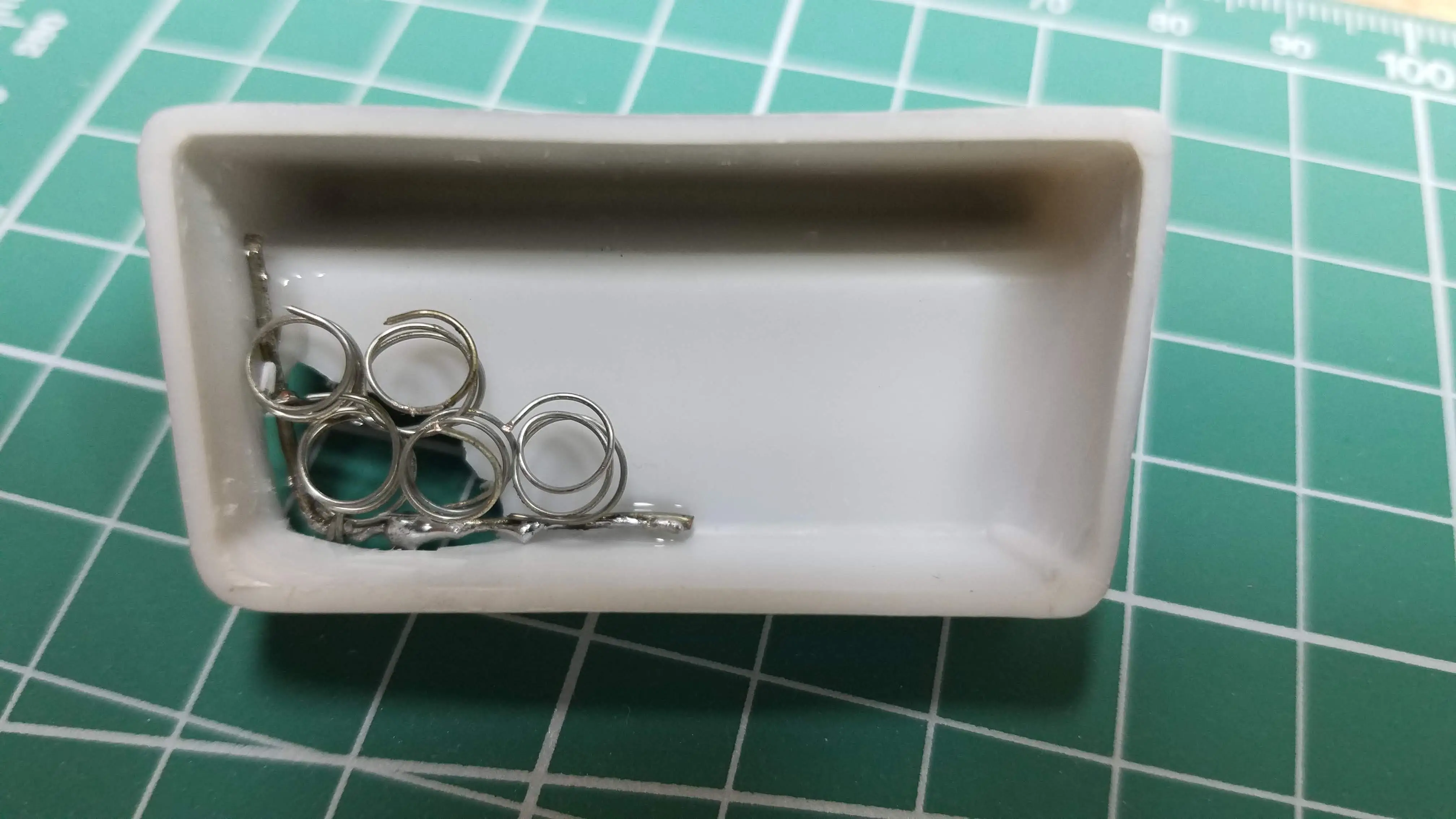 Making a torn seat with seat springs, bottom view
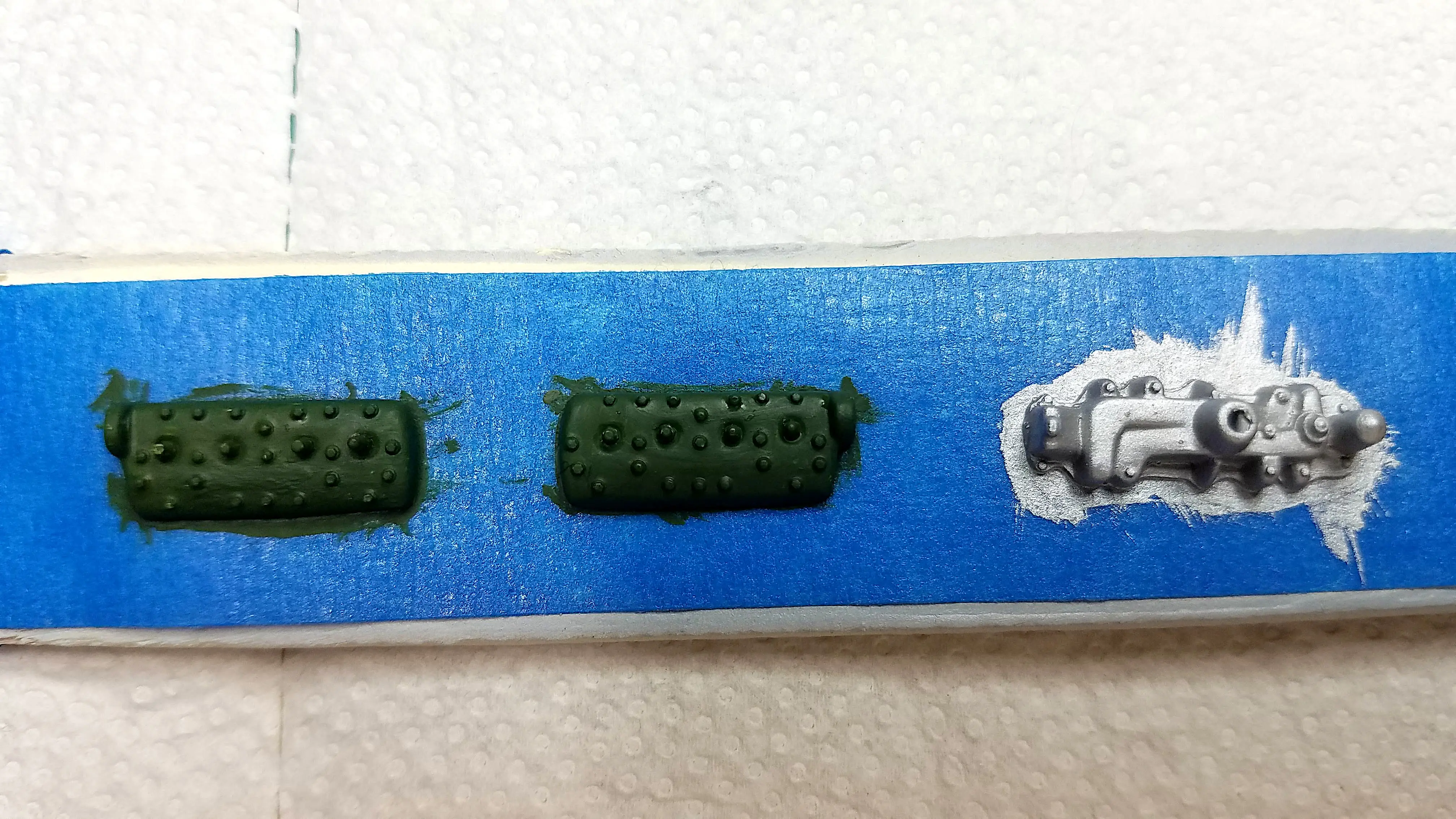 Heads and intake manifold painted
 Engine block and transmission housing
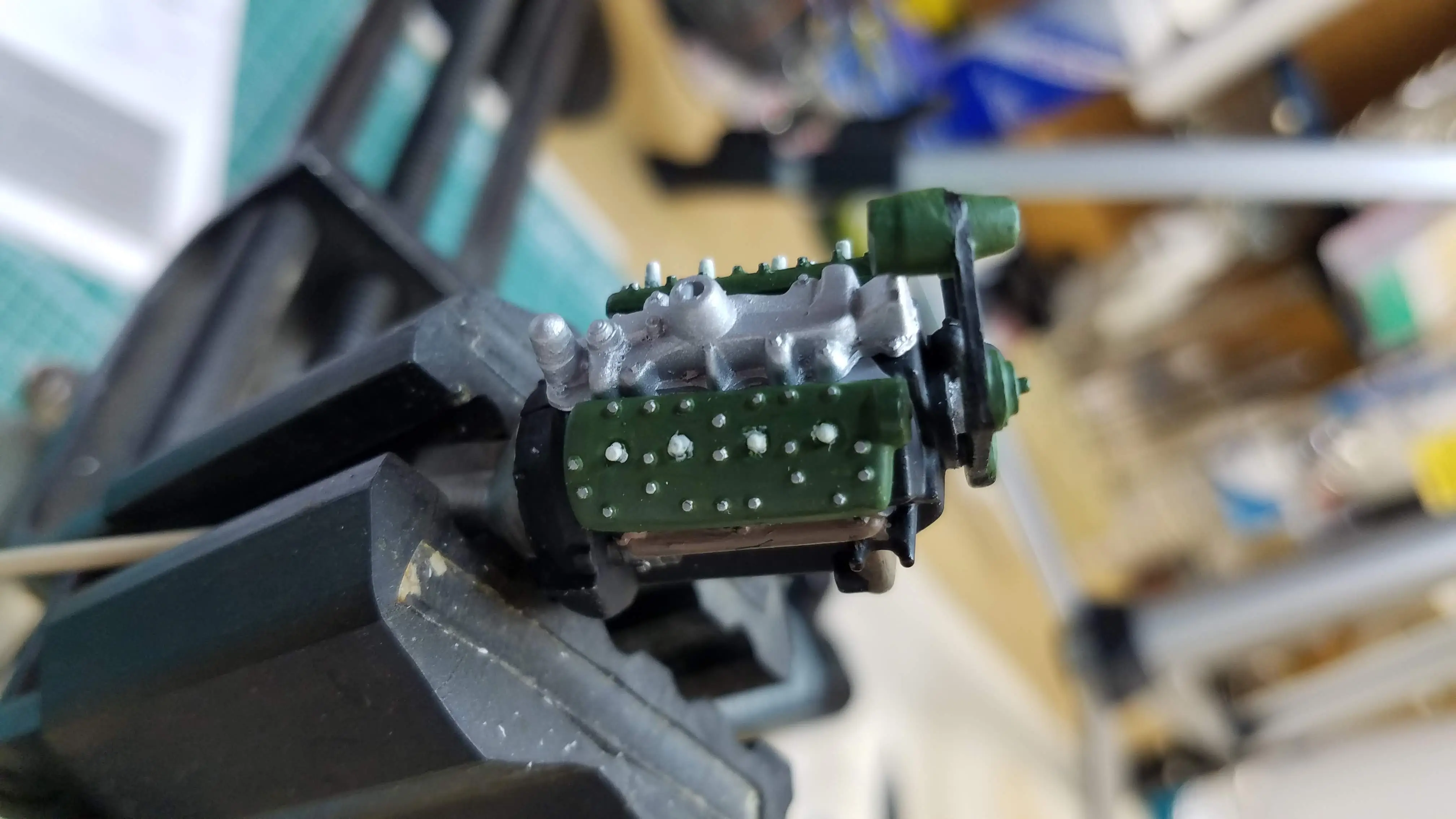
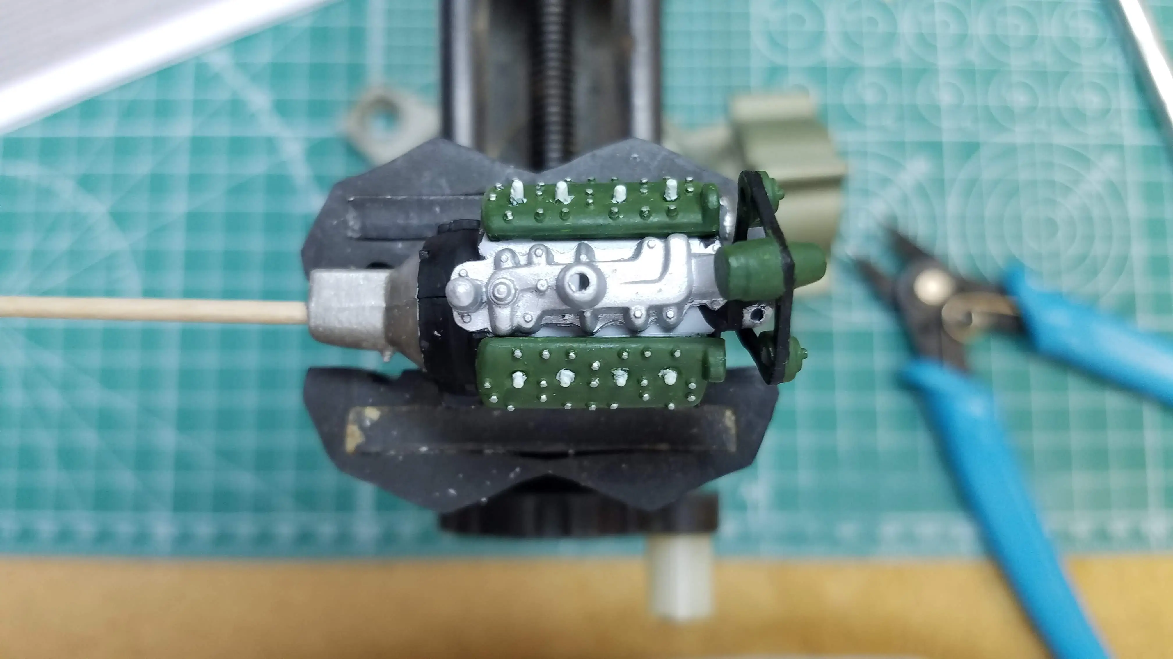
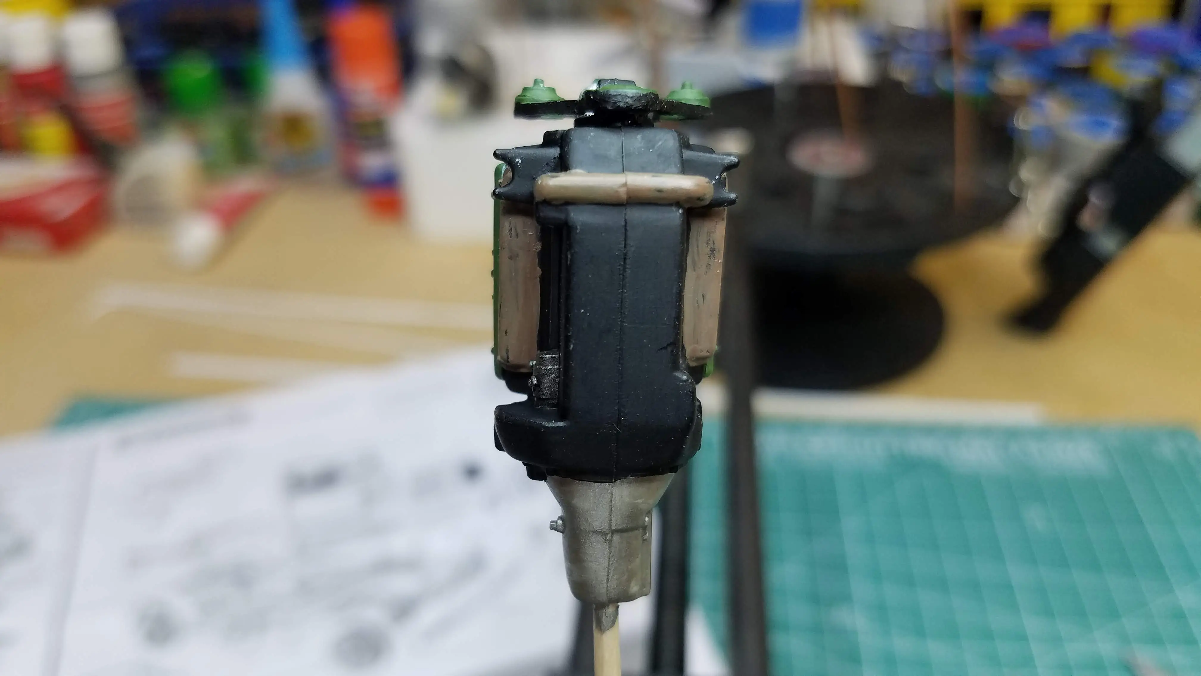
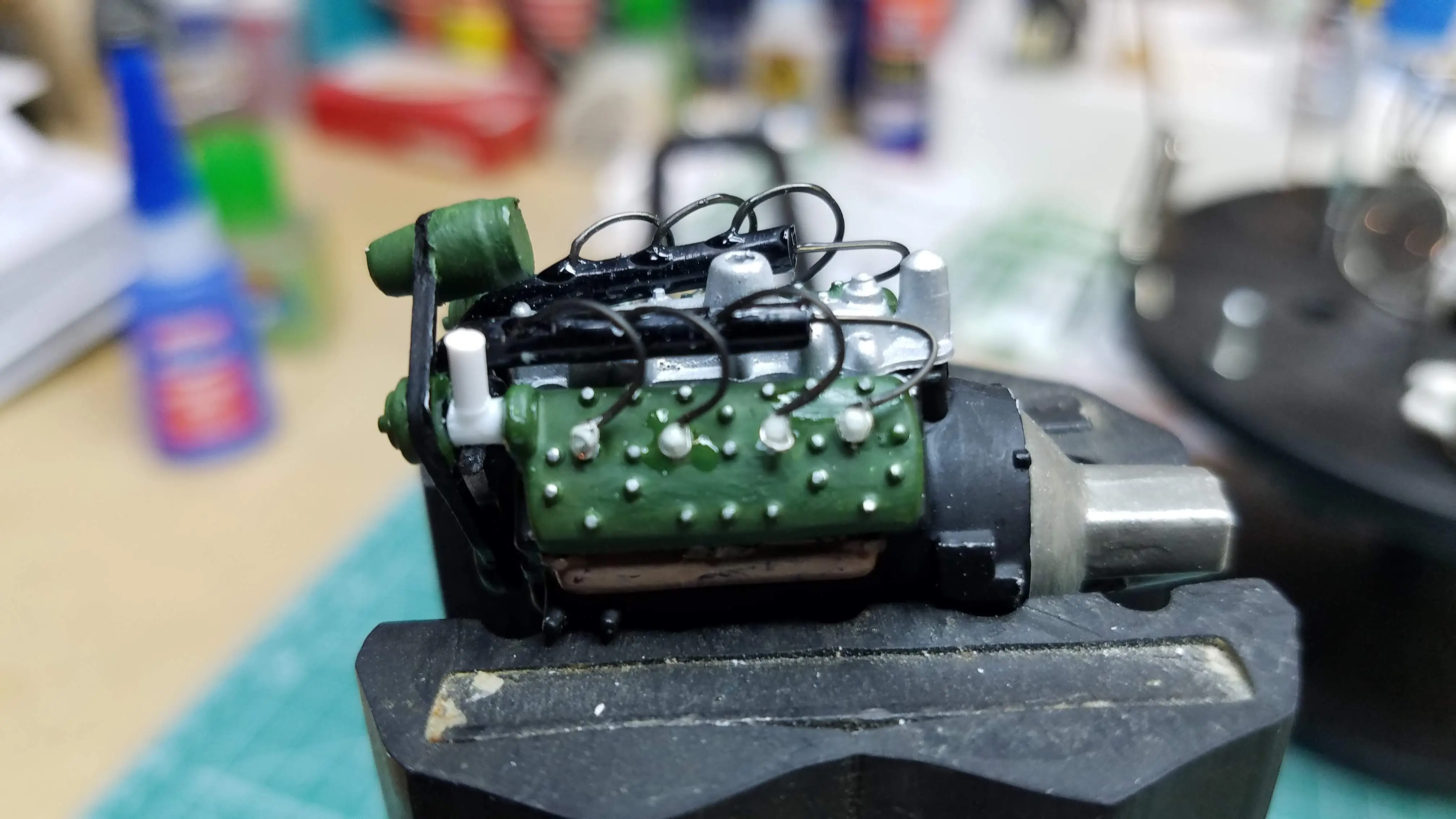
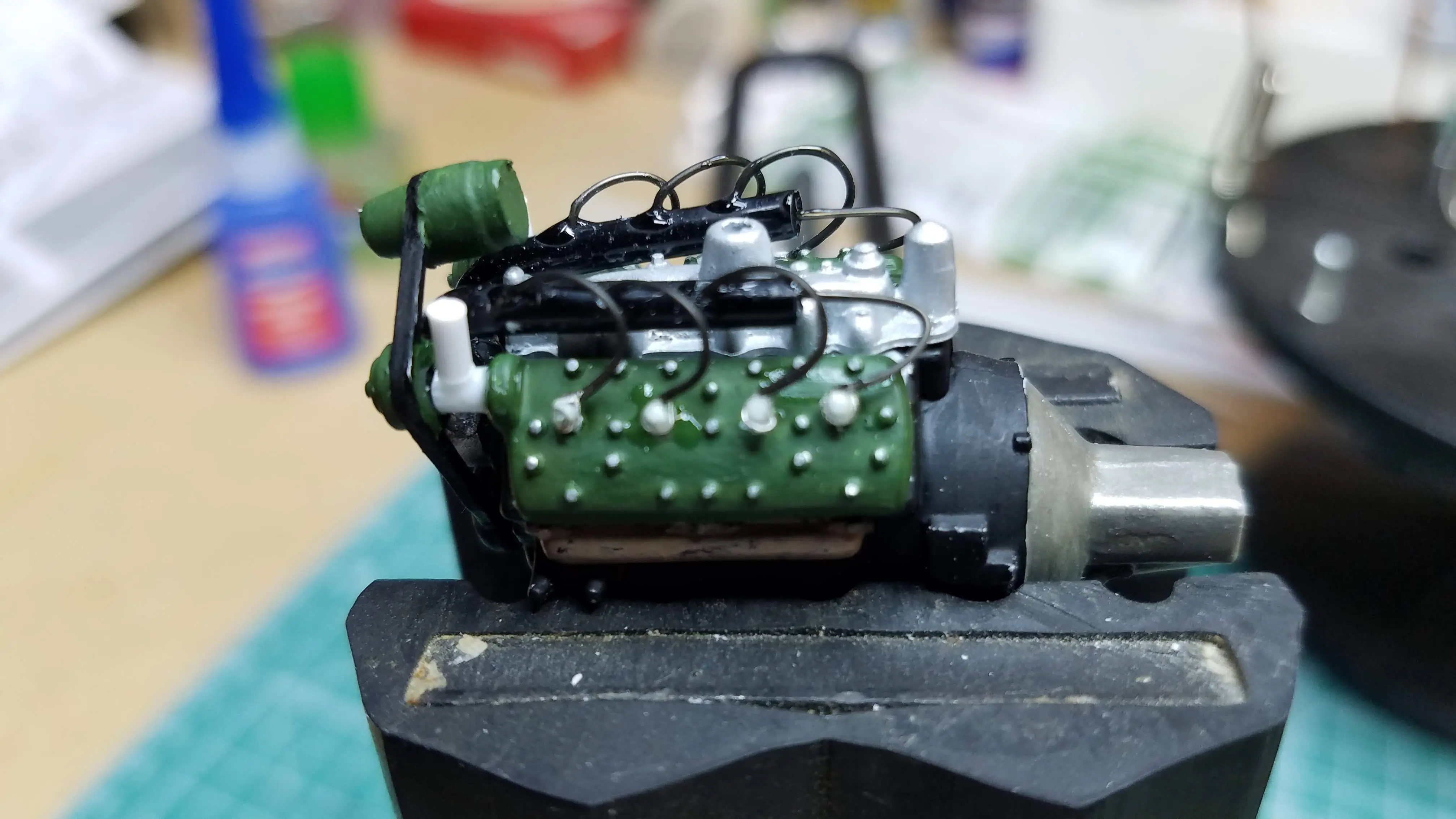
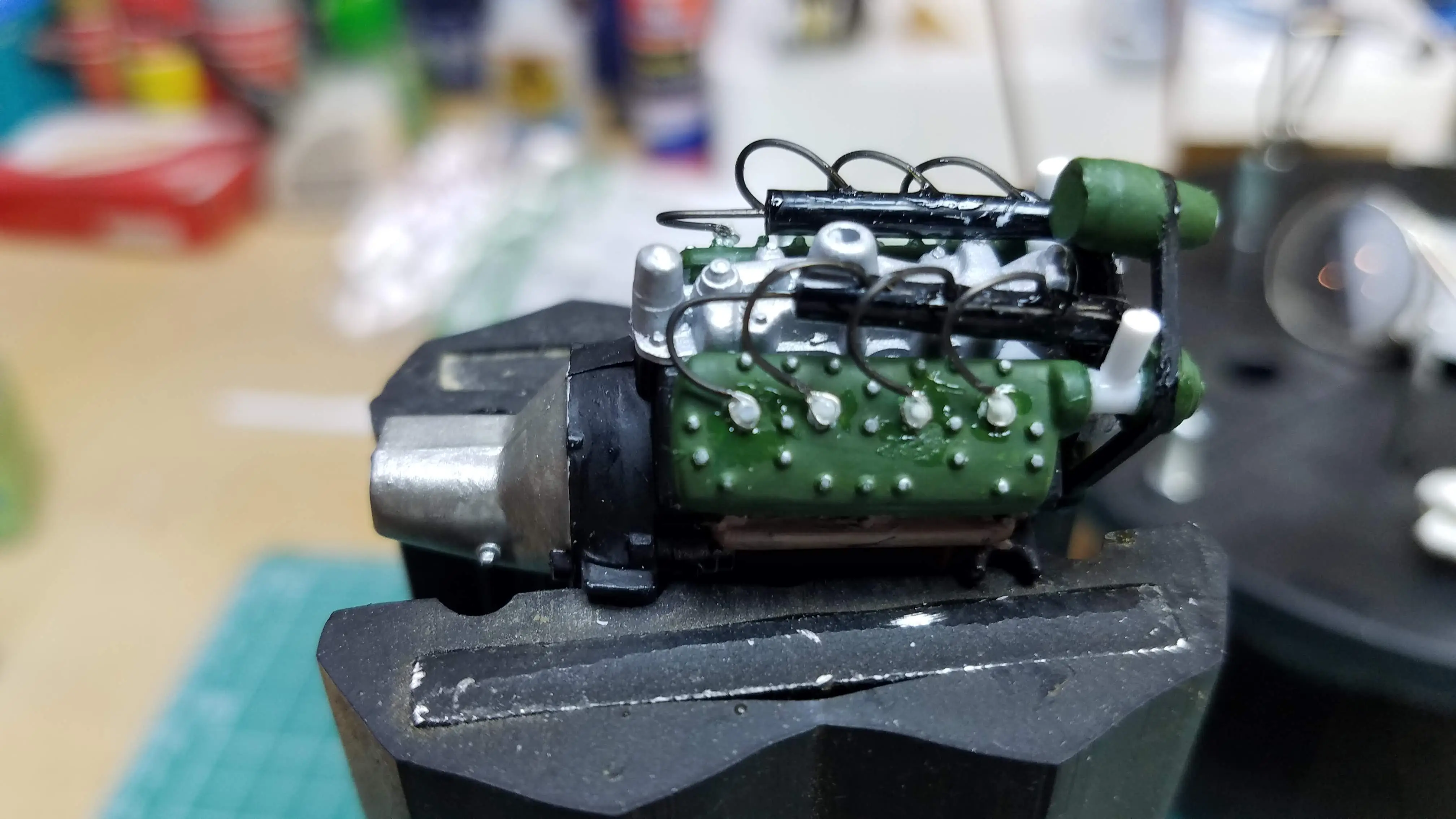
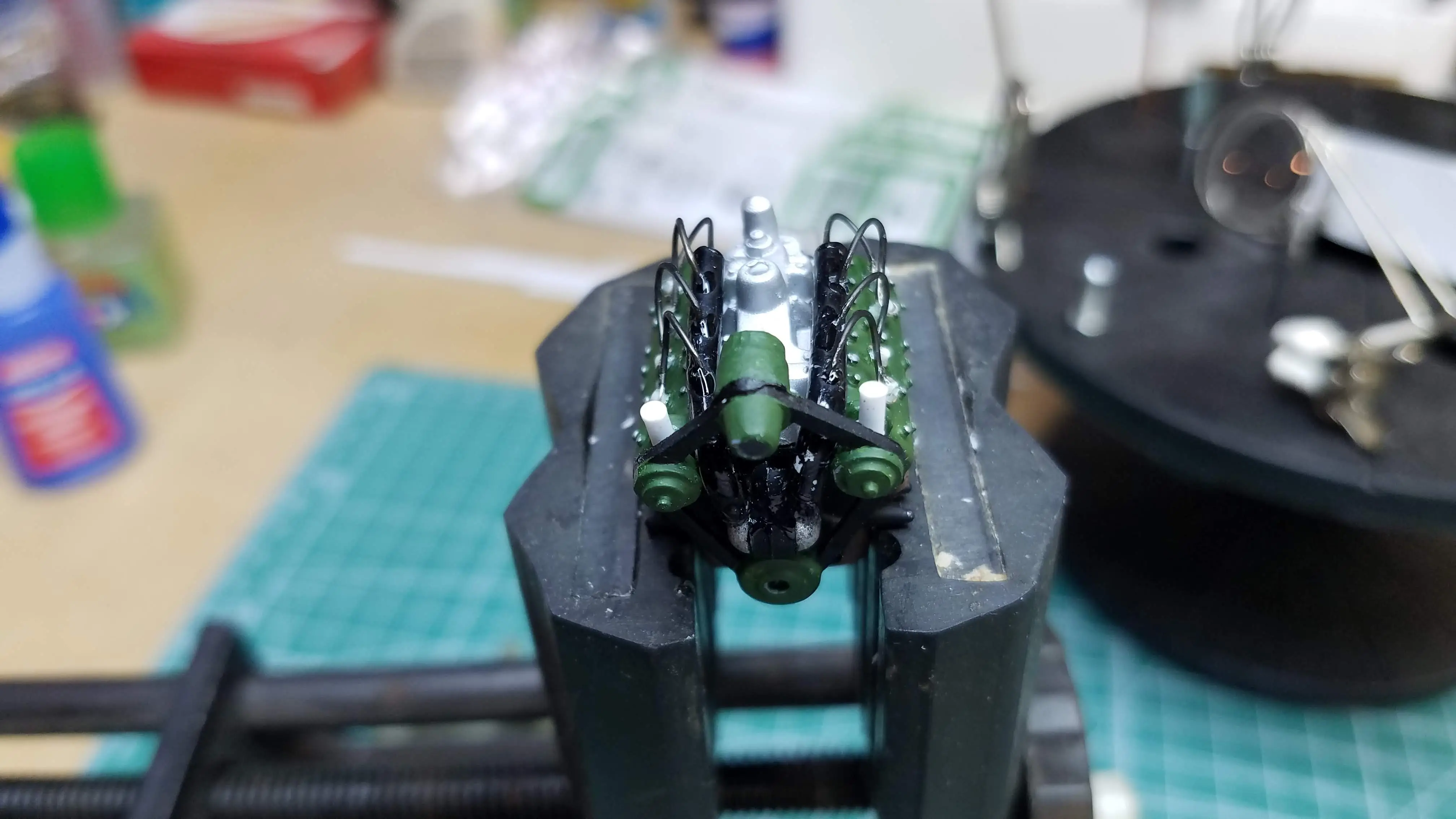
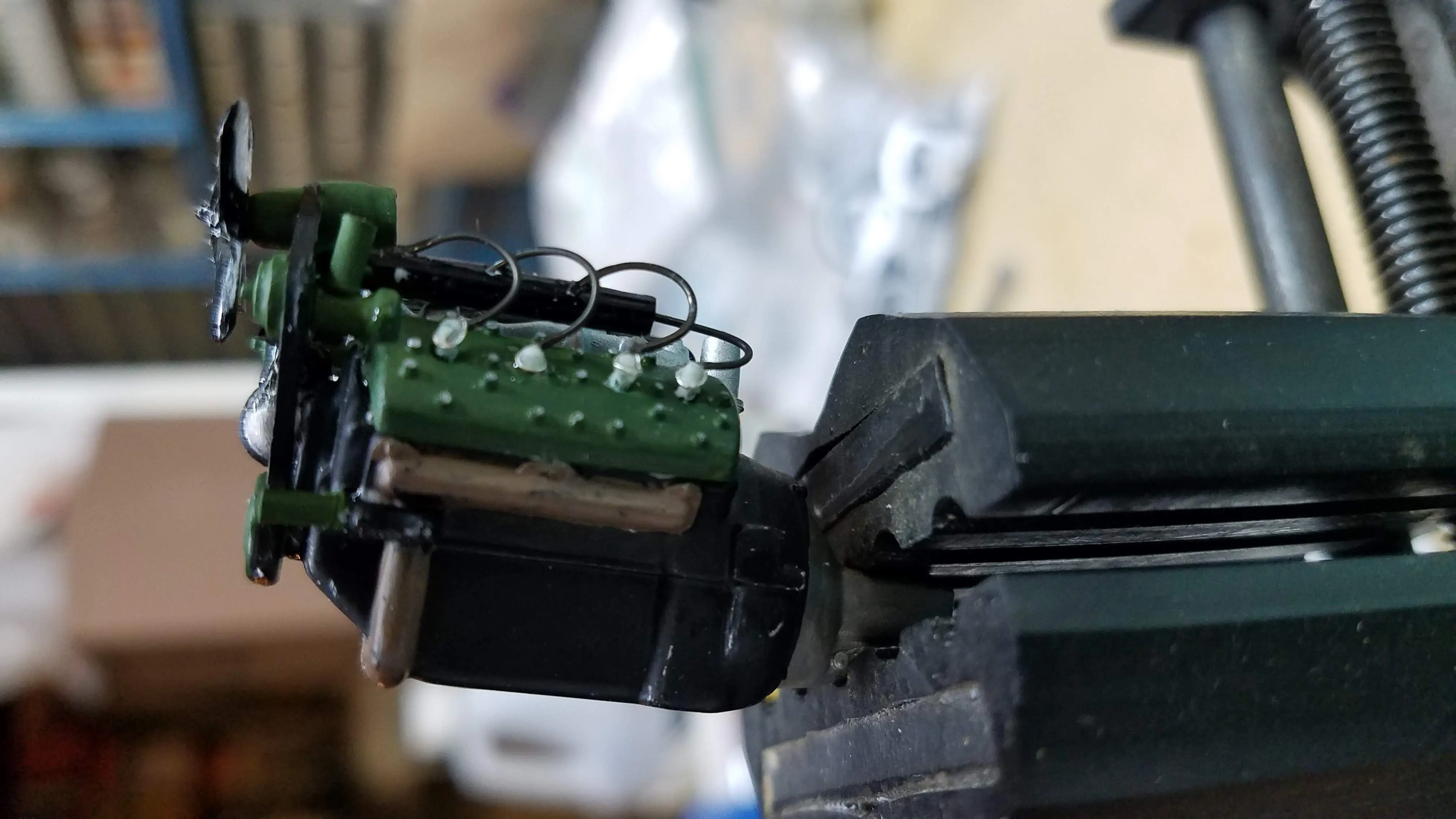
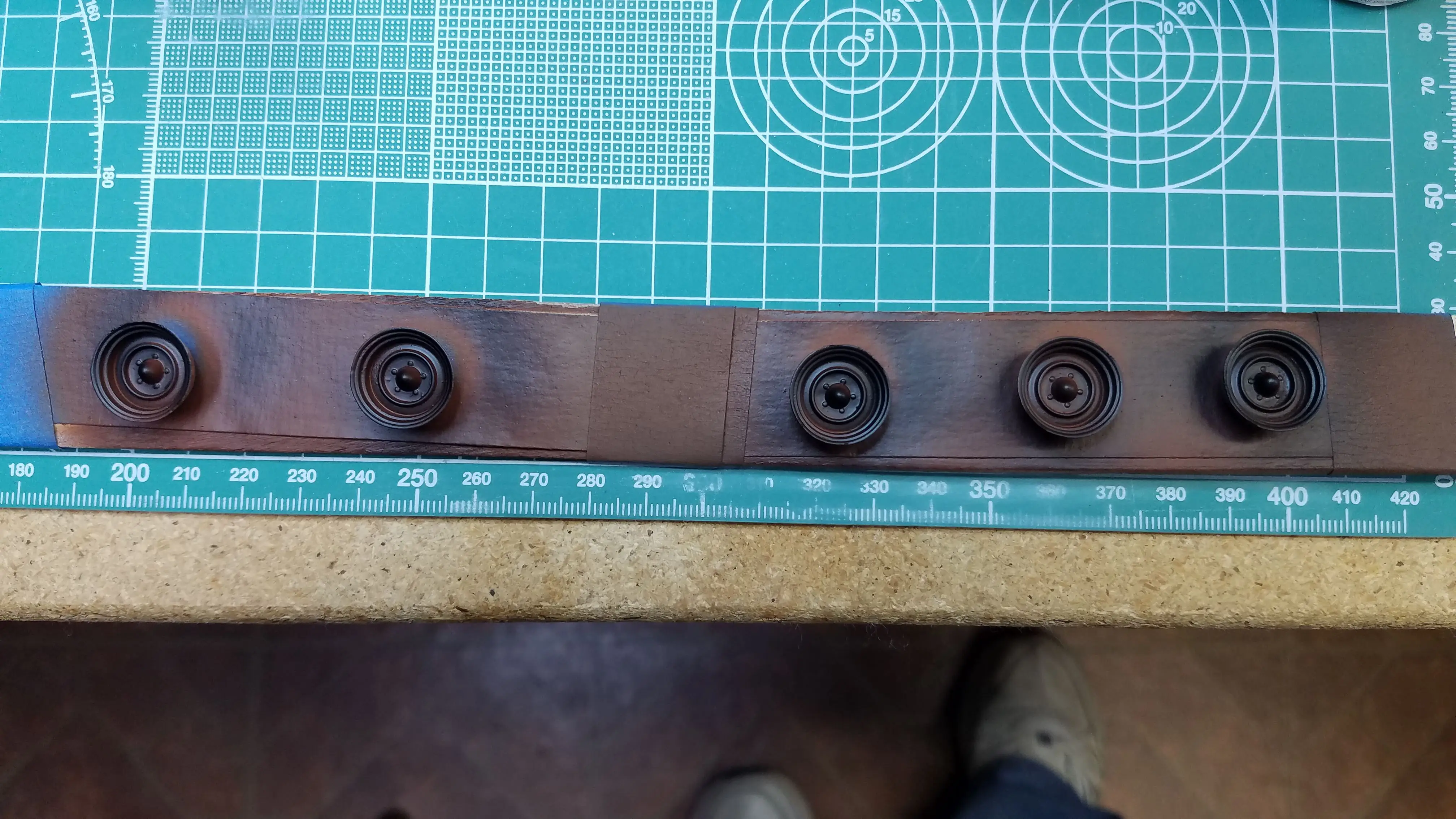
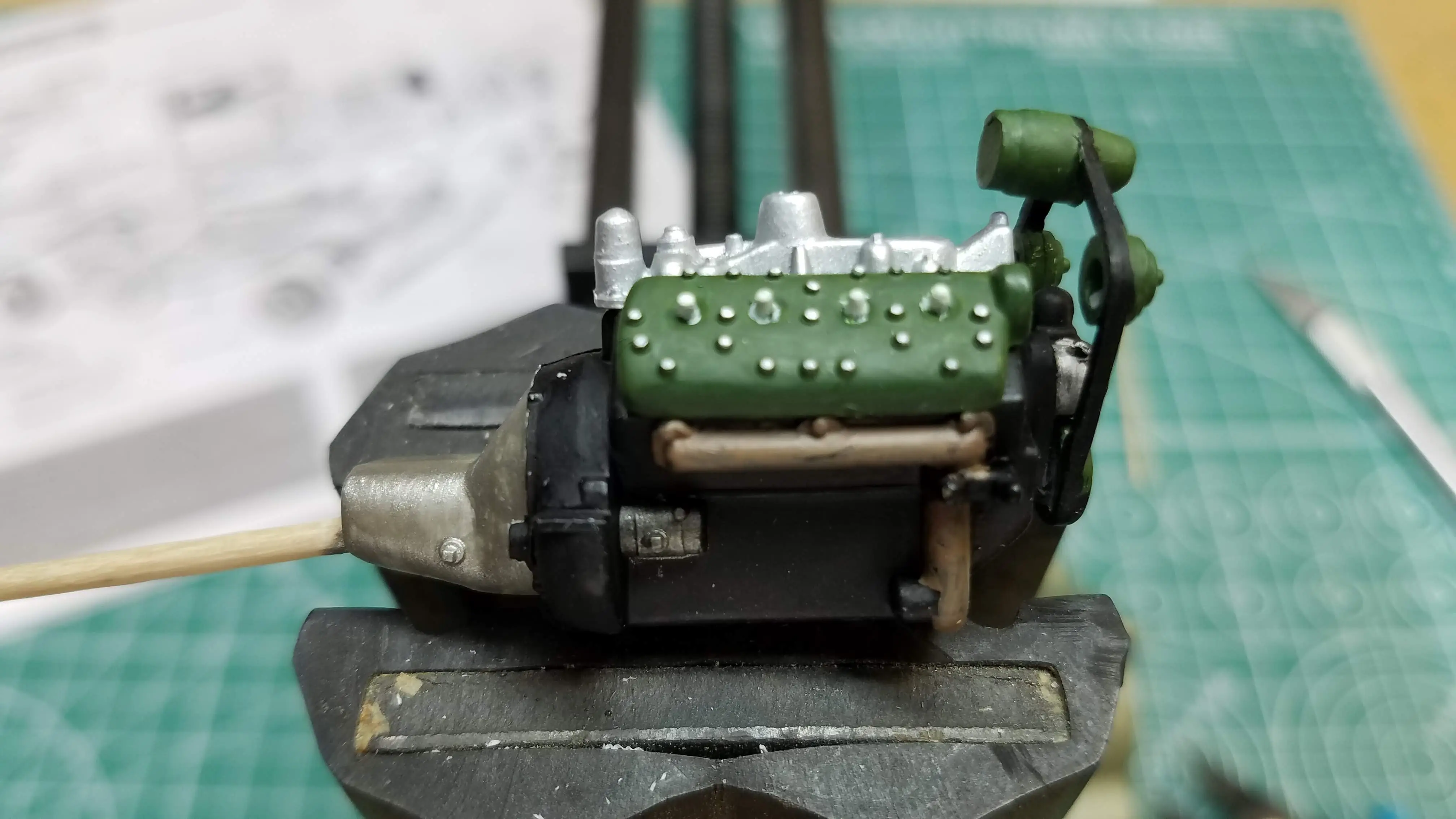 Starting to detailing the engine
 Starting to detailing the engine
 Starting to detailing the engine
 Starting to detailing the engine
 Starting to detailing the engine
 Starting to detailing the engine
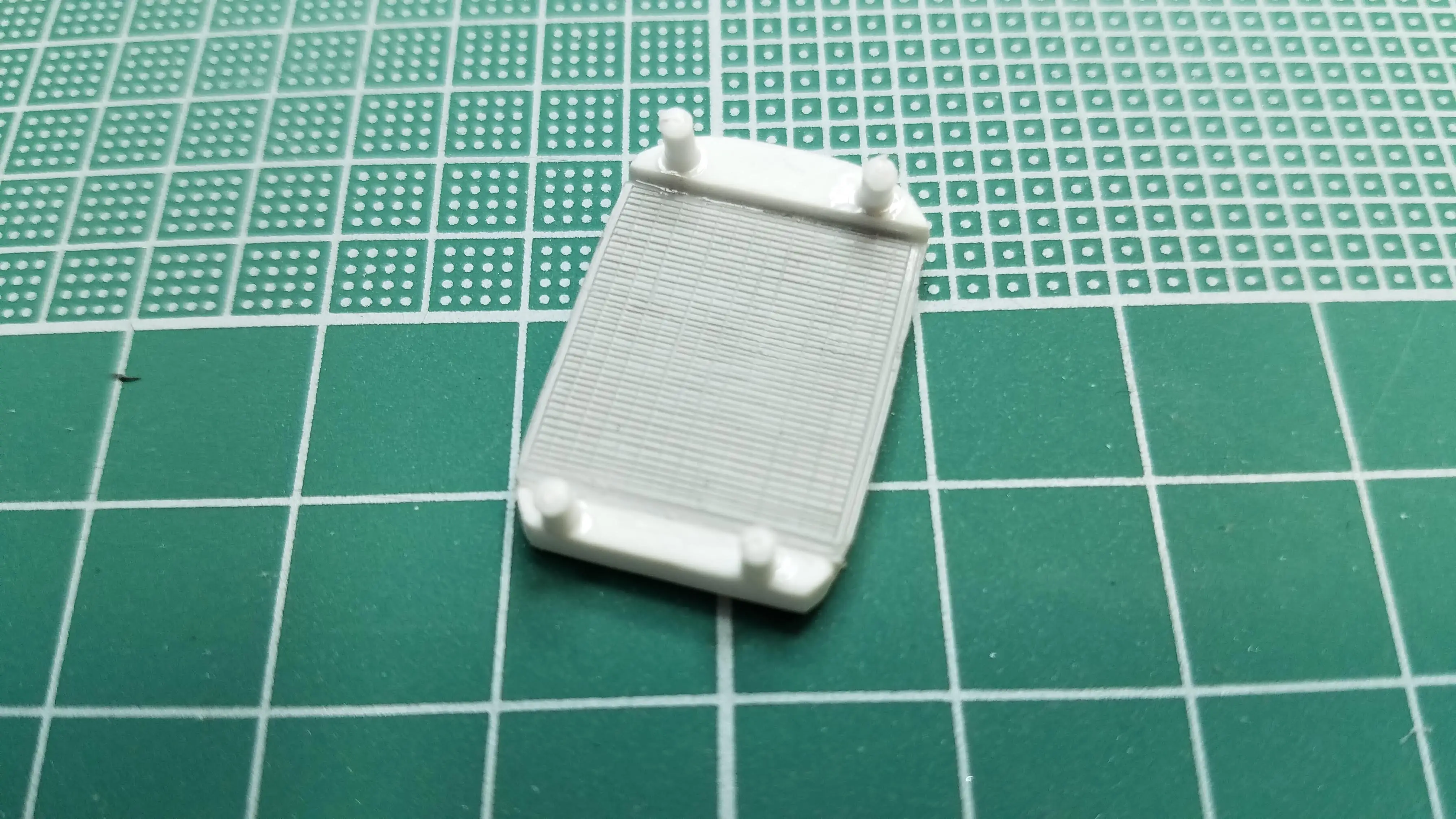
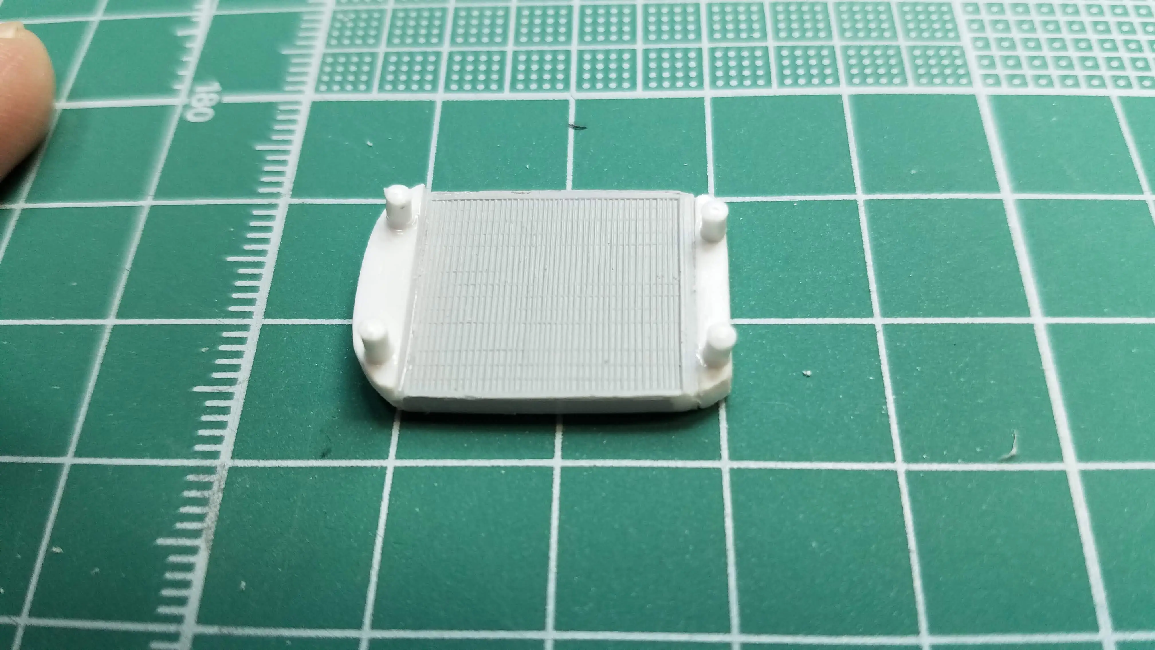
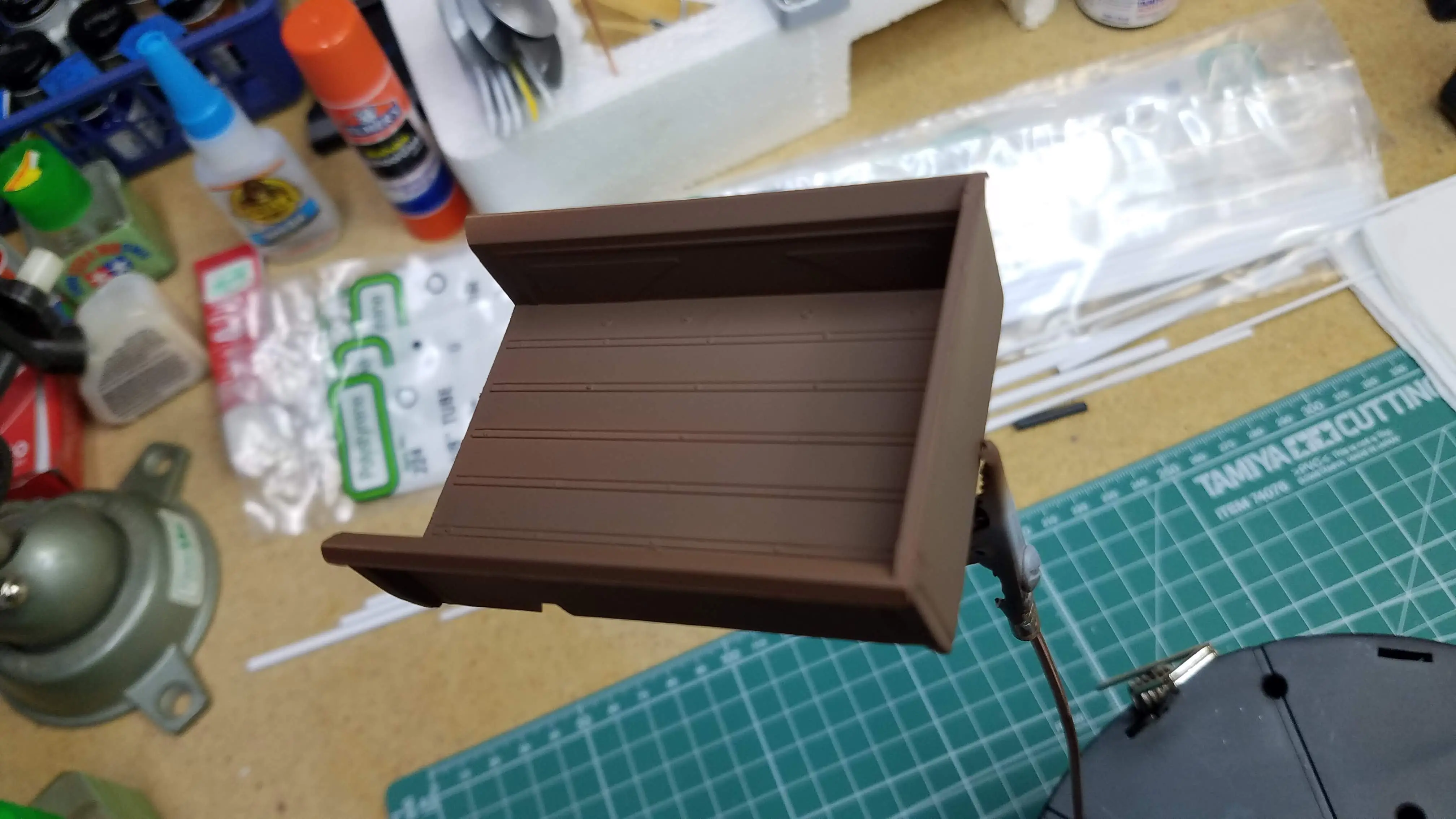
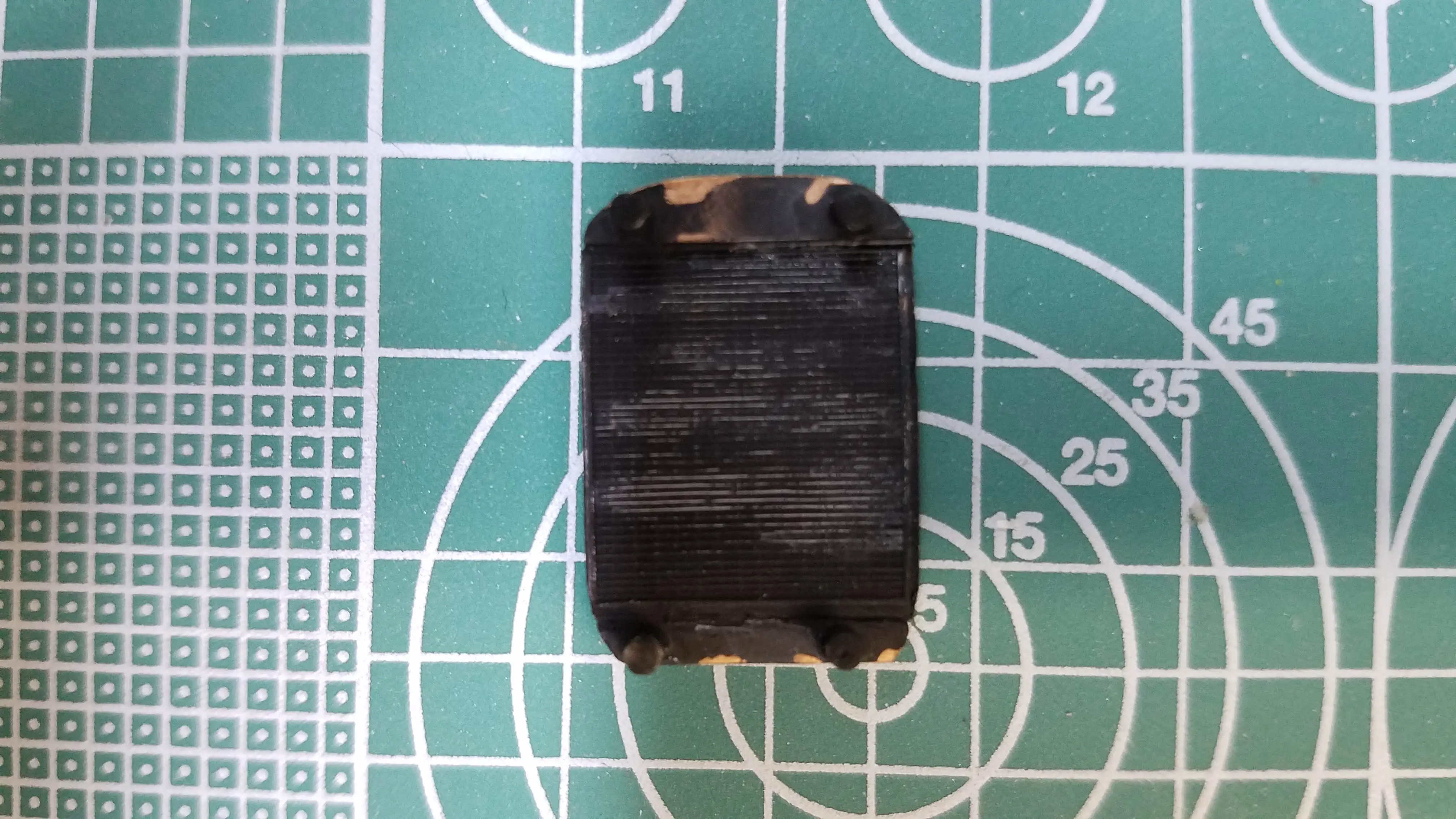
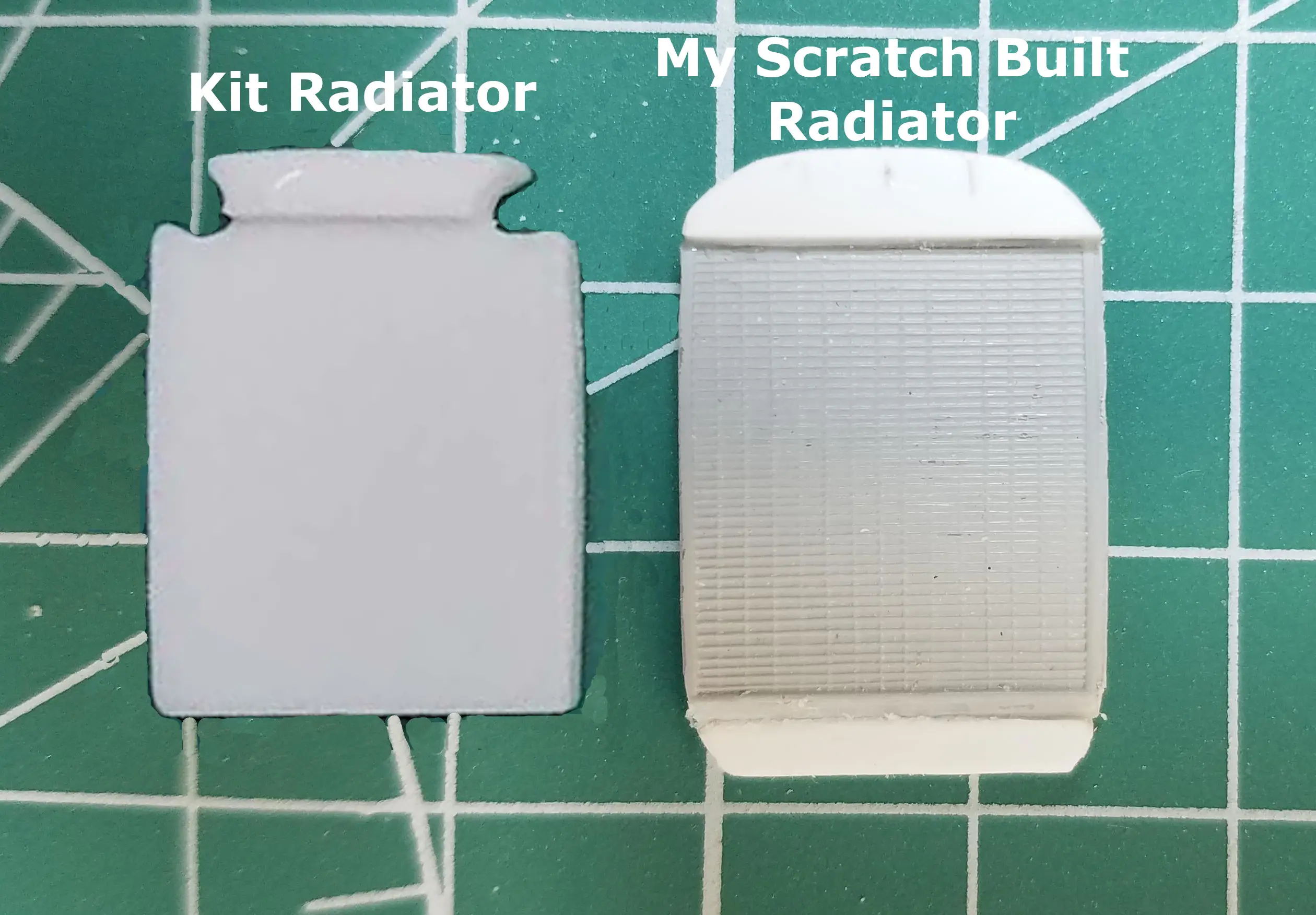 Scratch building a radiator
 Scratch building a radiator
 Scratch building a radiator
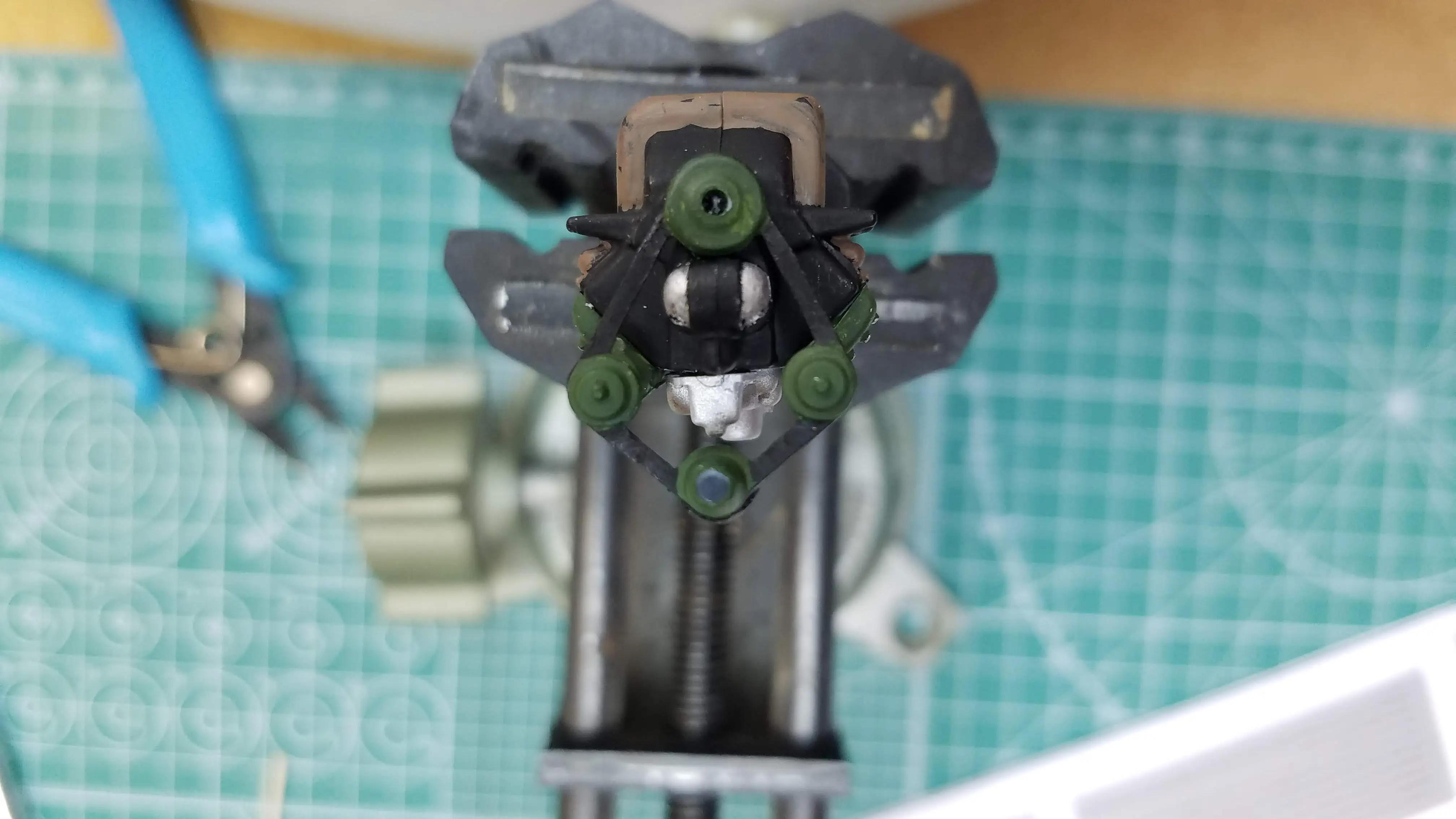
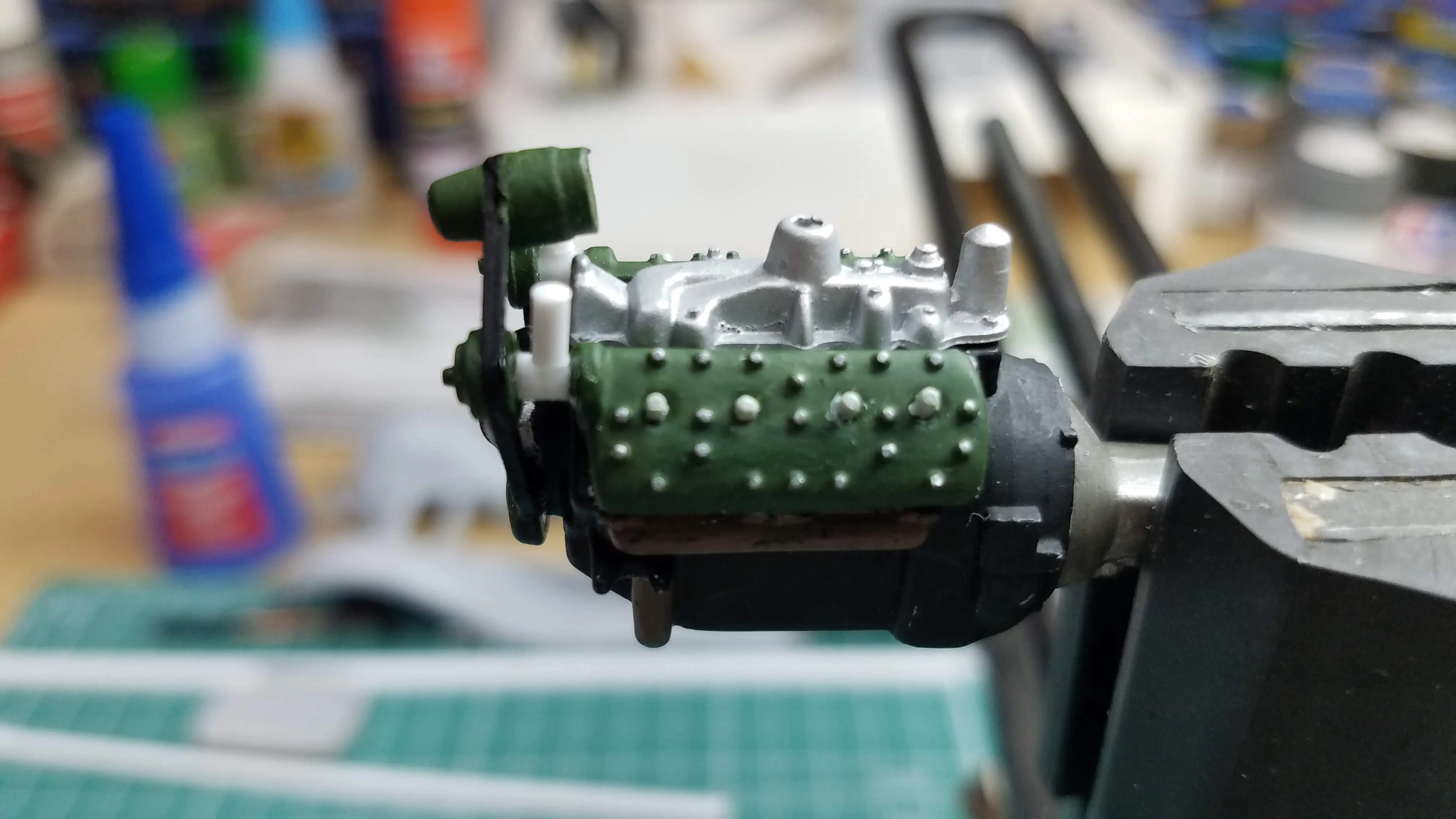 Adding radiator hose couplings to the engine
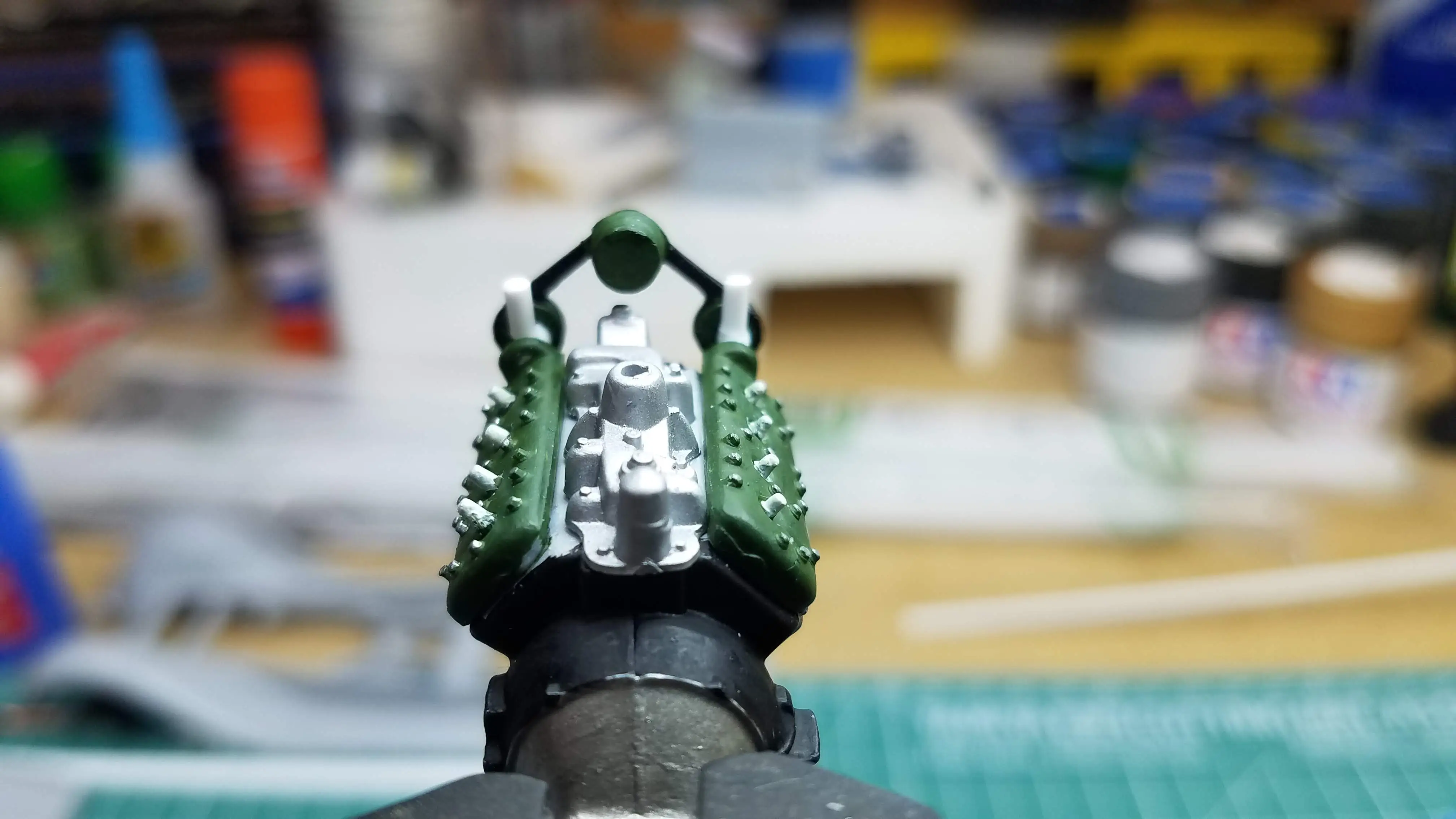 Adding radiator hose couplings to the engine
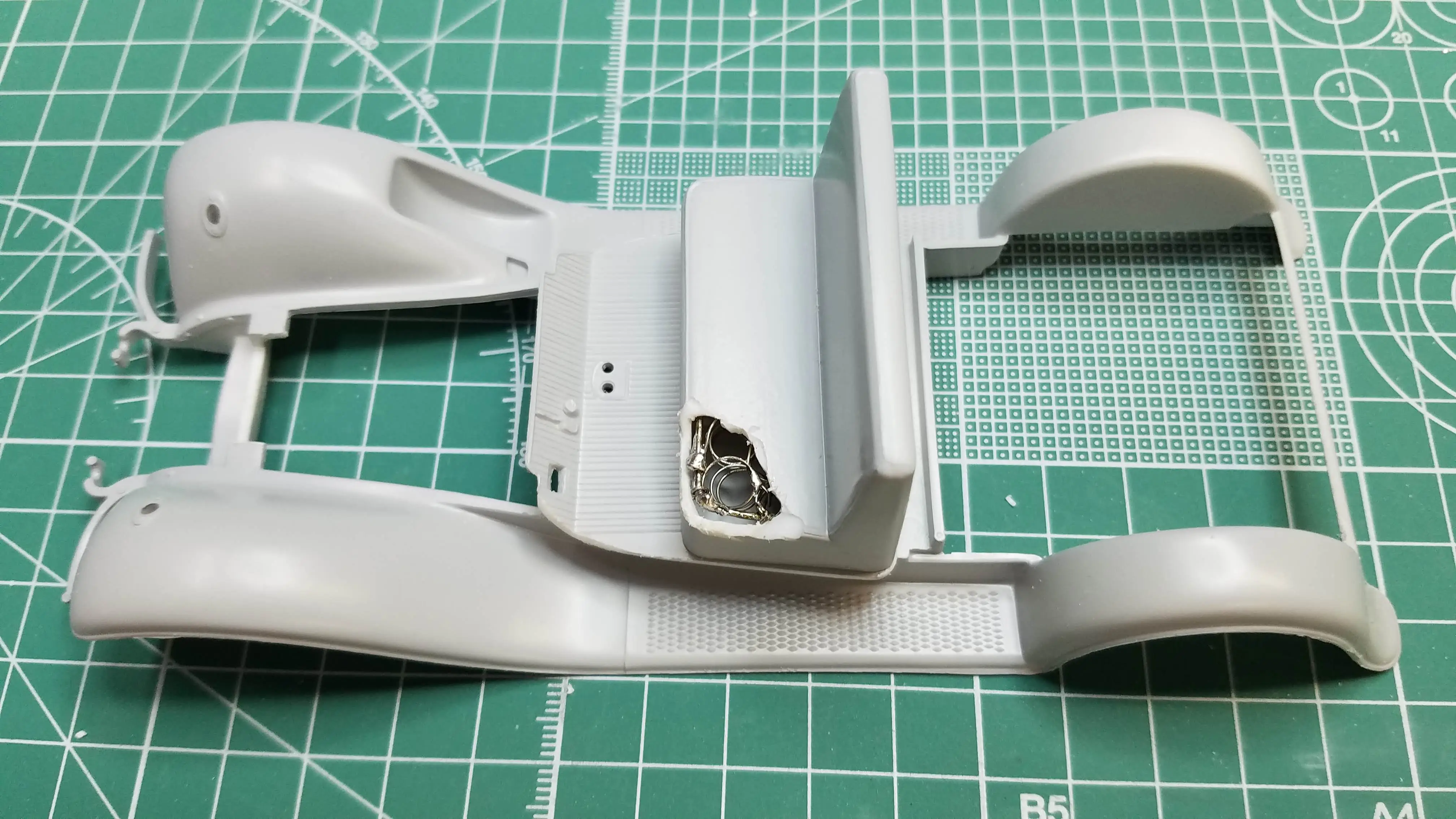
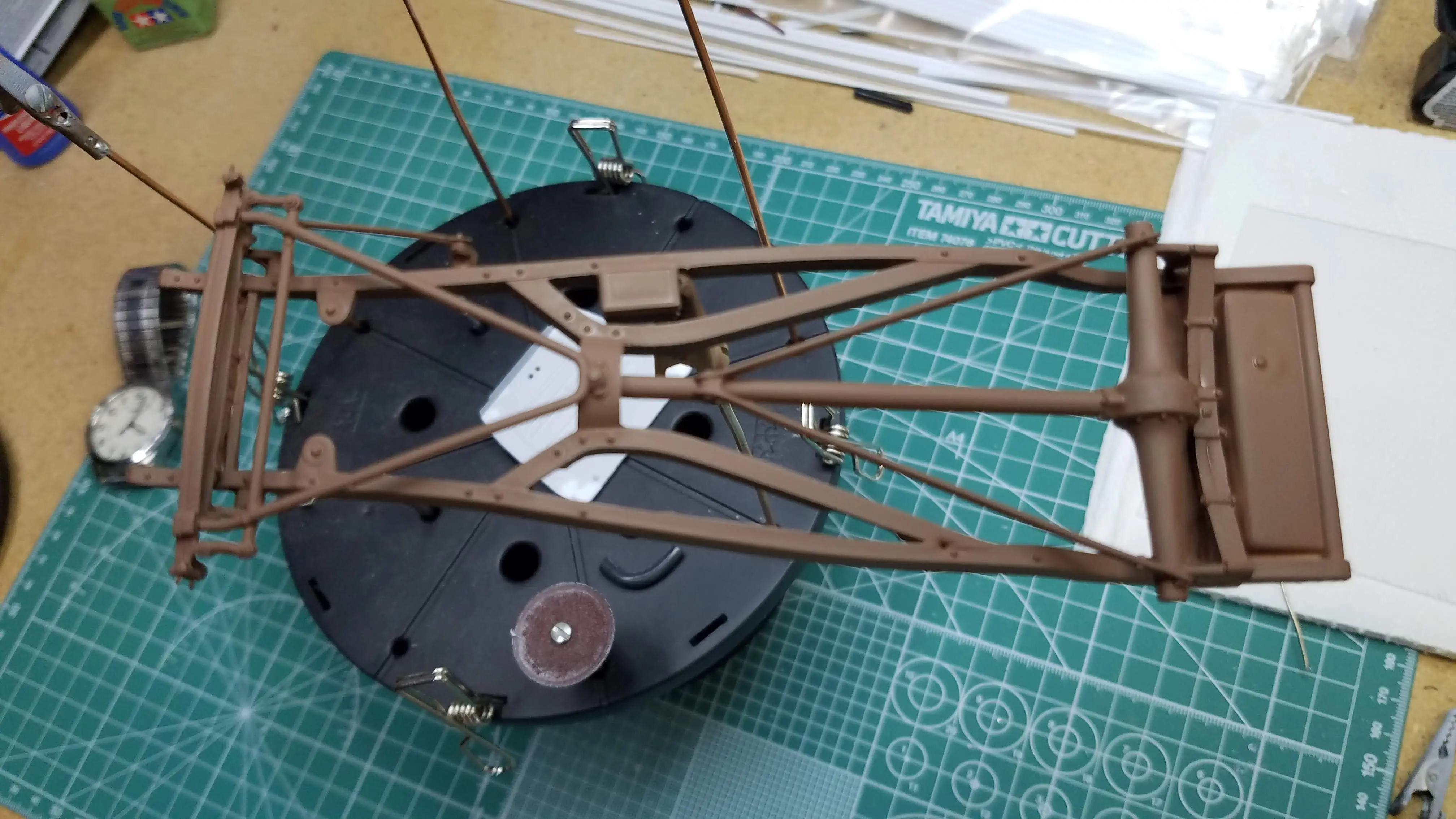
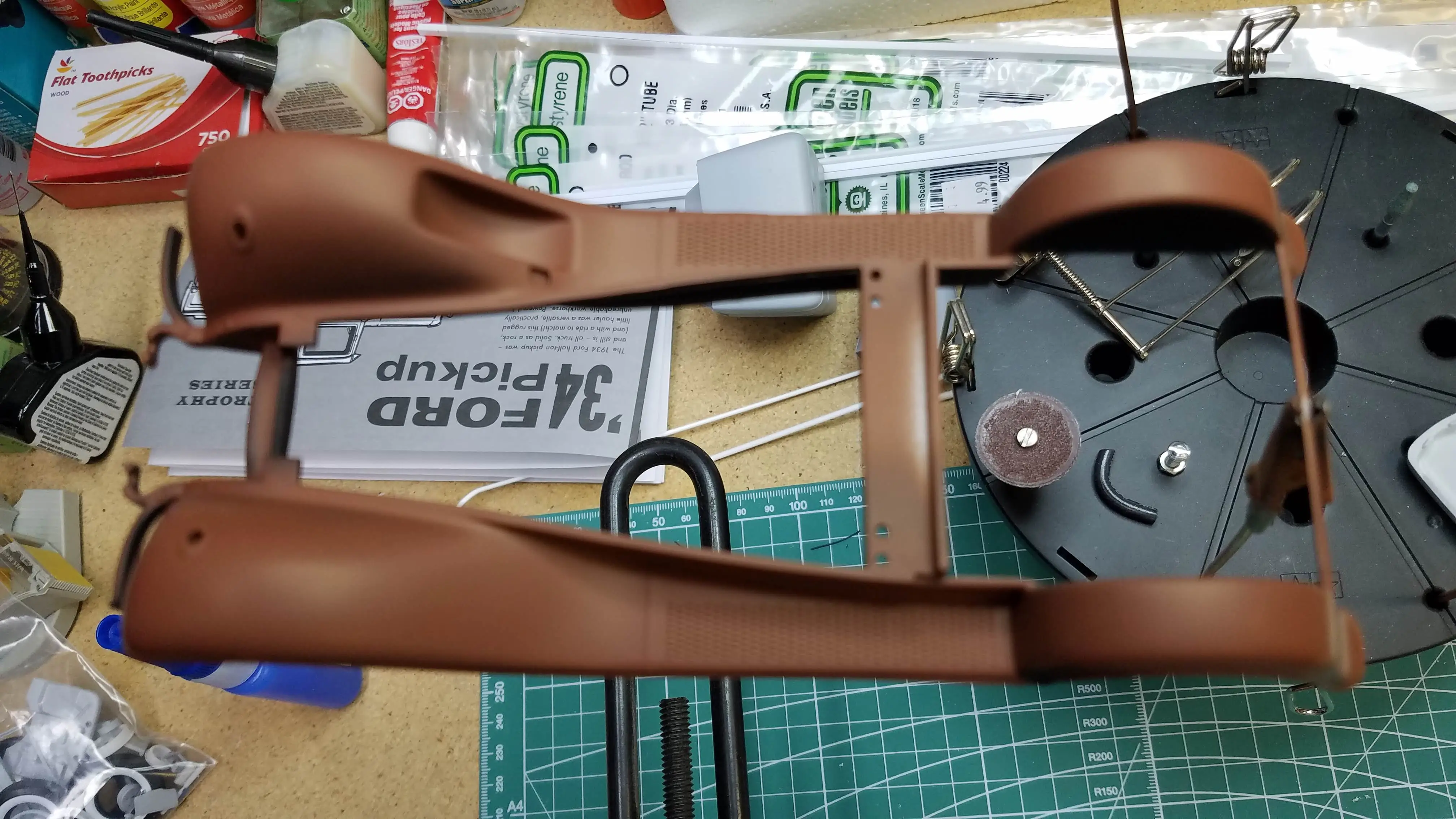
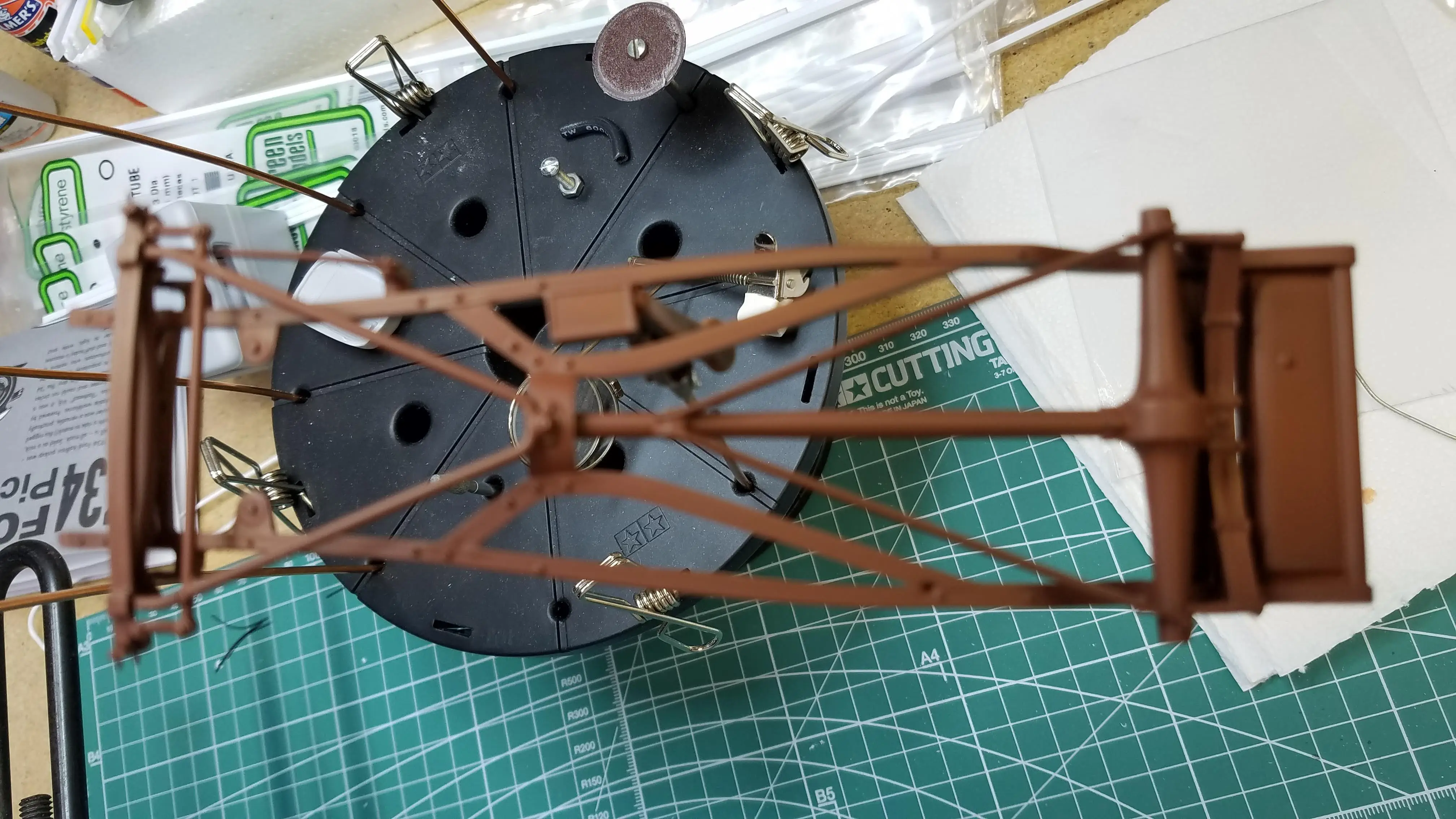
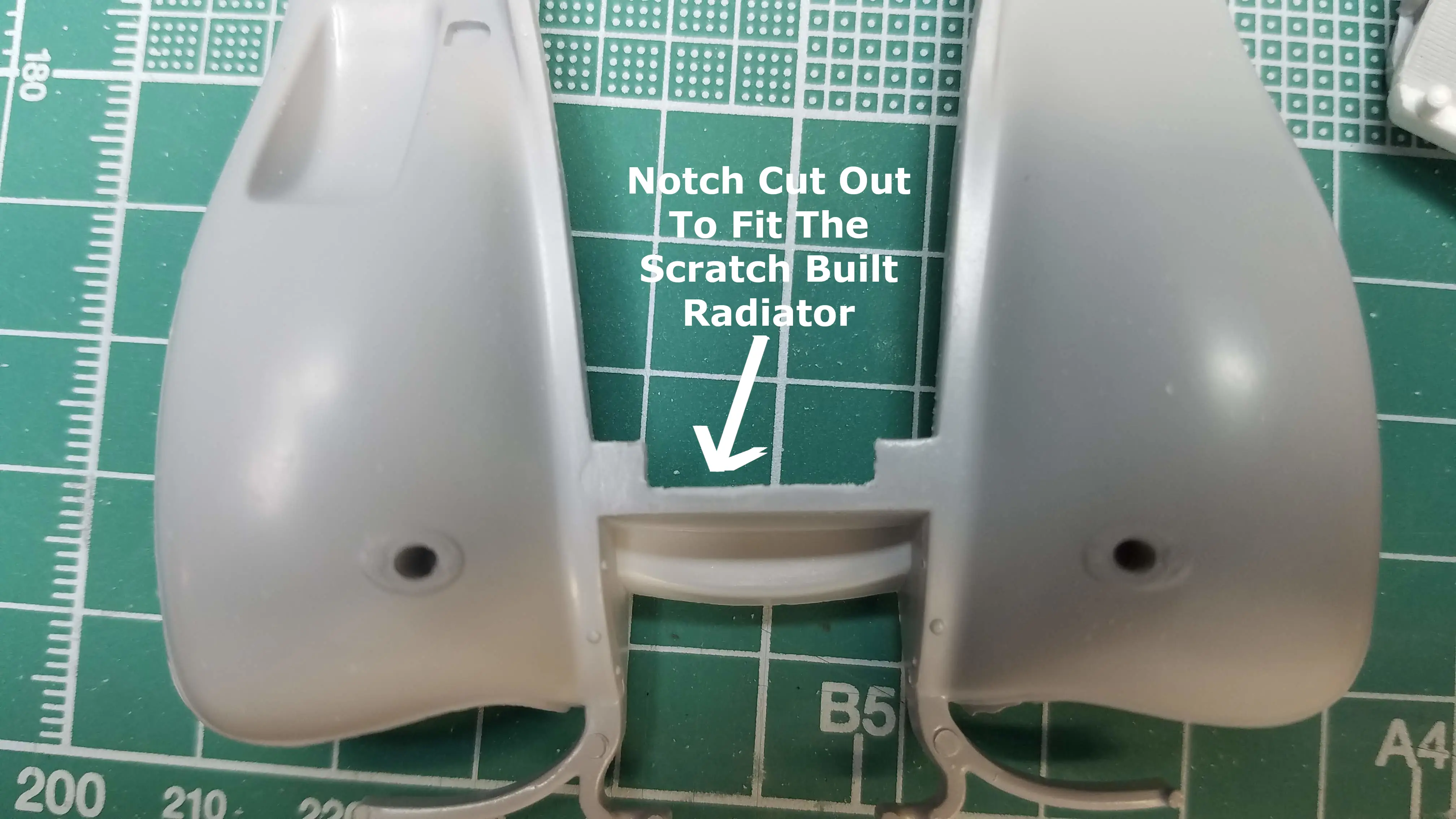 Frame modification to fit the scratch built radiator
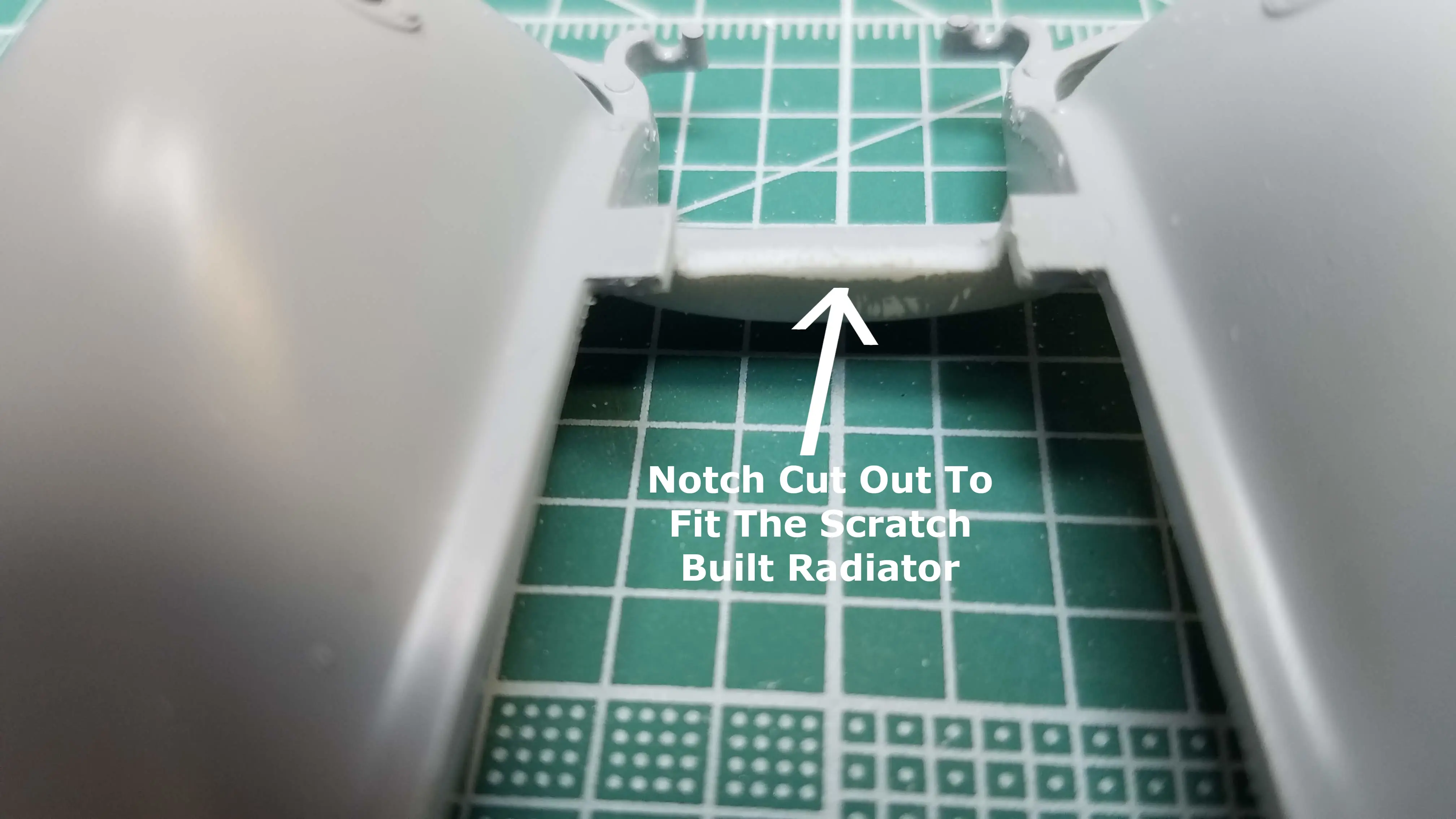 Frame modification to fit the scratch built radiator
 Fitting the scratch built radiator
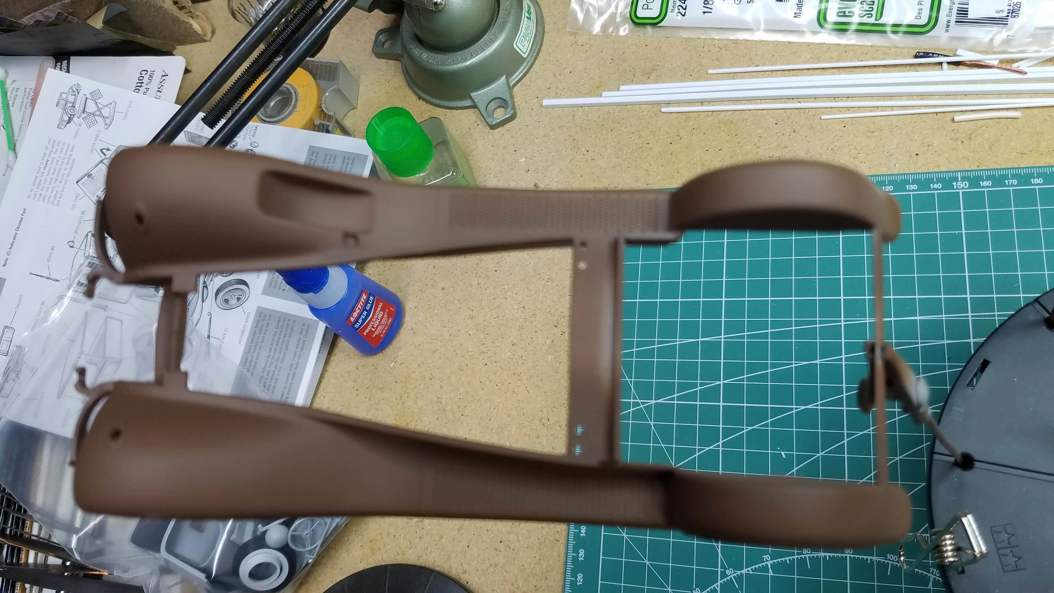
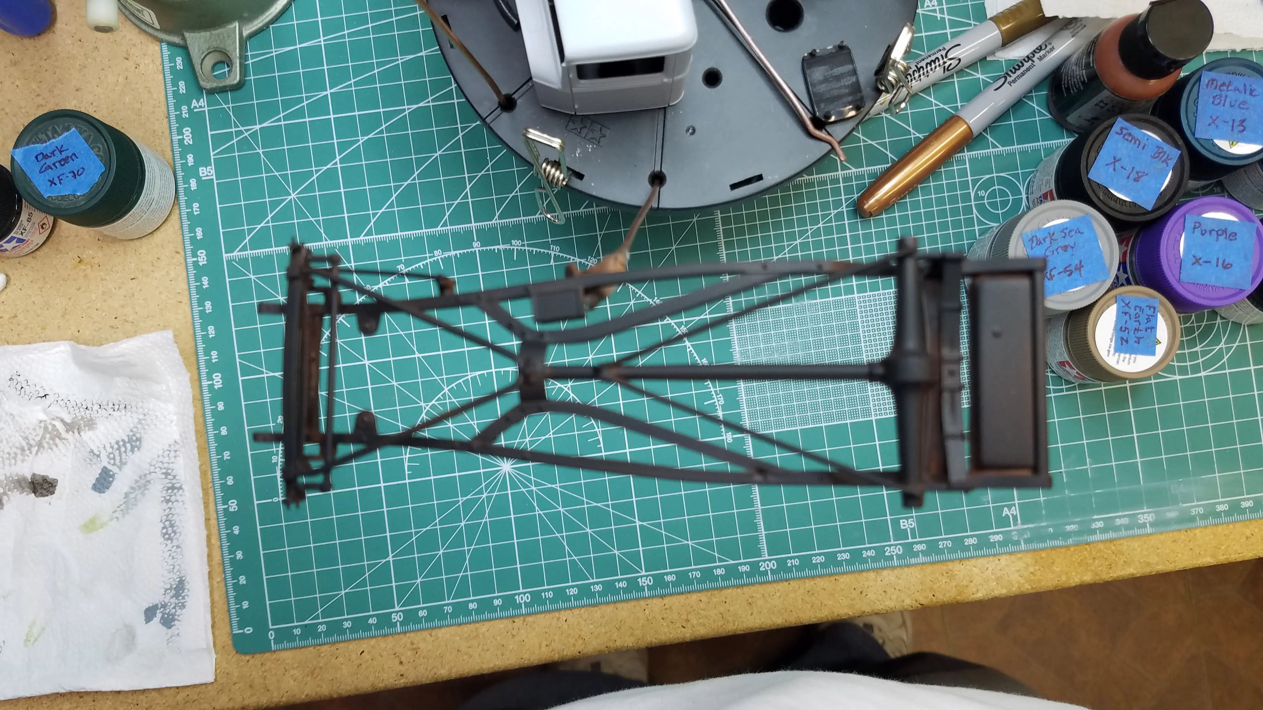
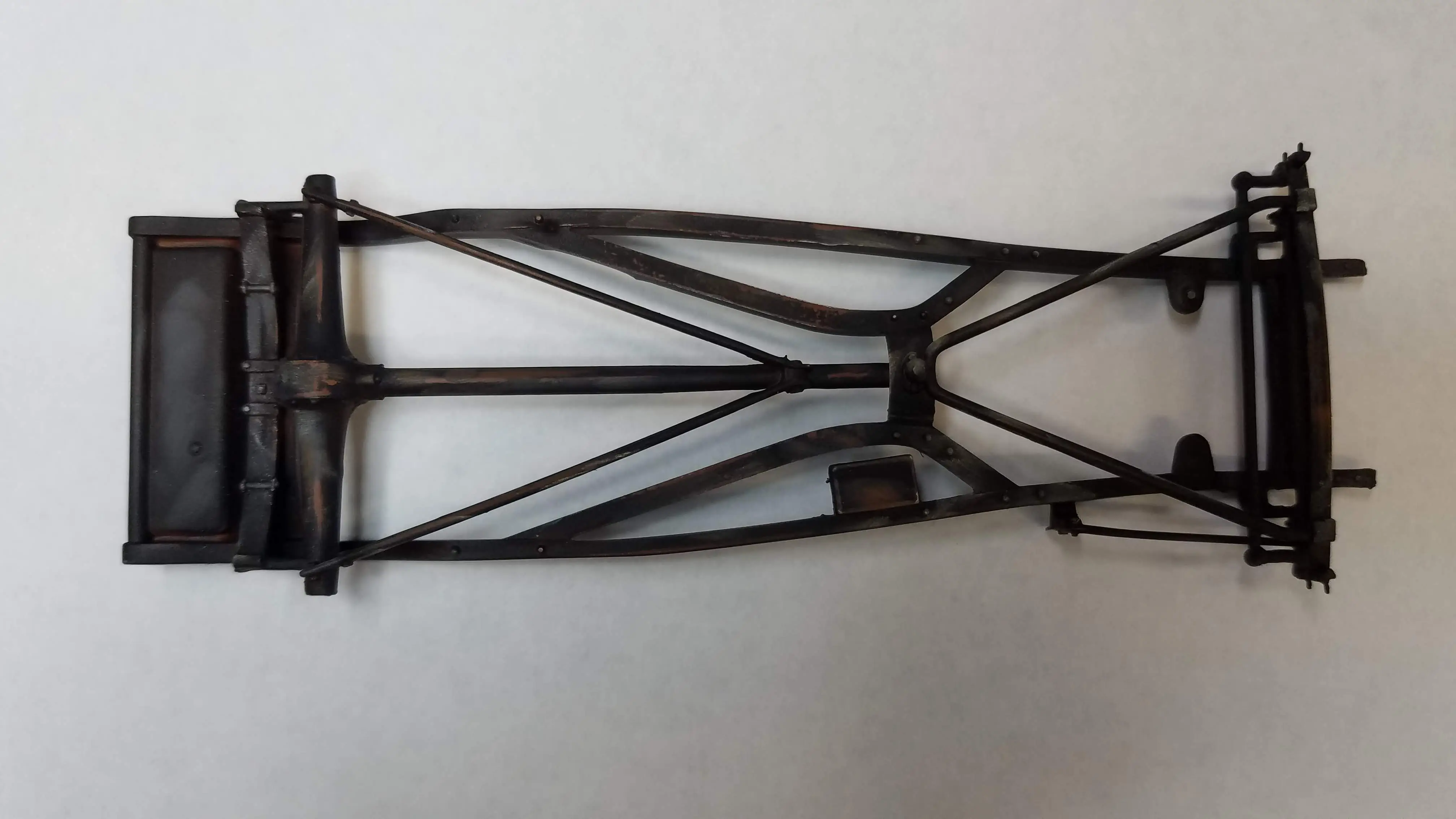
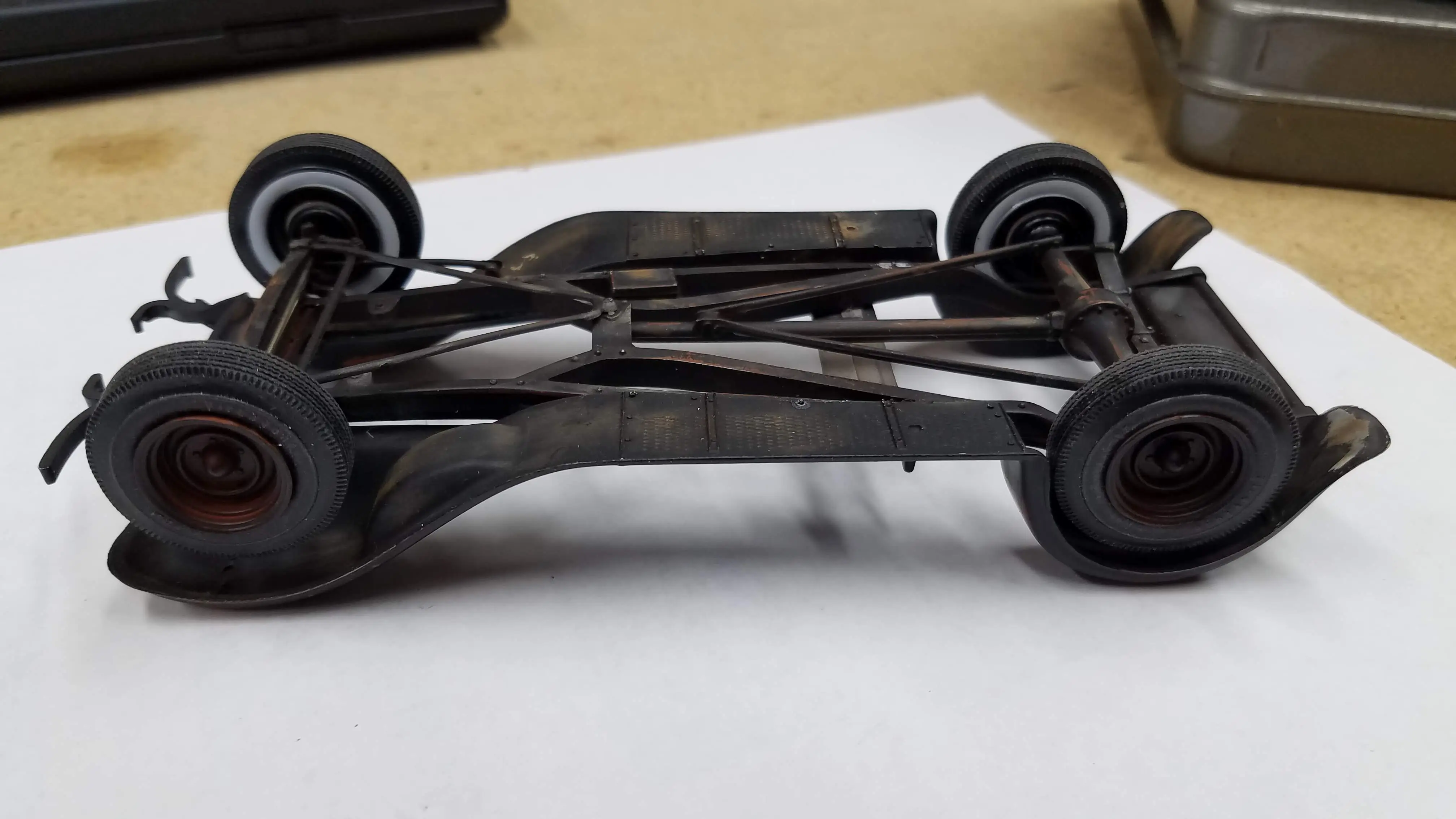
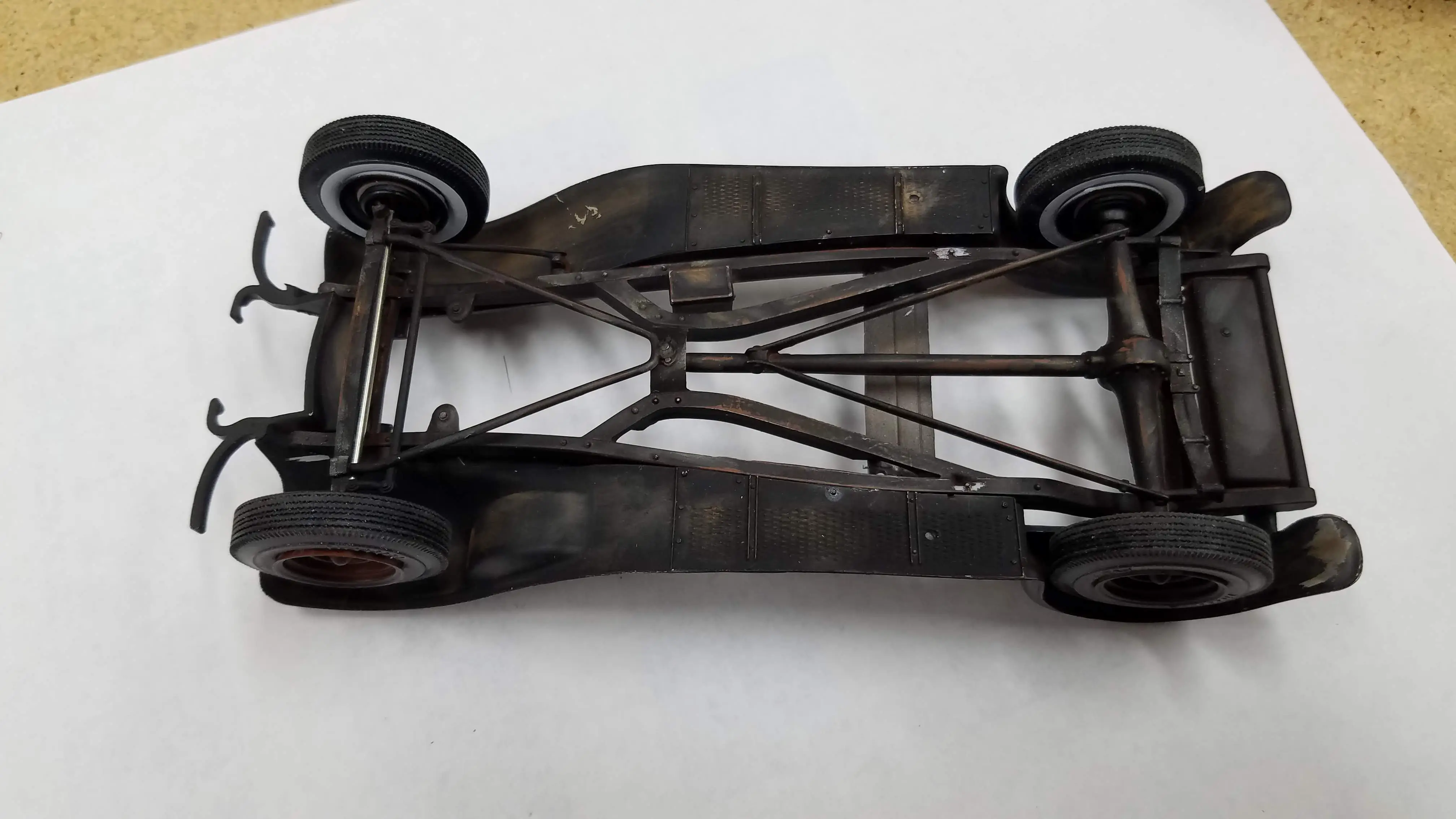
 Preparing the frame for first coat of rust
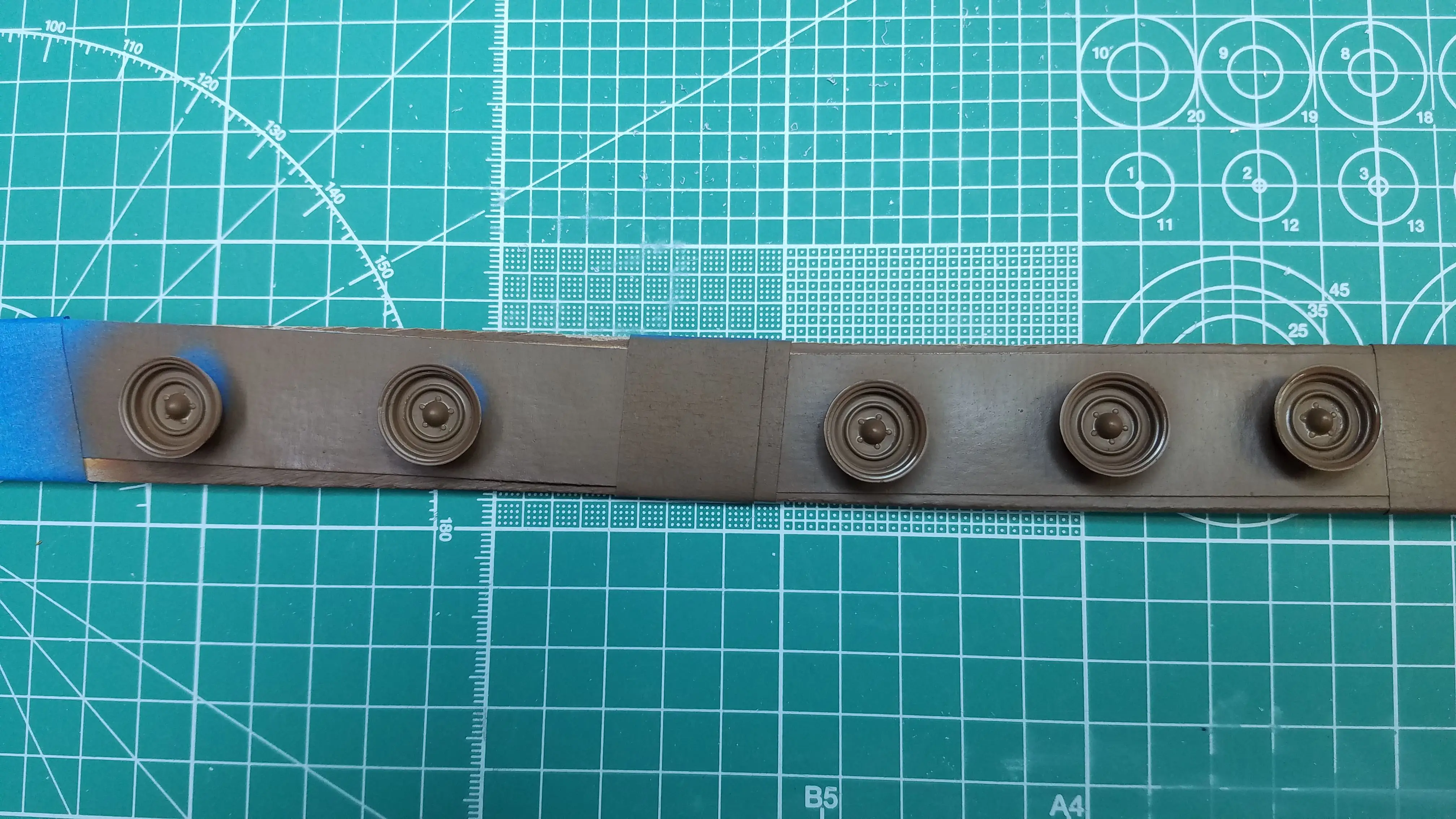
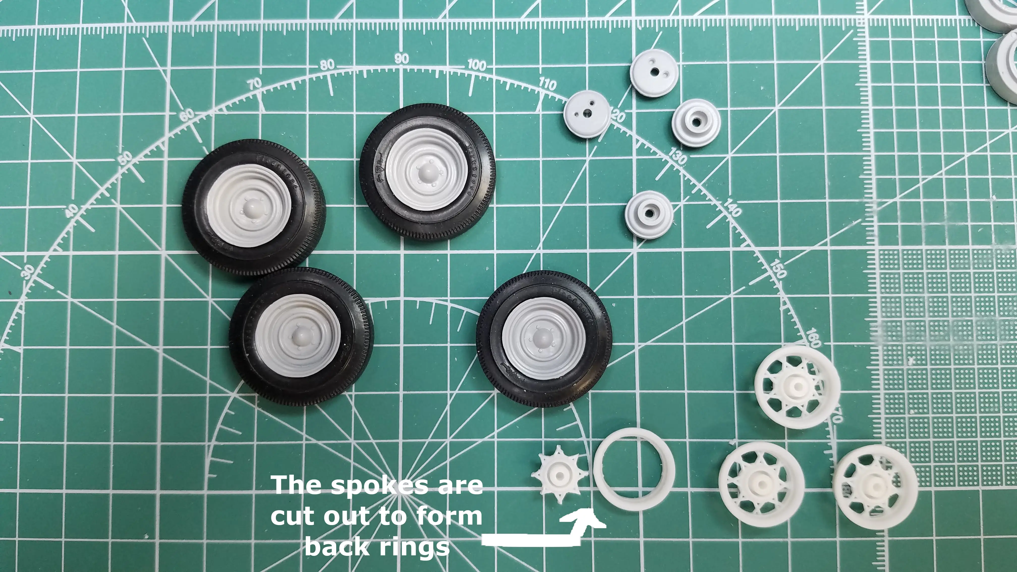 Using the solid steel wheels
 Test fitting interior floor and seat
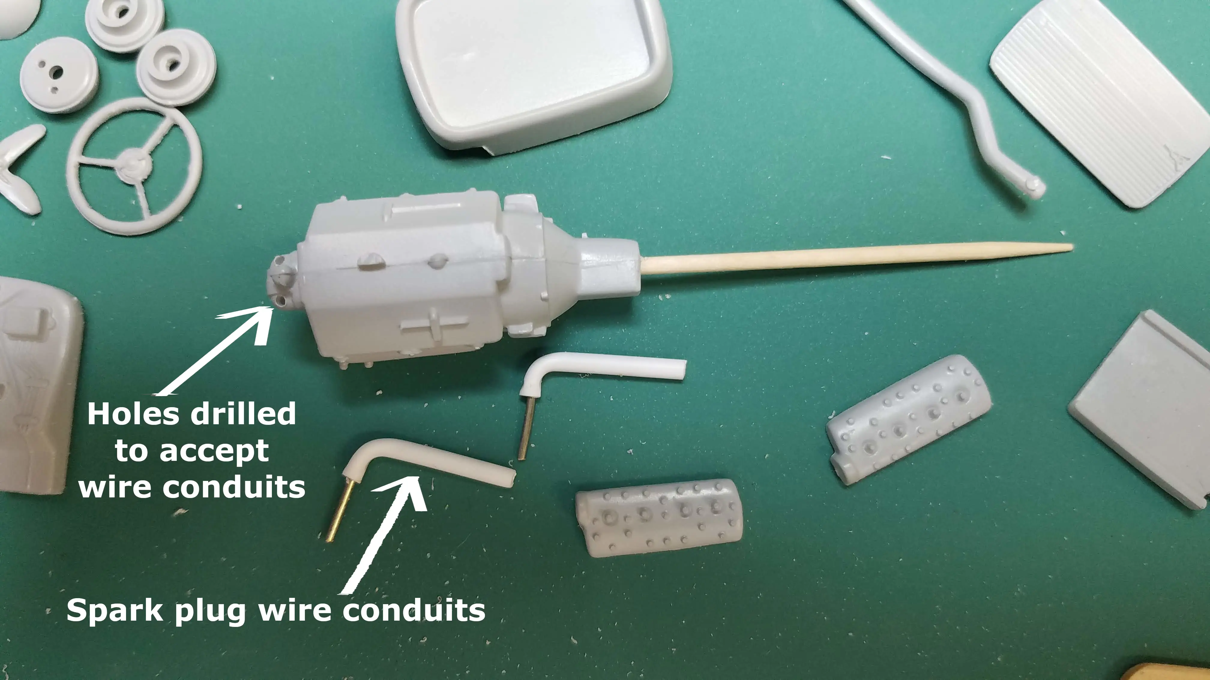
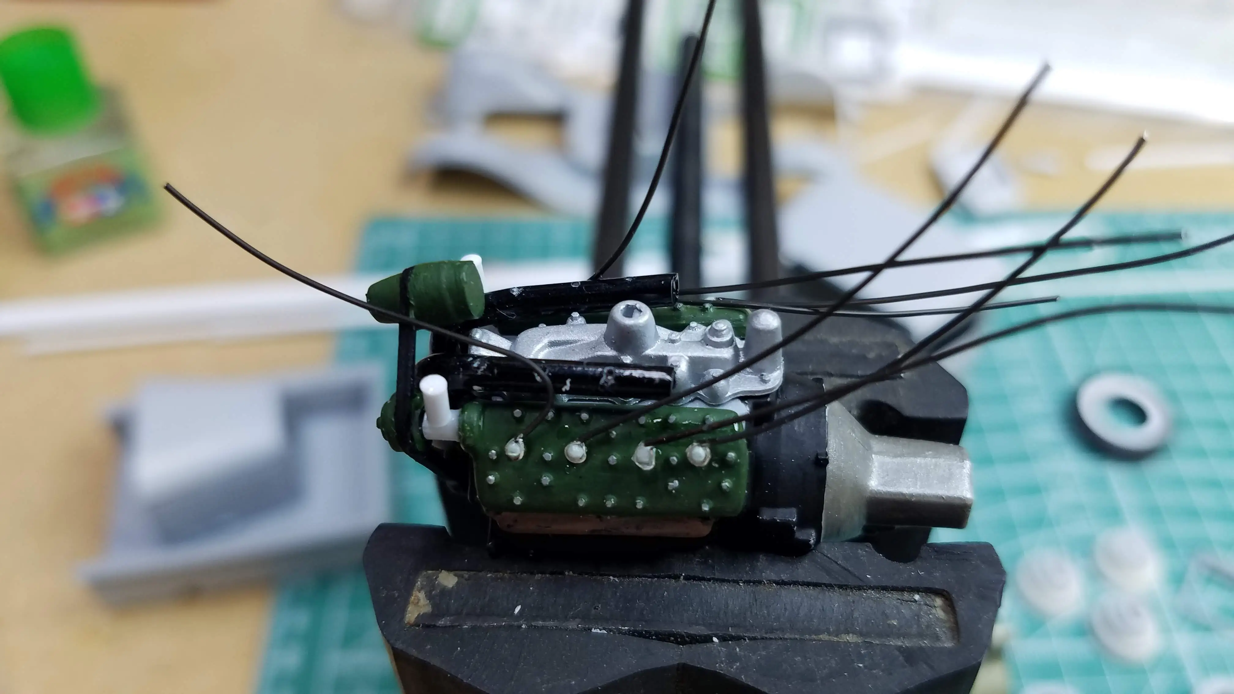 Wiring the spark plug
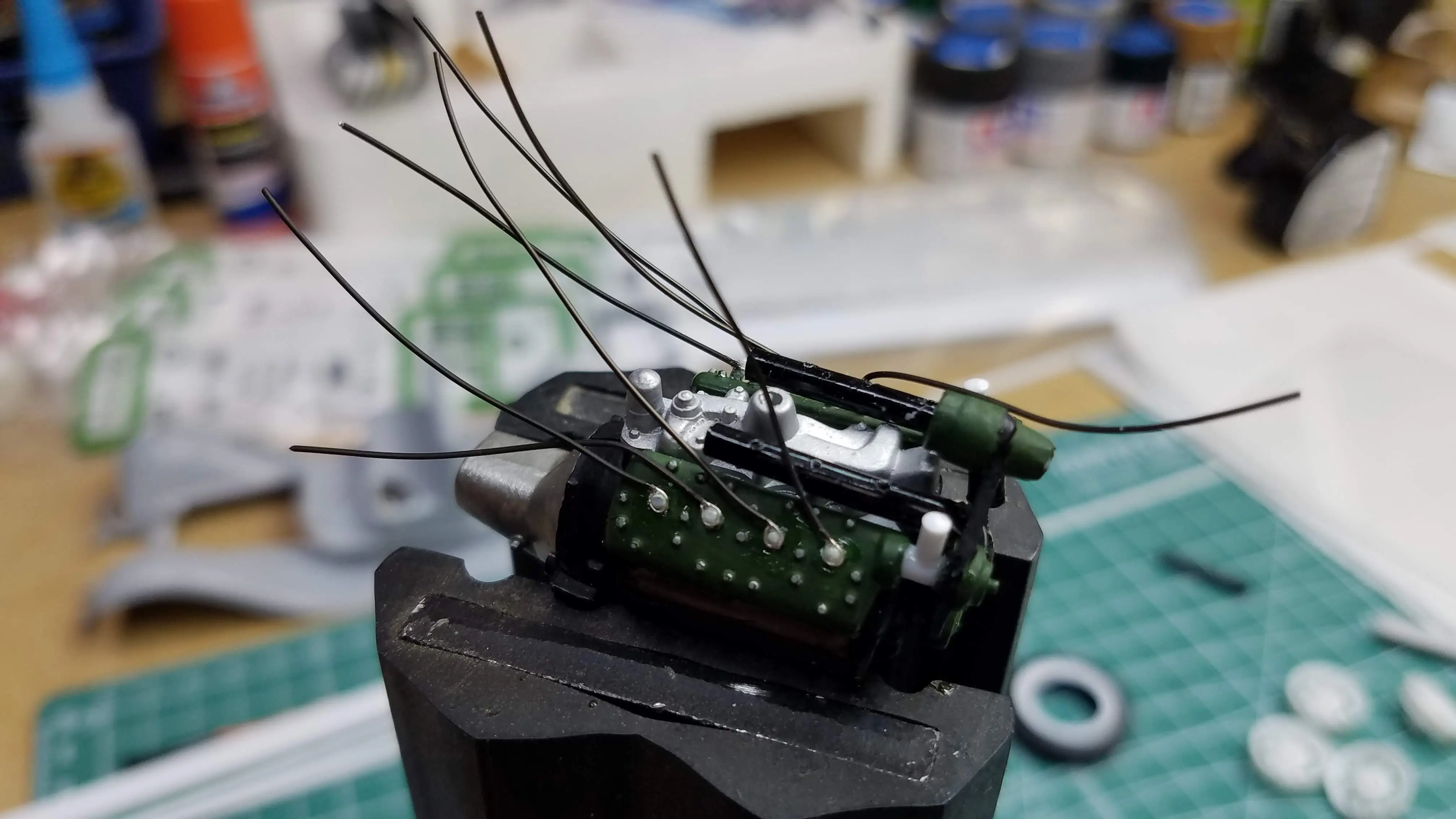 Wiring the spark plug
 First coat of rust applied
 First coat of rust applied
 First coat of rust applied
 First coat of rust applied
 Spark plug wires placed in wiring conduits
 Spark plug wires placed in wiring conduits
 Spark plug wires placed in wiring conduits
 Spark plug wires placed in wiring conduits
 Another layer of rust on frame and fenders
 Another layer of rust is added
 Another layer of rust is added
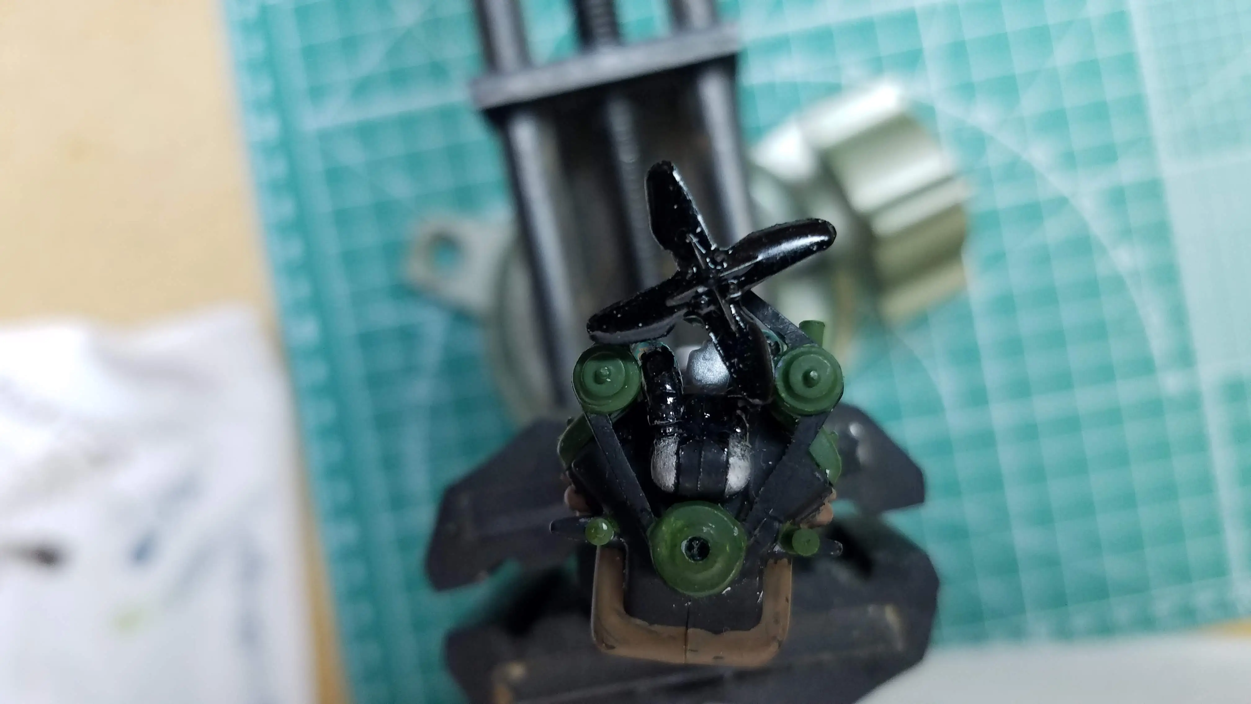 Engine cooling fan installed
 Engine cooling fan installed
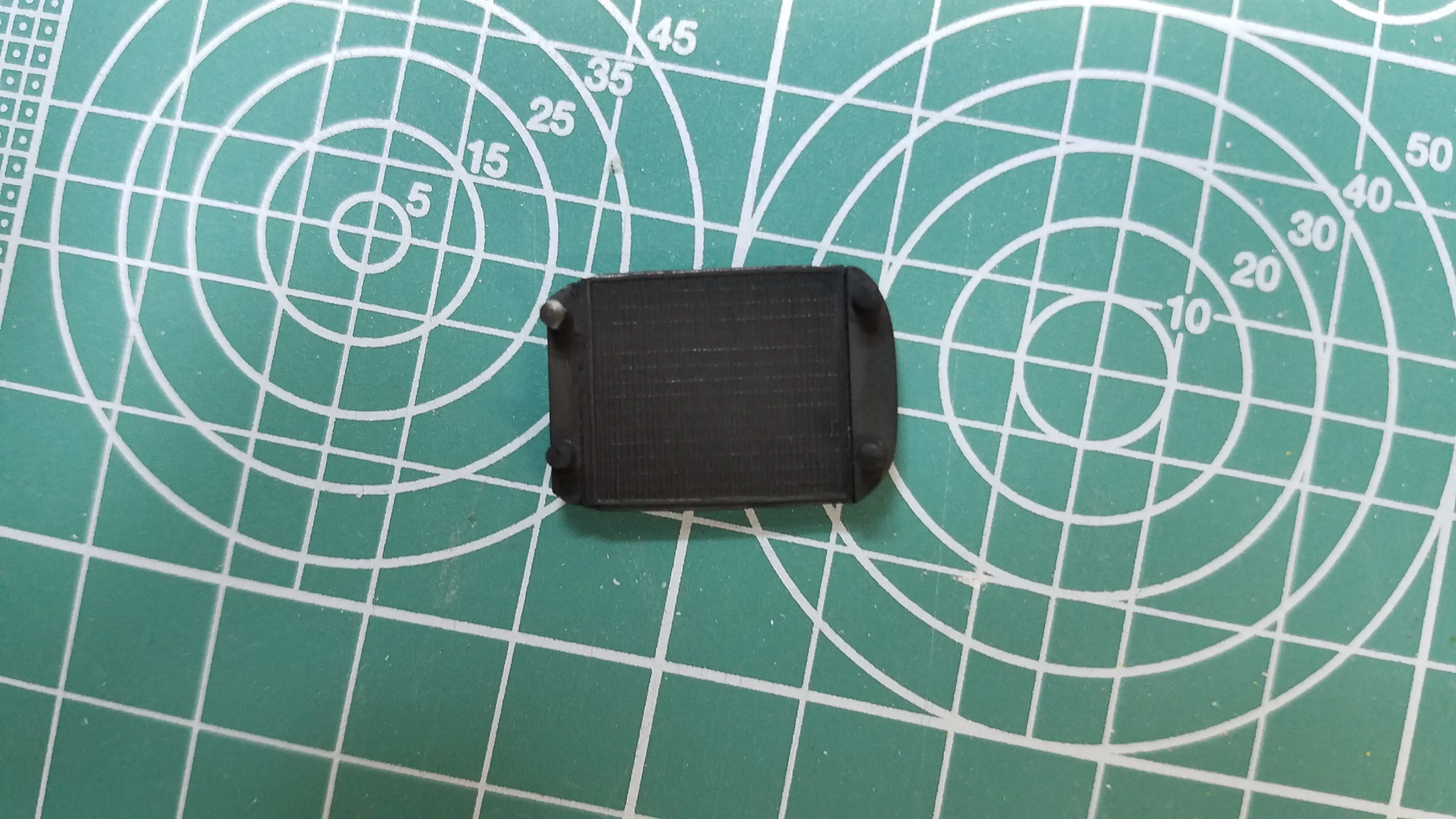 Scratch build radiator painted
 Scratch built radiator dirtied and aged
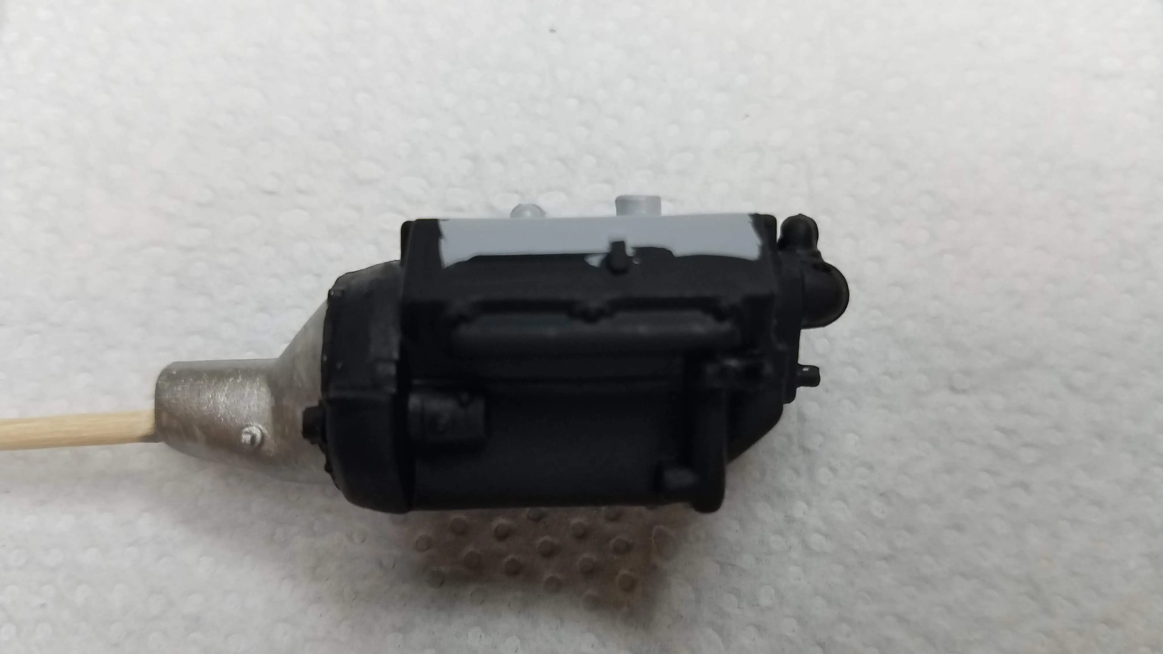
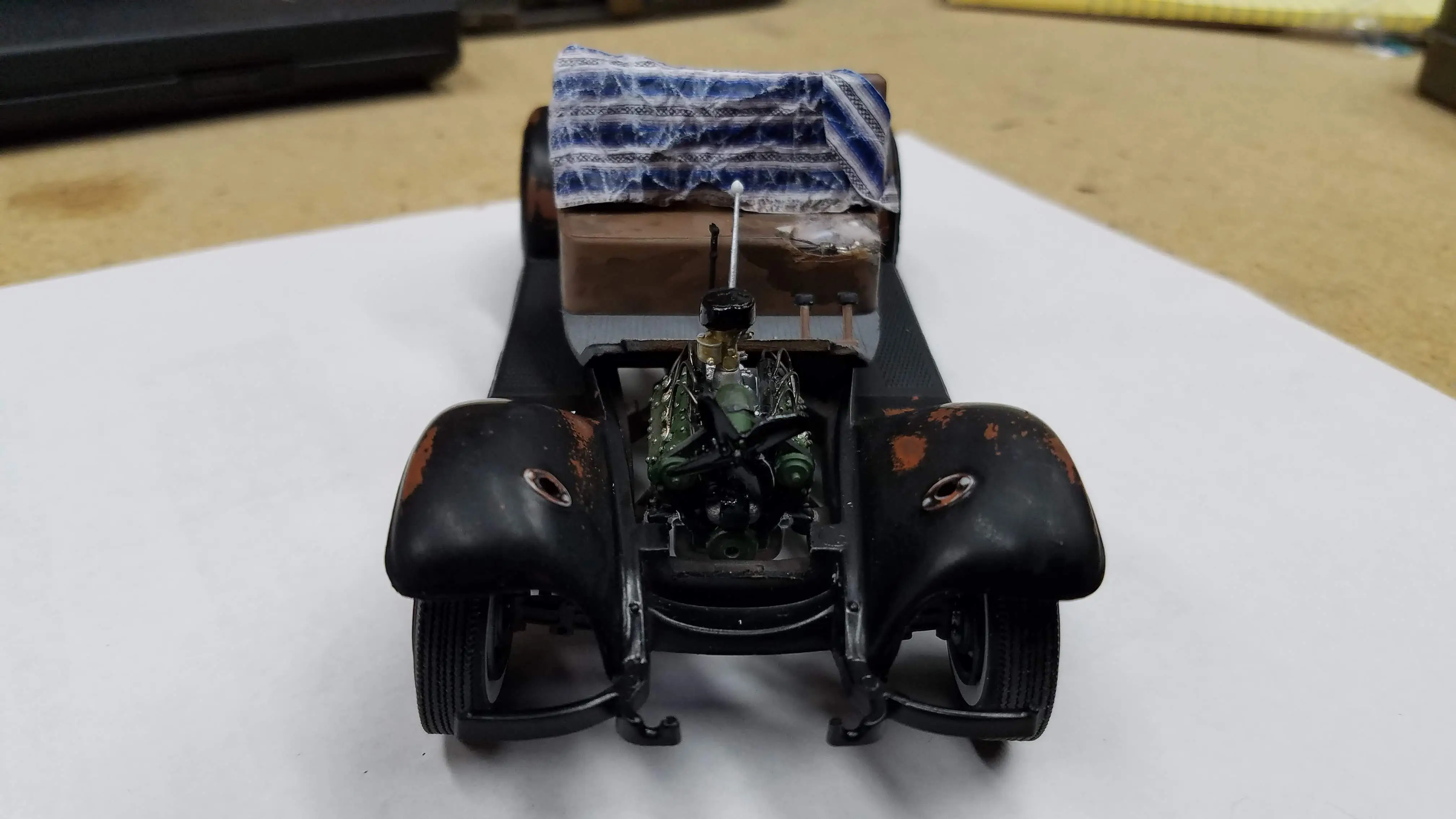
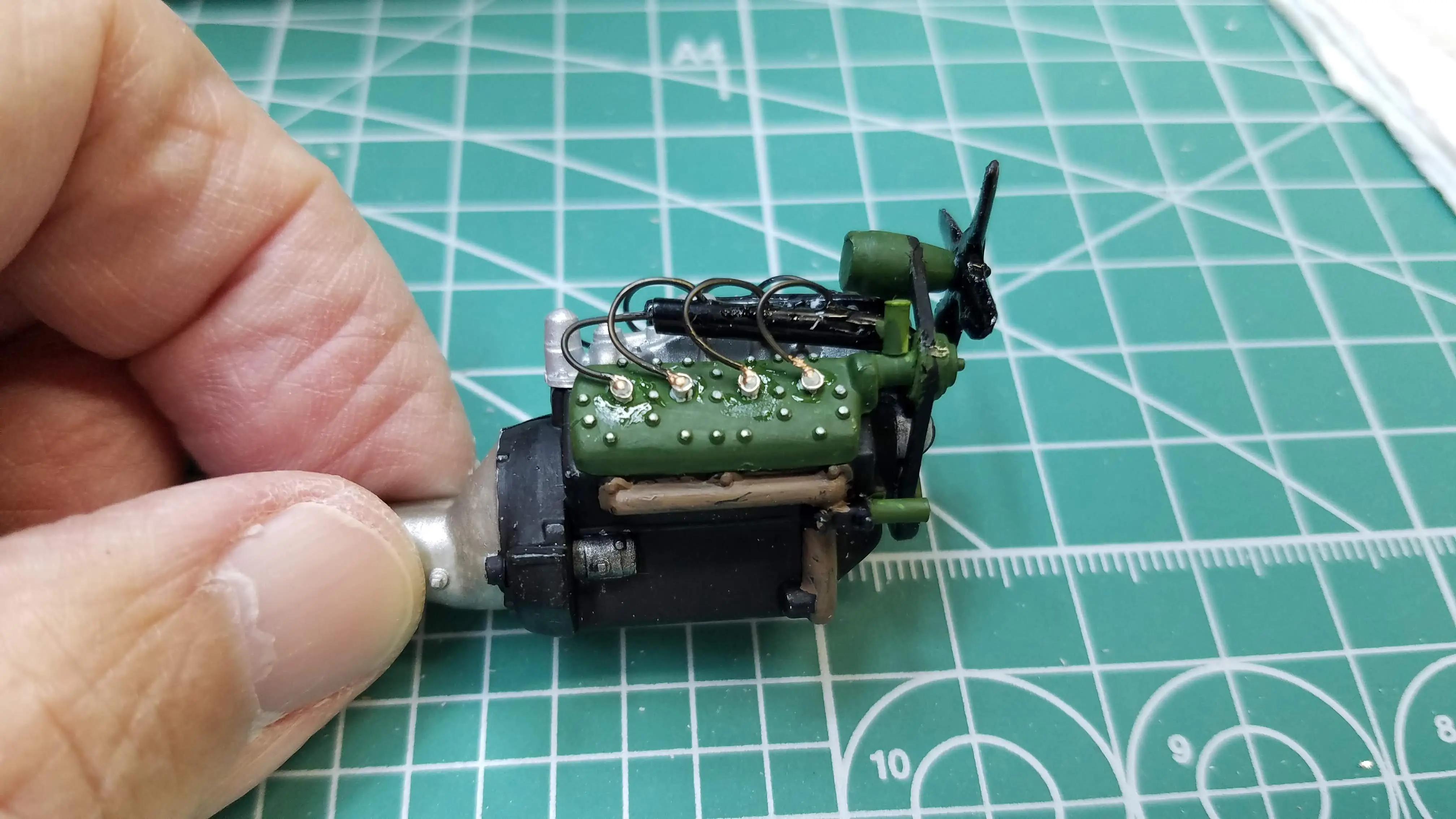 Completed engine before I dirty it
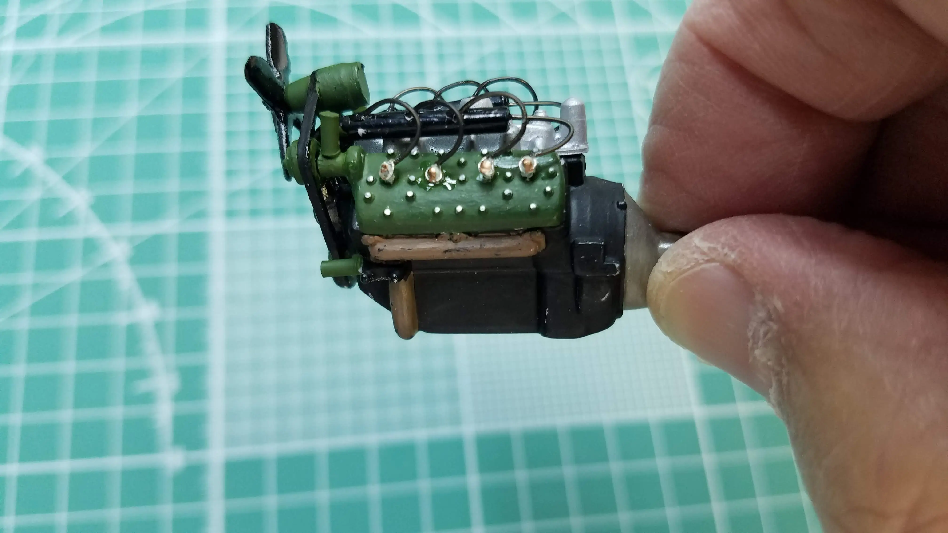 Completed engine before I dirty it
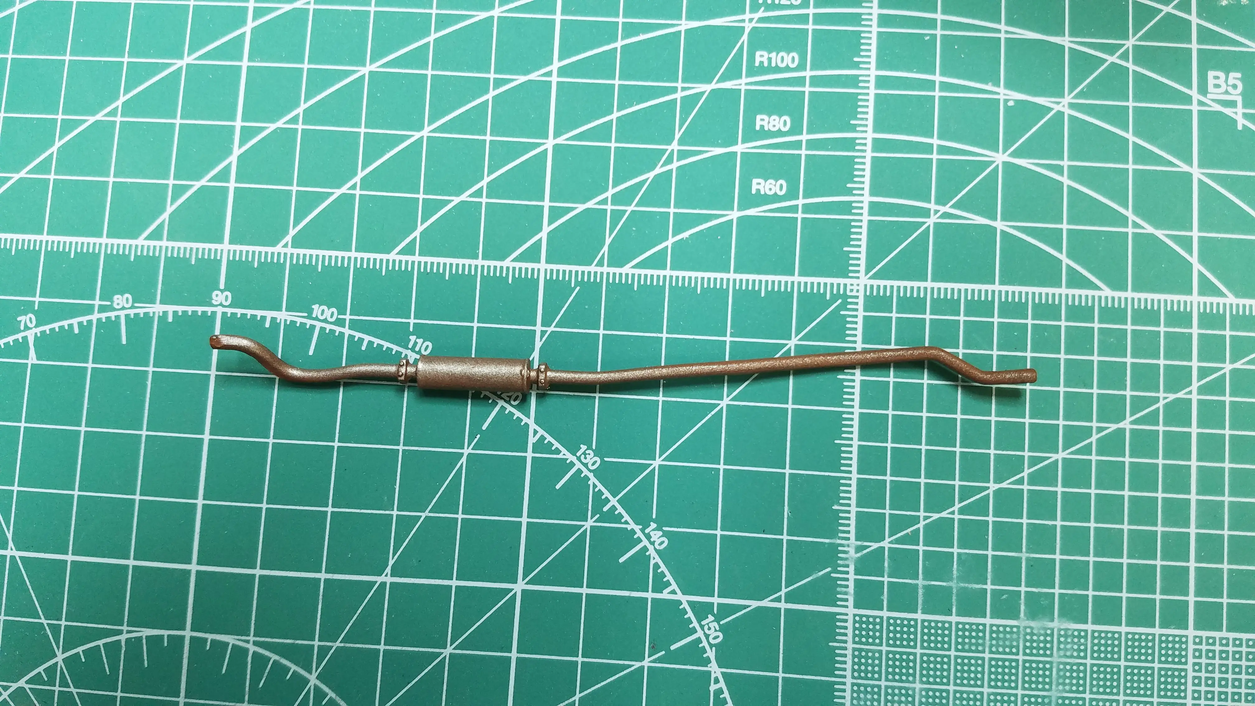 Exhaust pipe and muffler painted
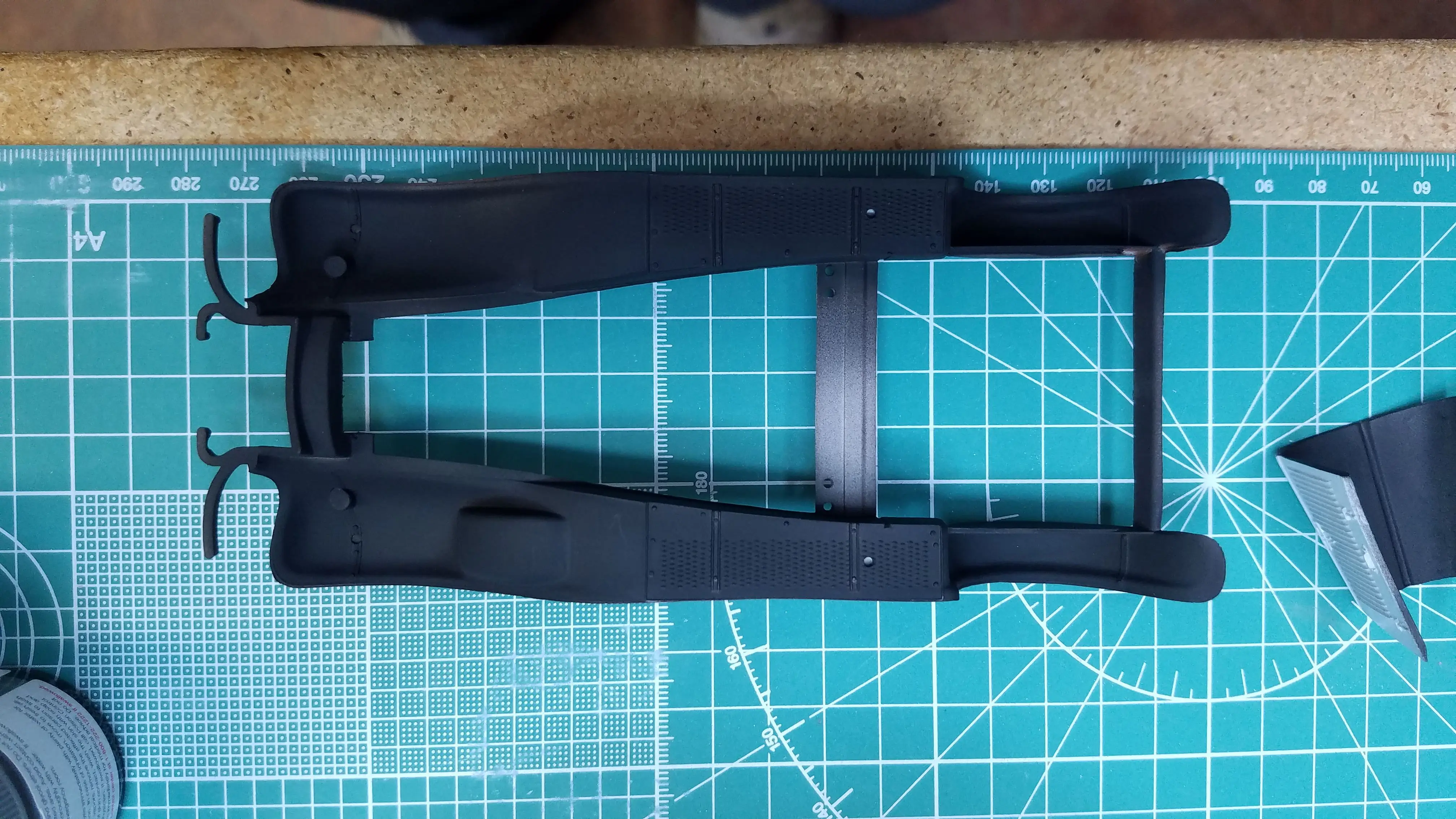
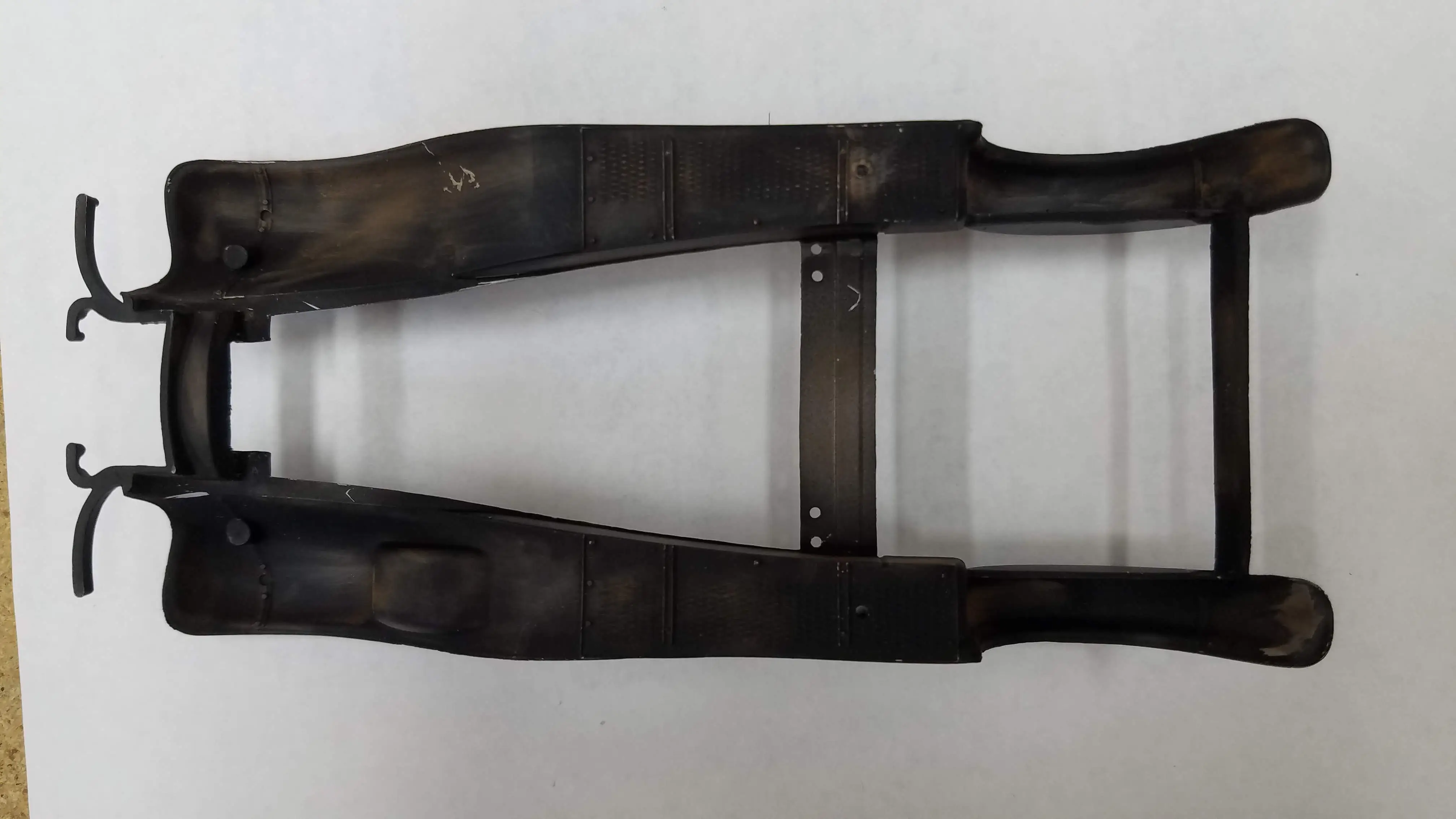
 Frame lightly airbrushed
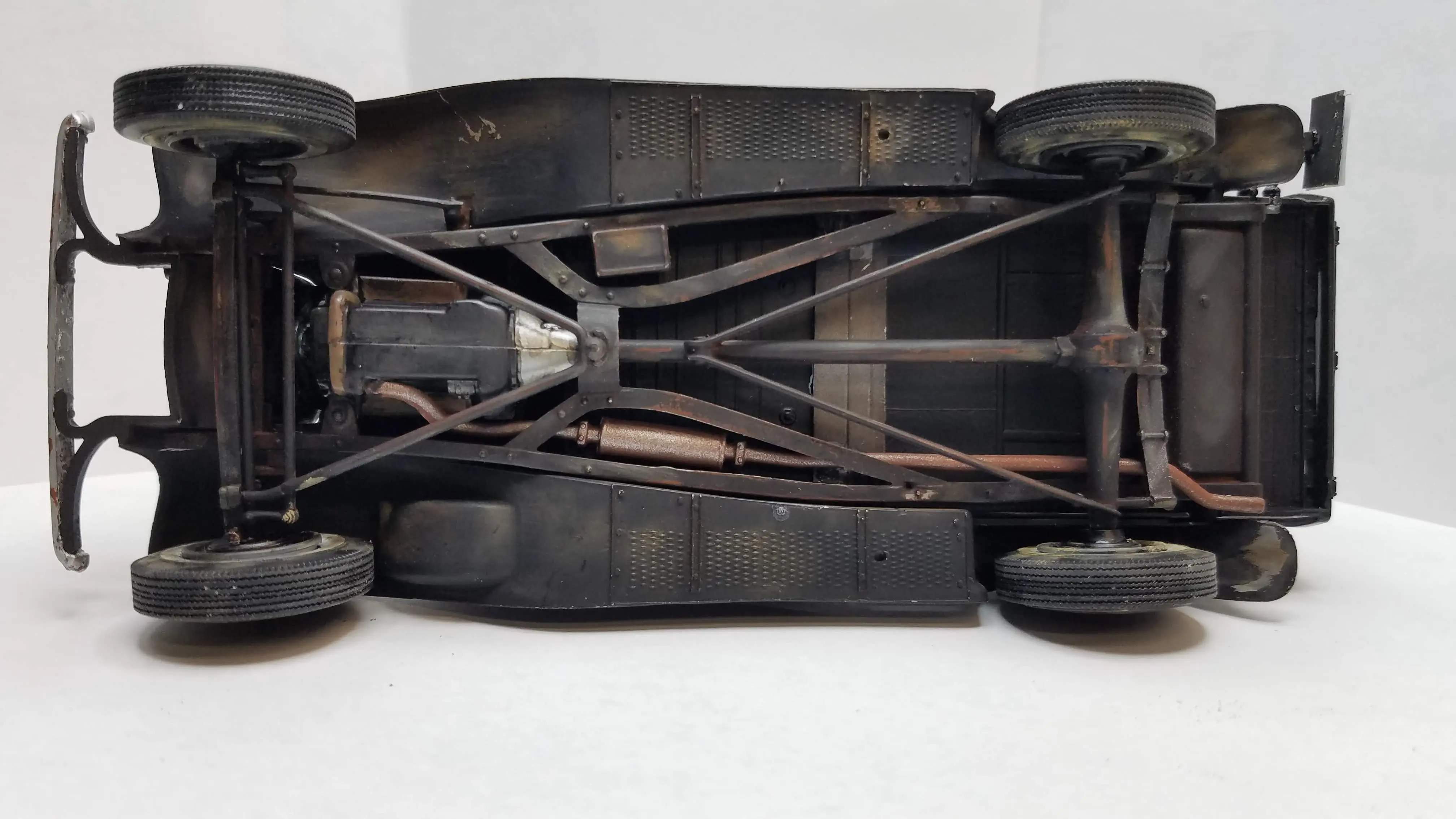
 Underside of frame, fenders and engine shroud painted
 Cab floor painted
 Bottom of floor pan painted
 Underside of the hood shroud is painted
 Inside of the radiator housing painted
 First layer of dirt applied to the truck bed
 The interior bench seat is painted
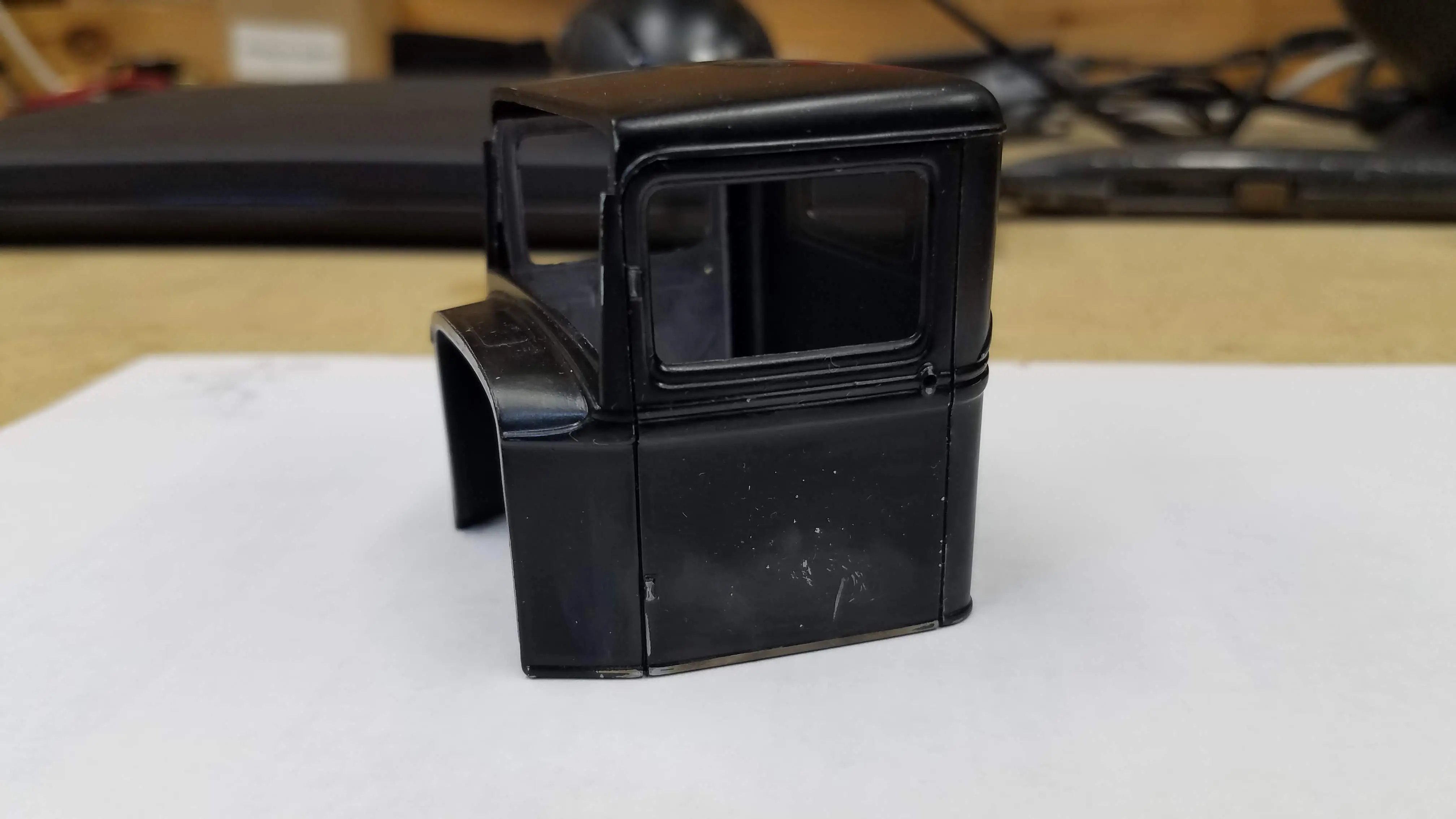
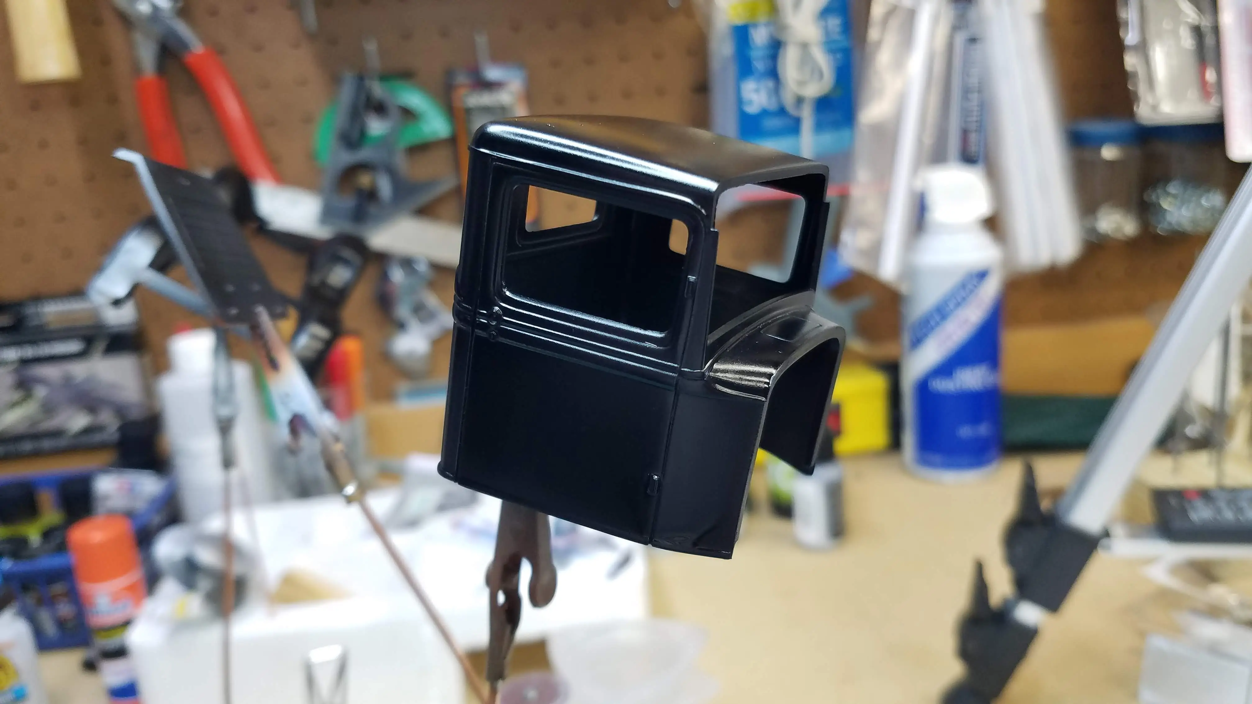 The truck cab is painted
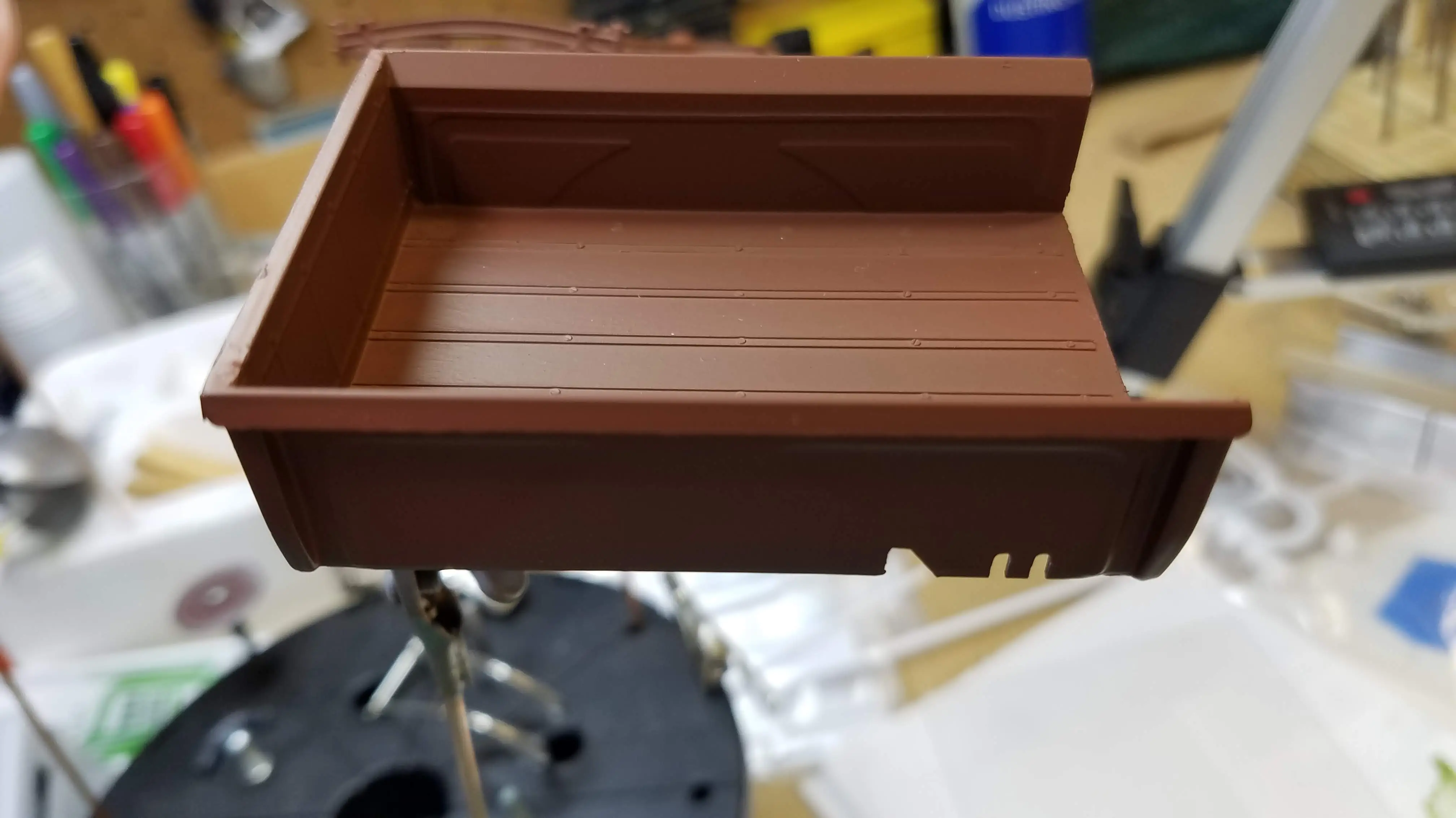
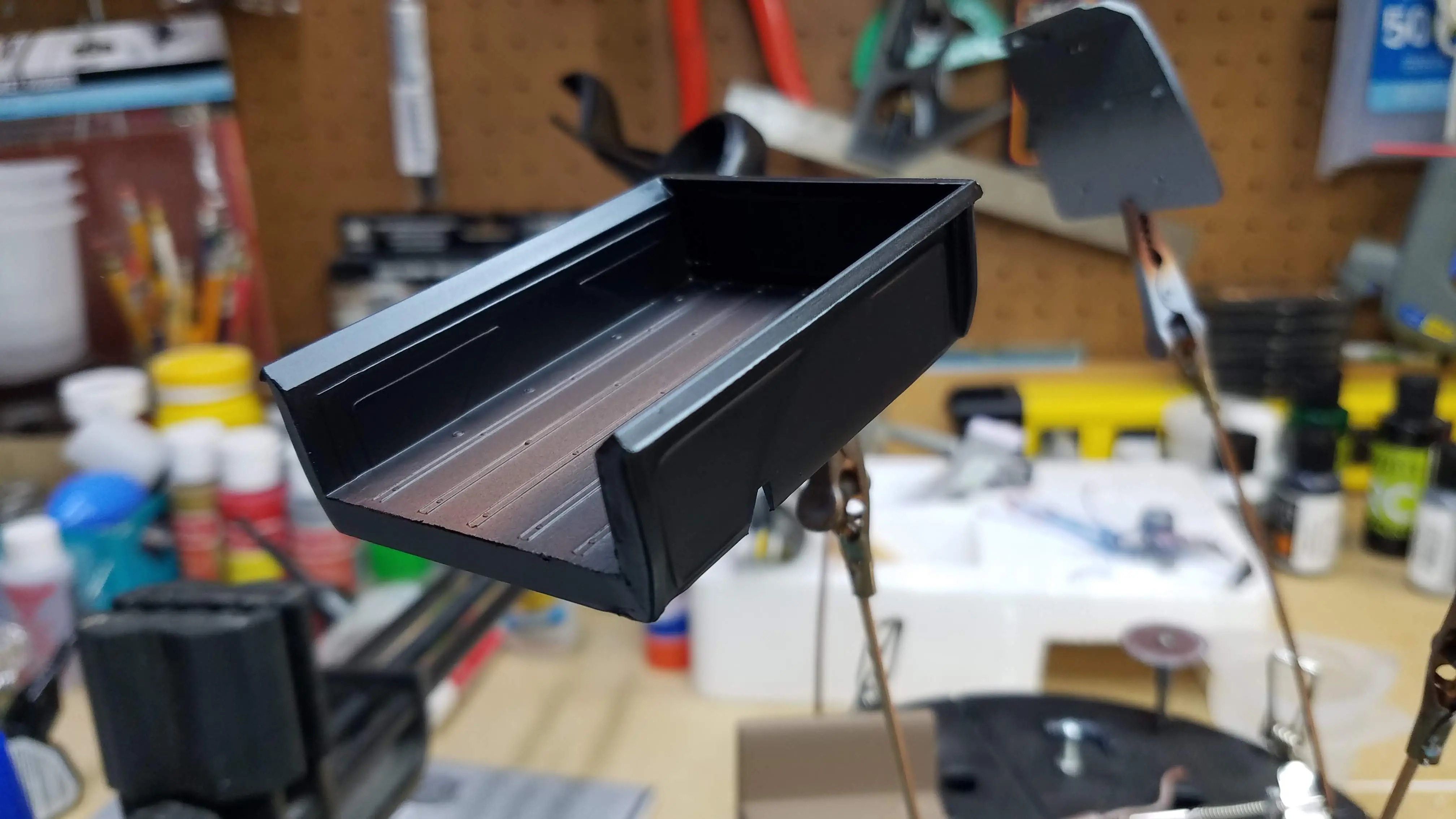 The truck bed gets painted
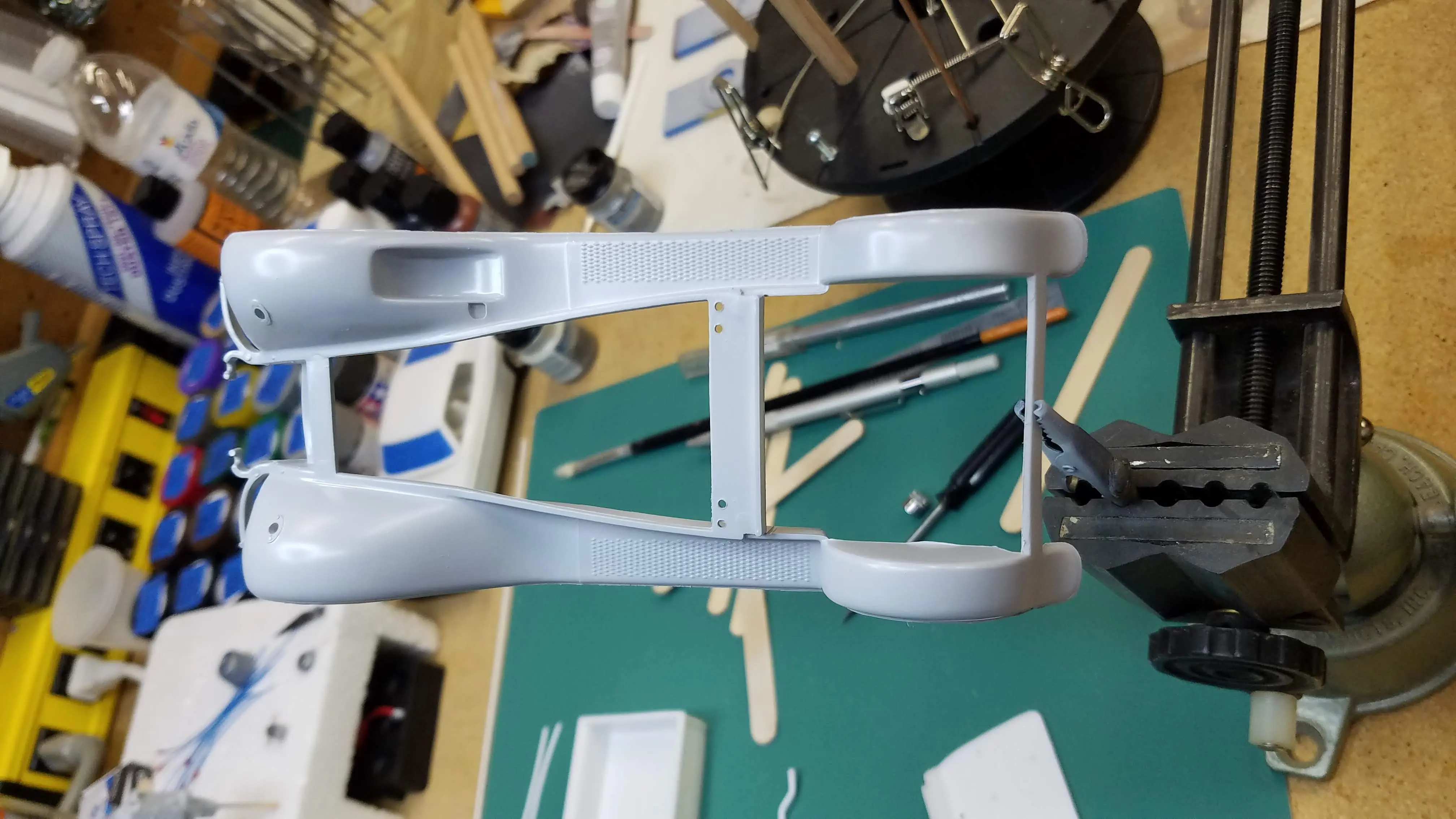
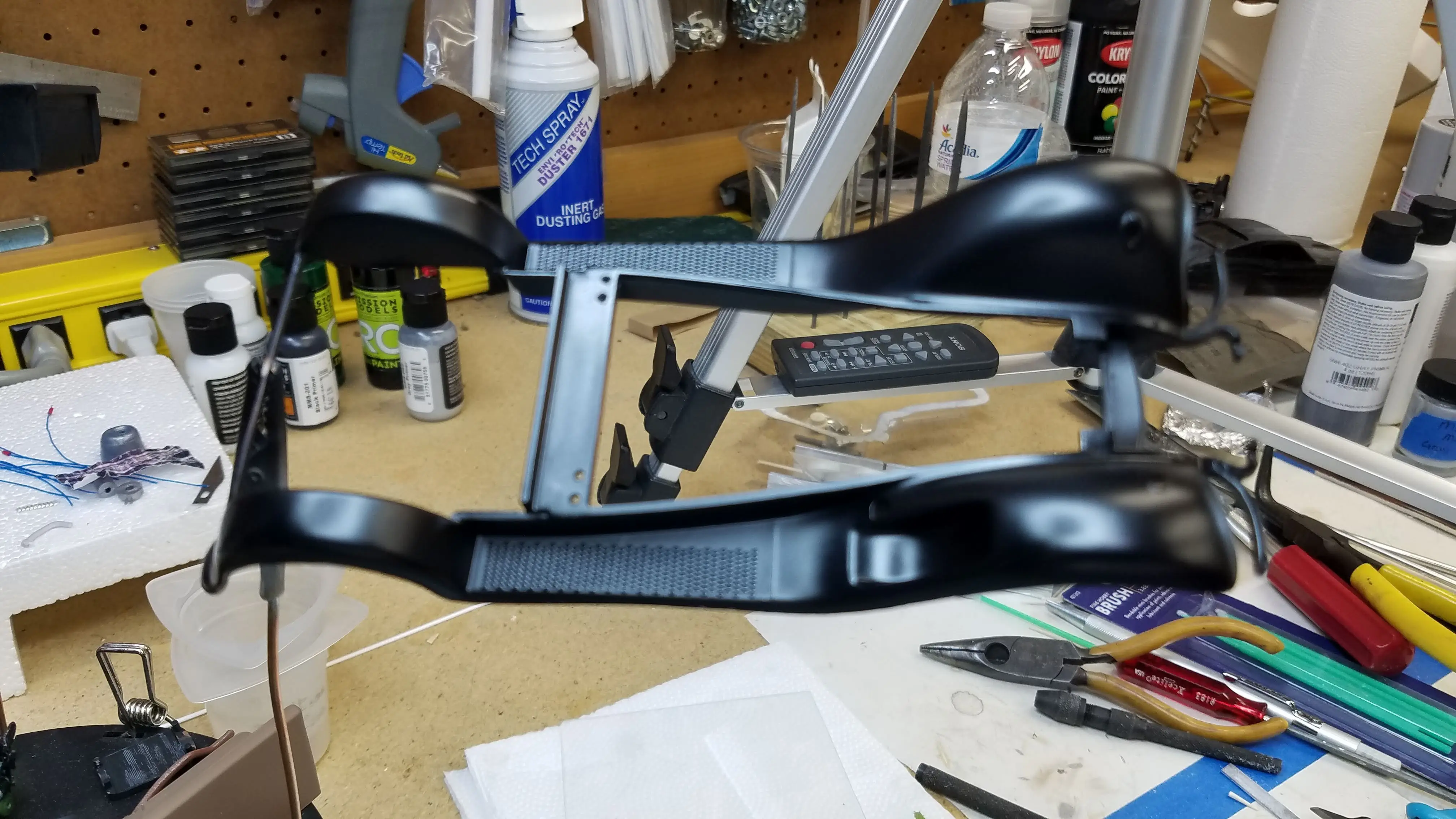 Chassis and fenders get painted
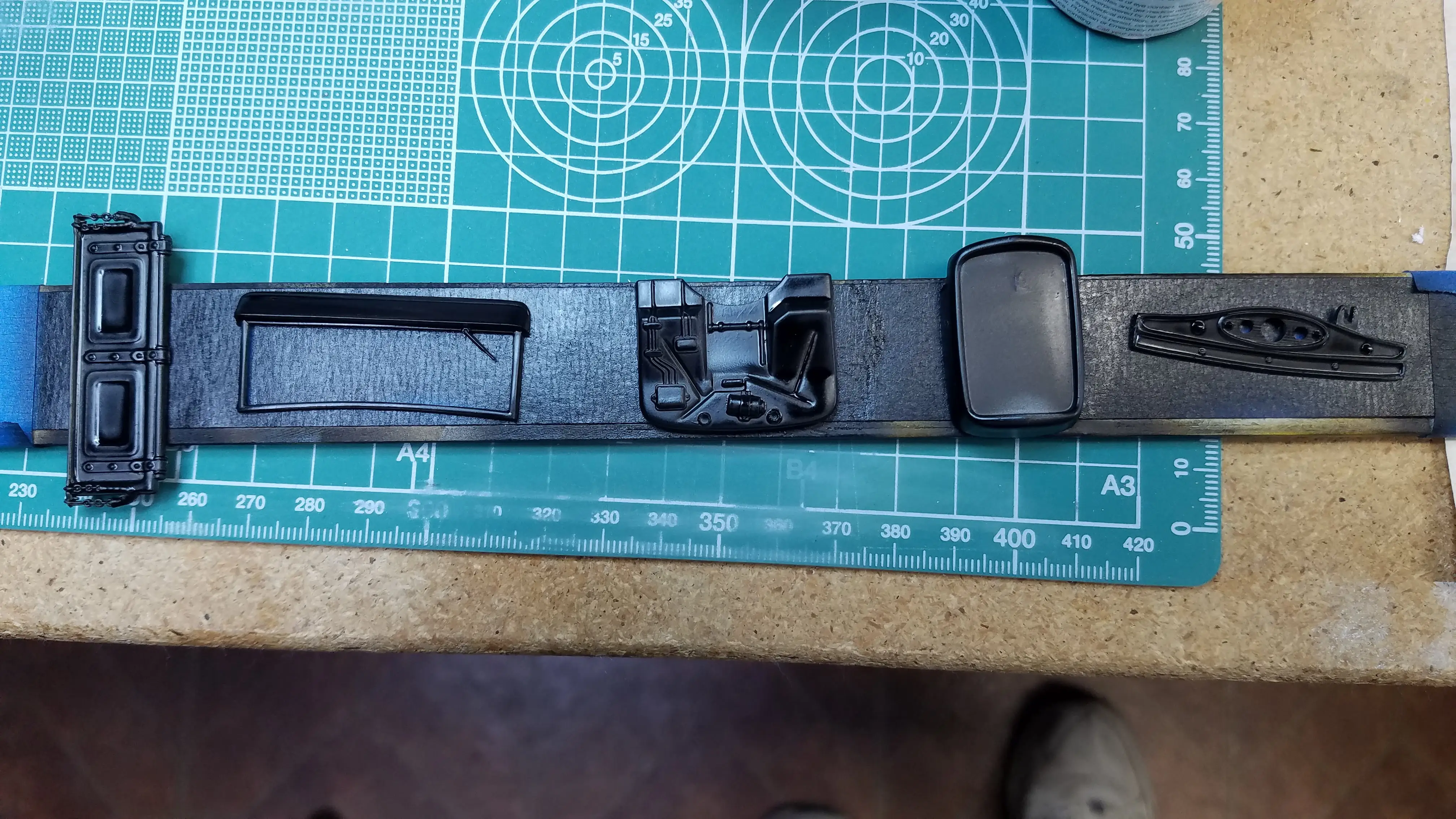 Other parts painted semi gloss black
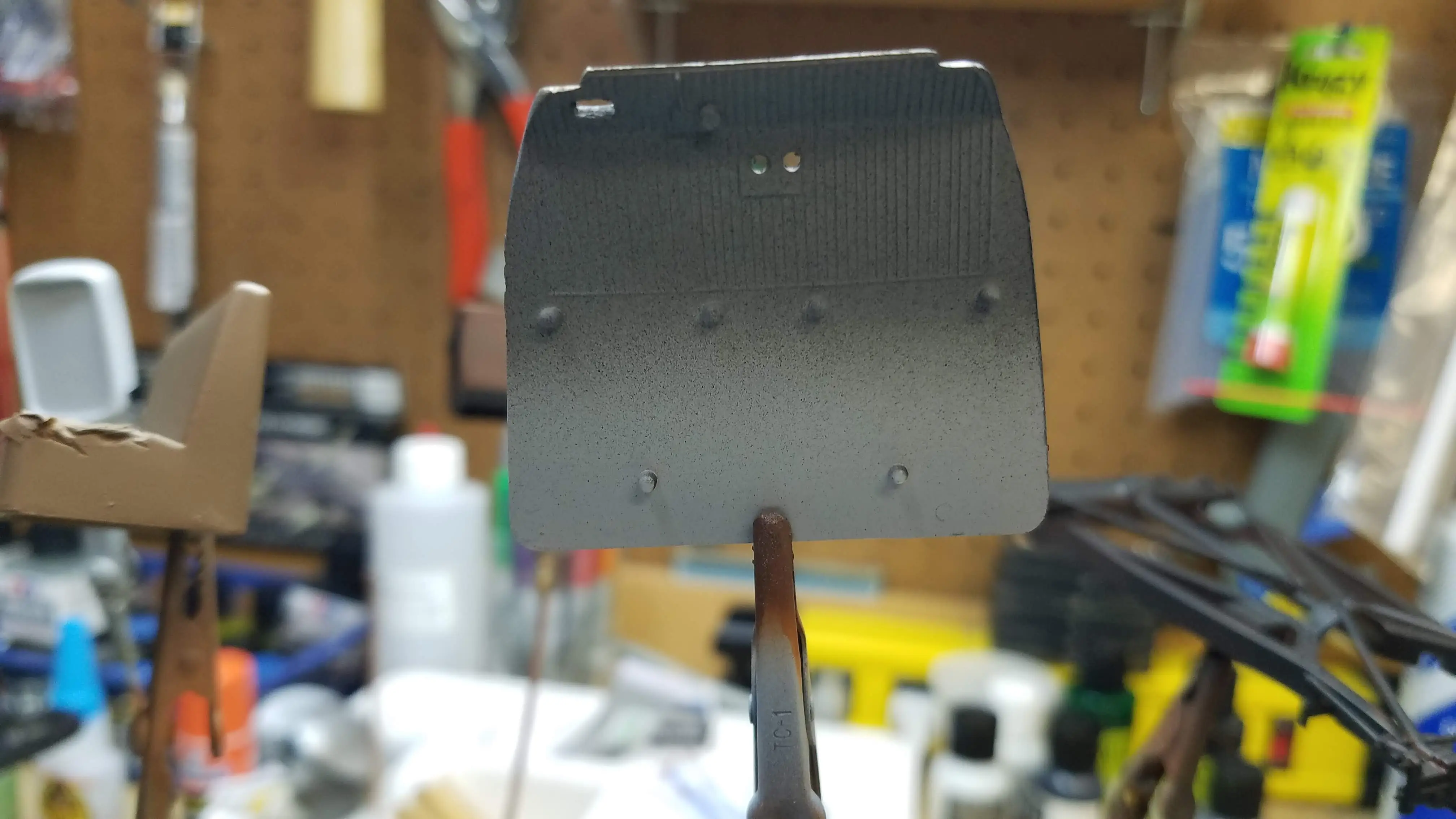
 Solid wheels lightly sprayed
 Frame is lightly sanded to show rust"
 Seat being dirtied
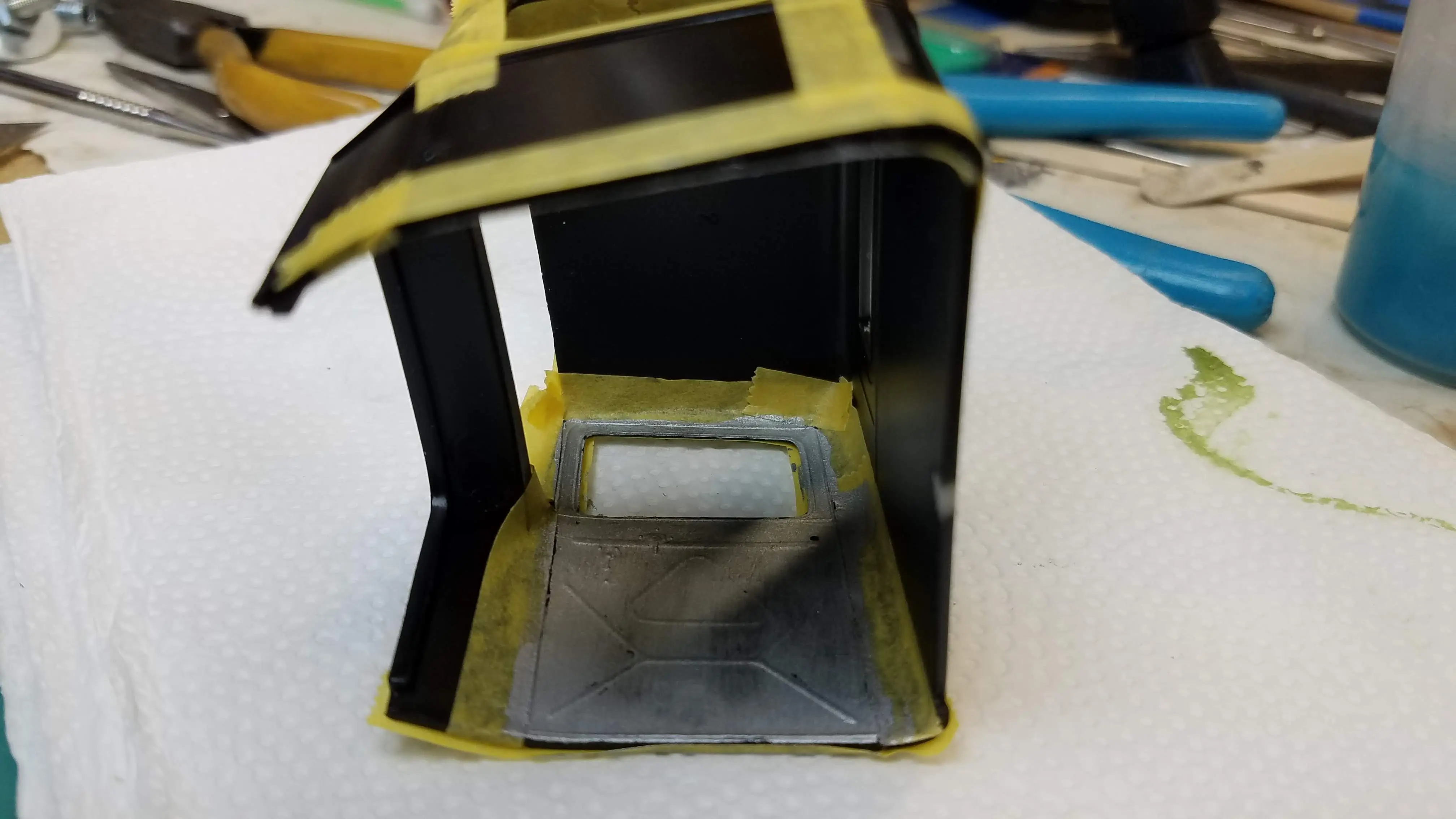
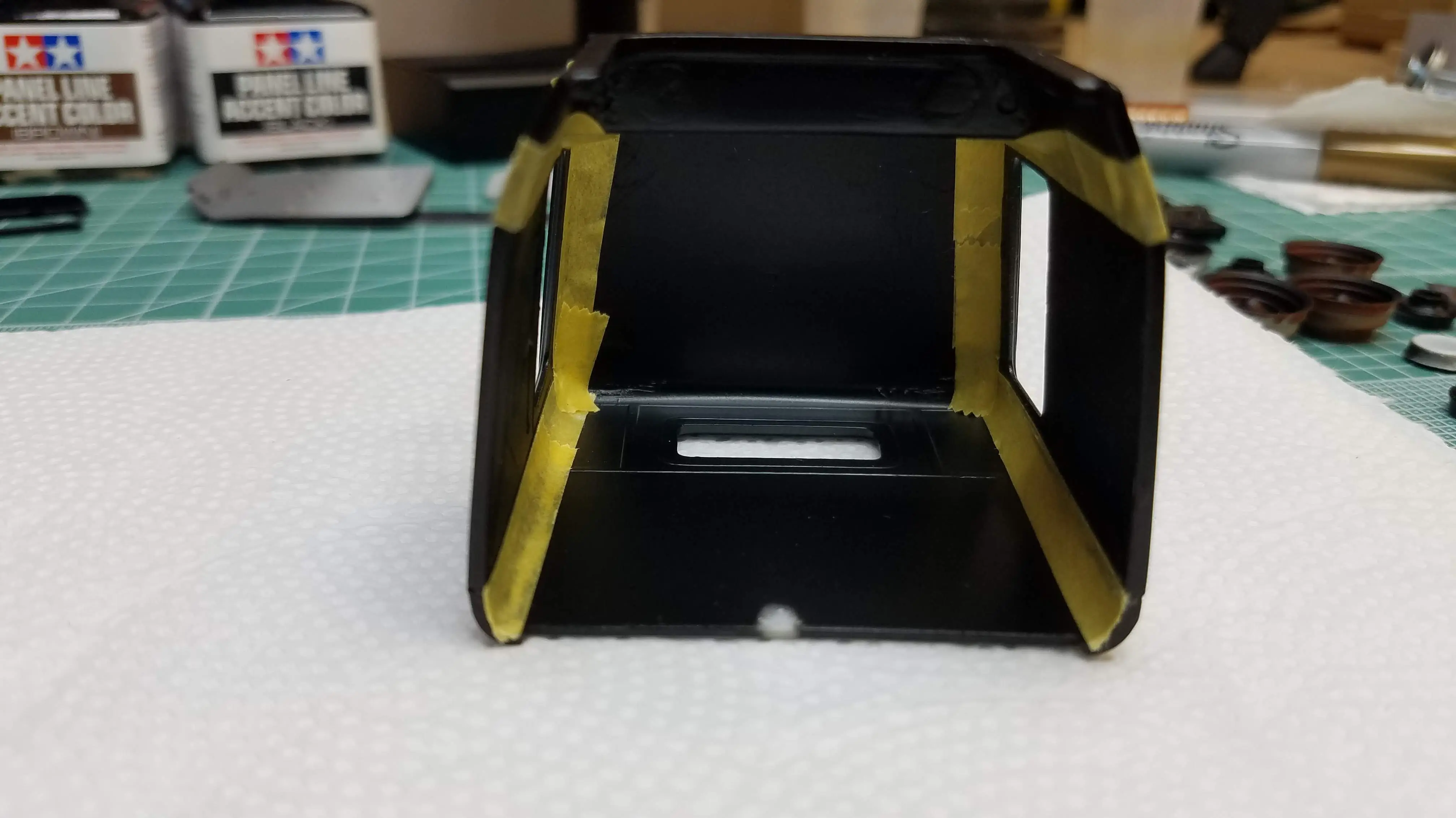 Masking the inside of the cab
 Gluing wheel fronts and back together
 Inside of cab door is painted
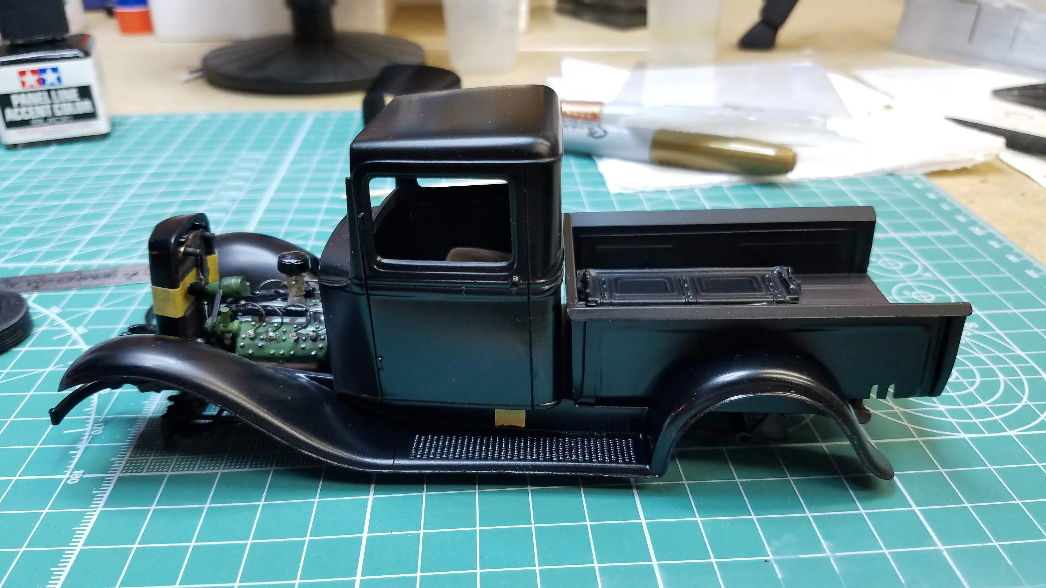
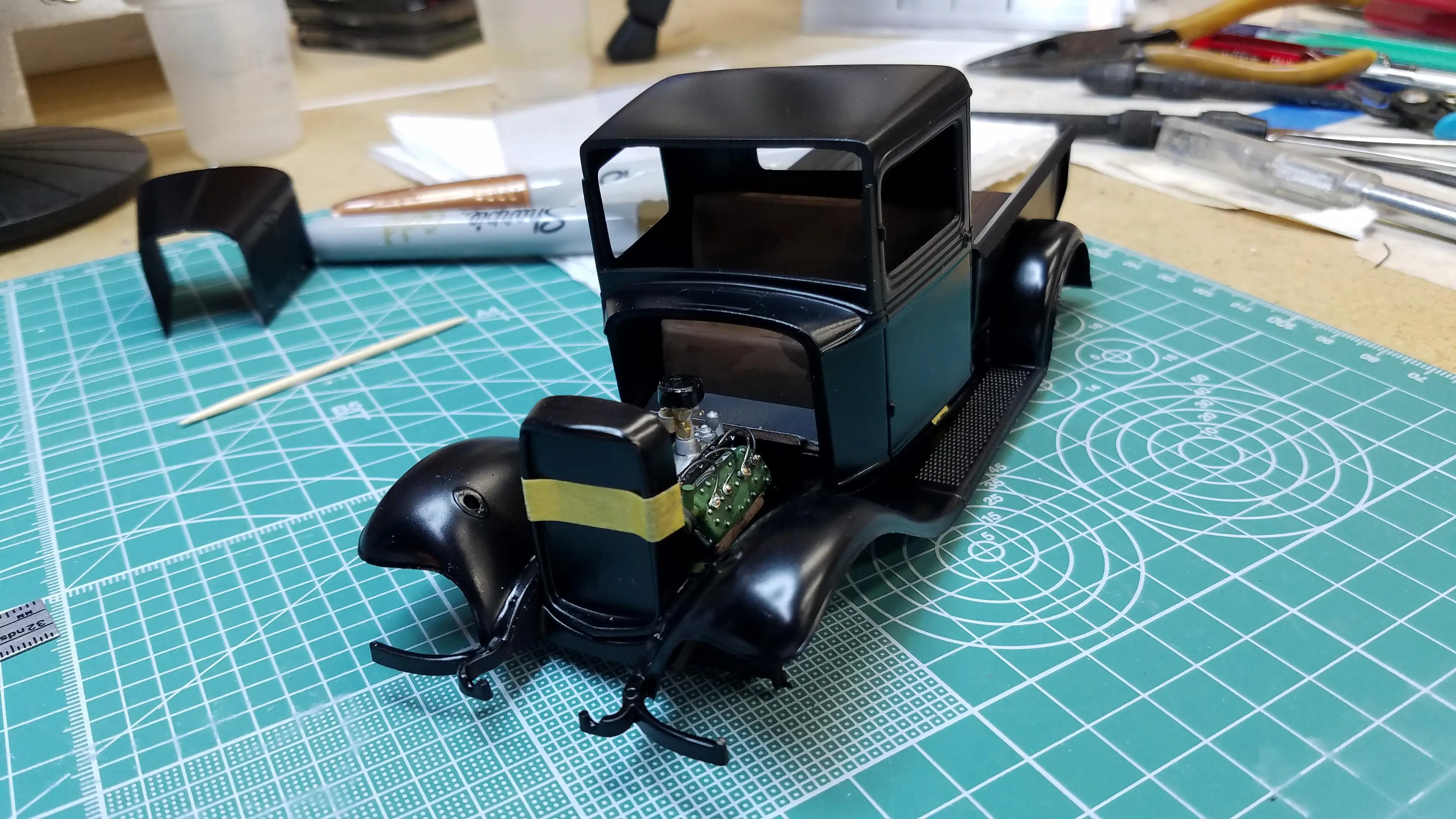
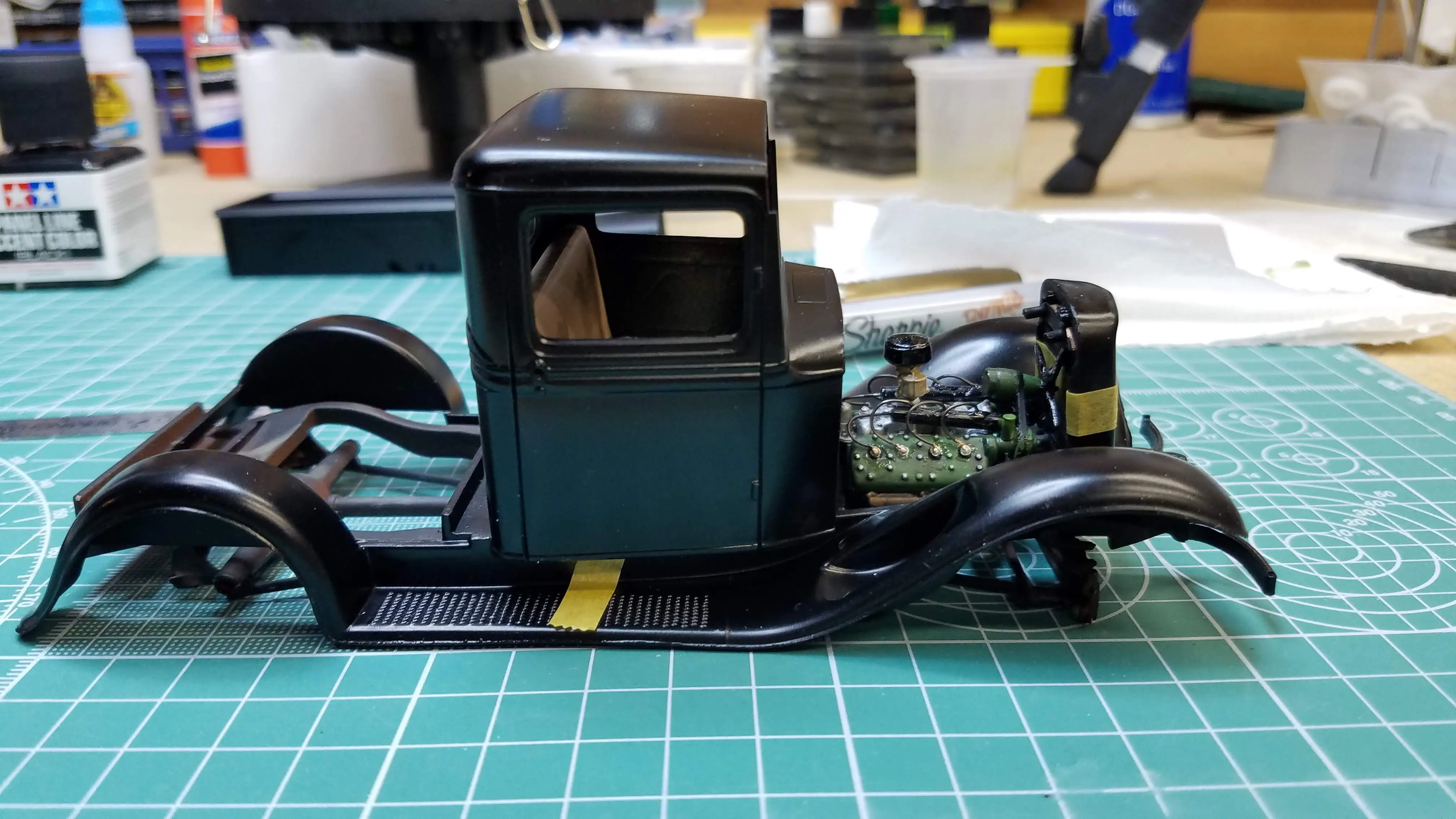 Dry fitting body and chassis
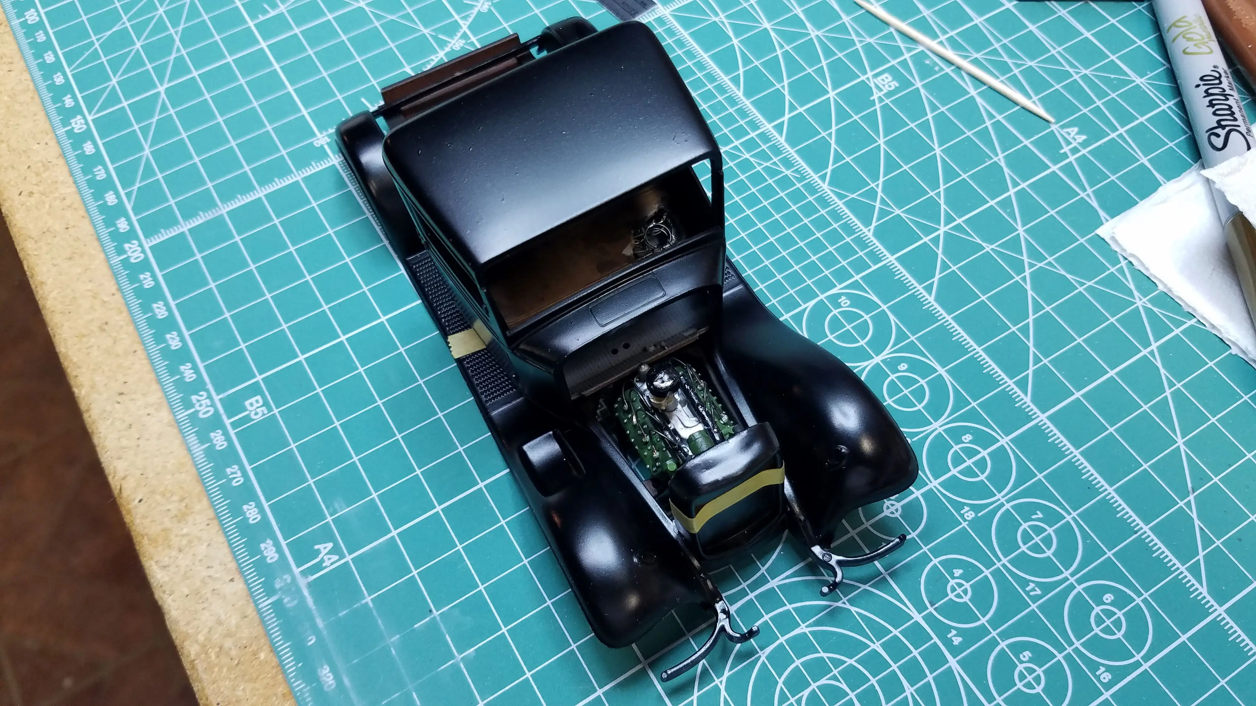 Dry fitting body and chassis
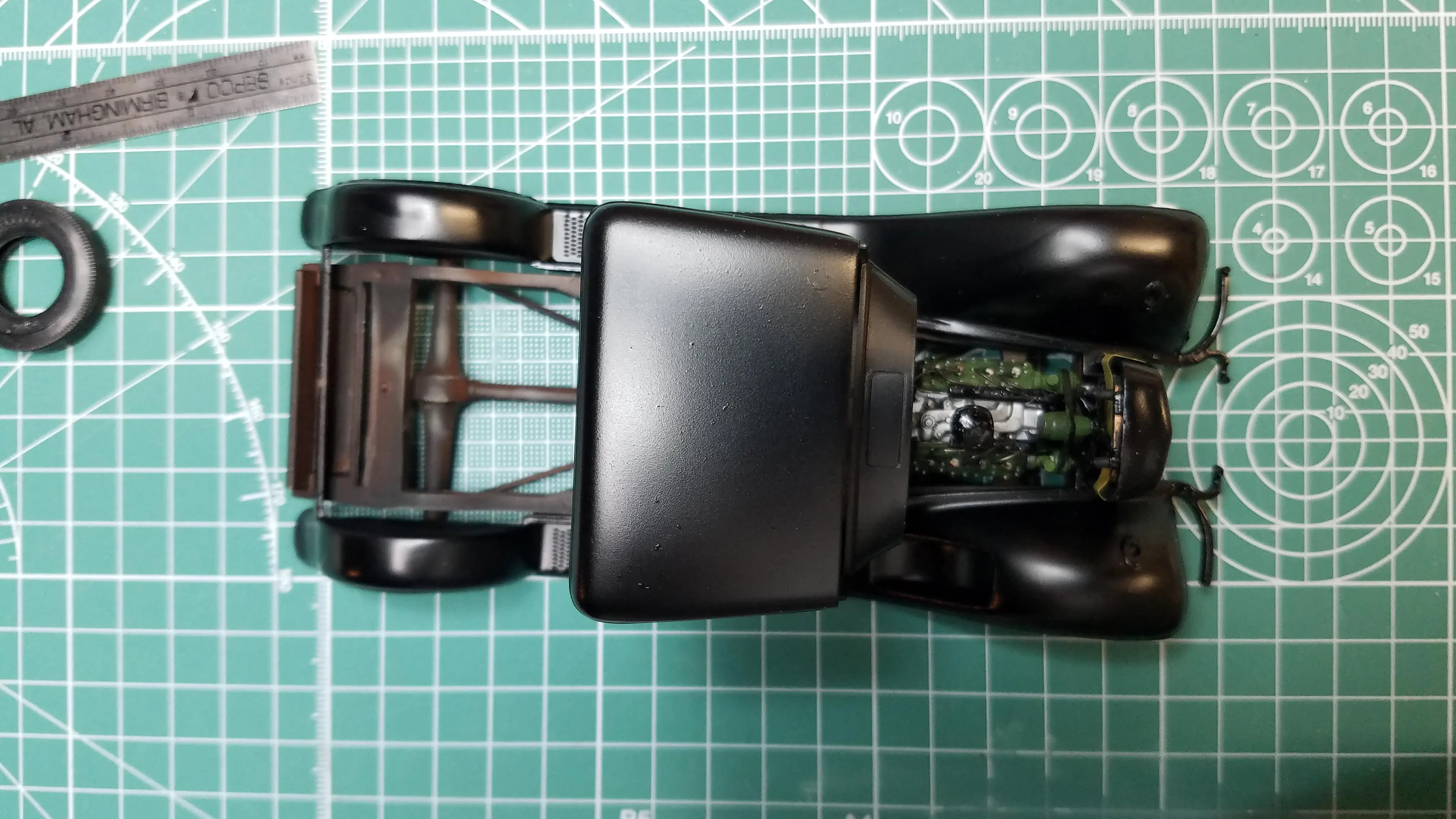 Dry fitting body and chassis
 Truck bed being dry fitted
 Dry fitting body parts
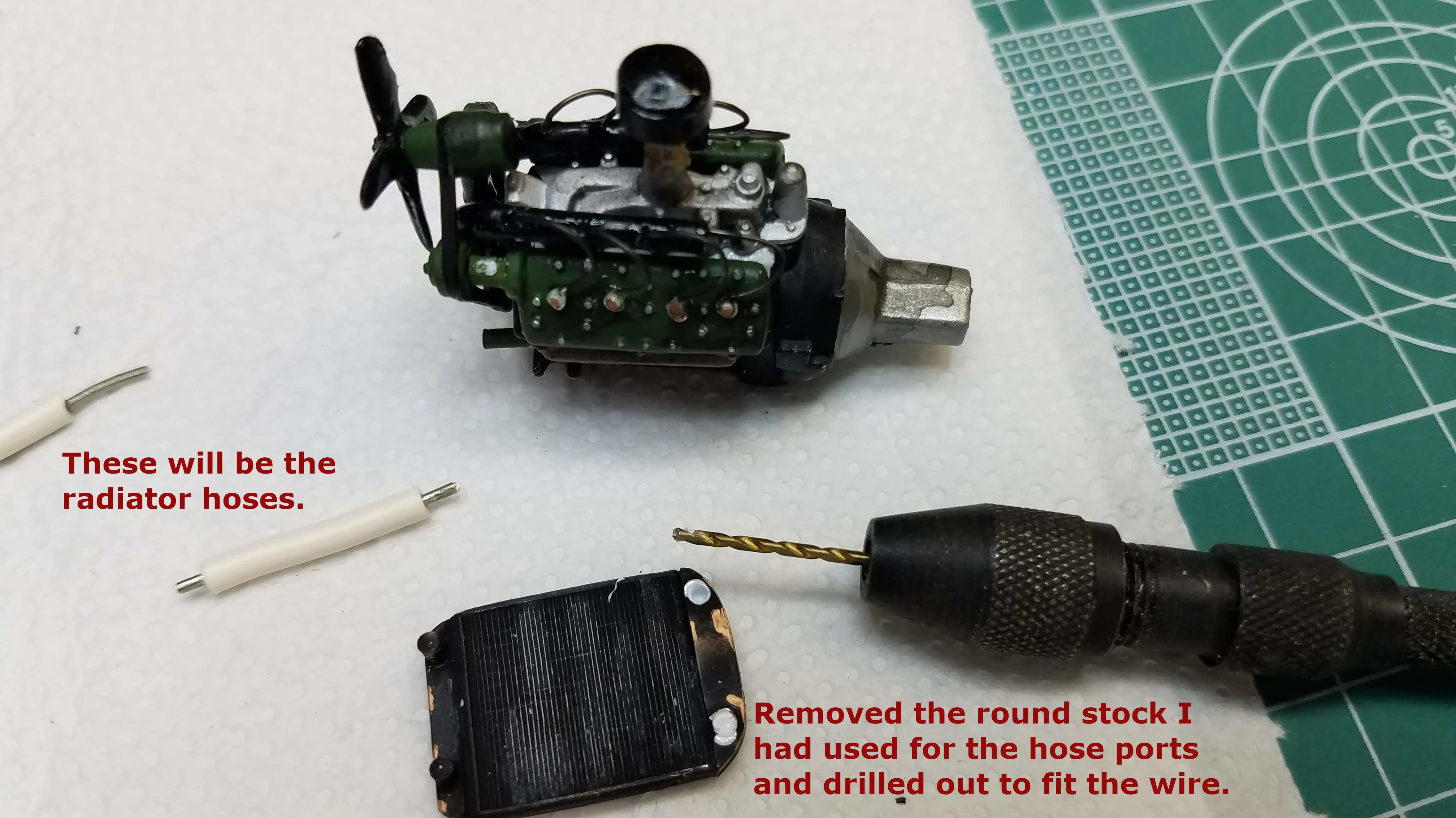 Making radiator hoses
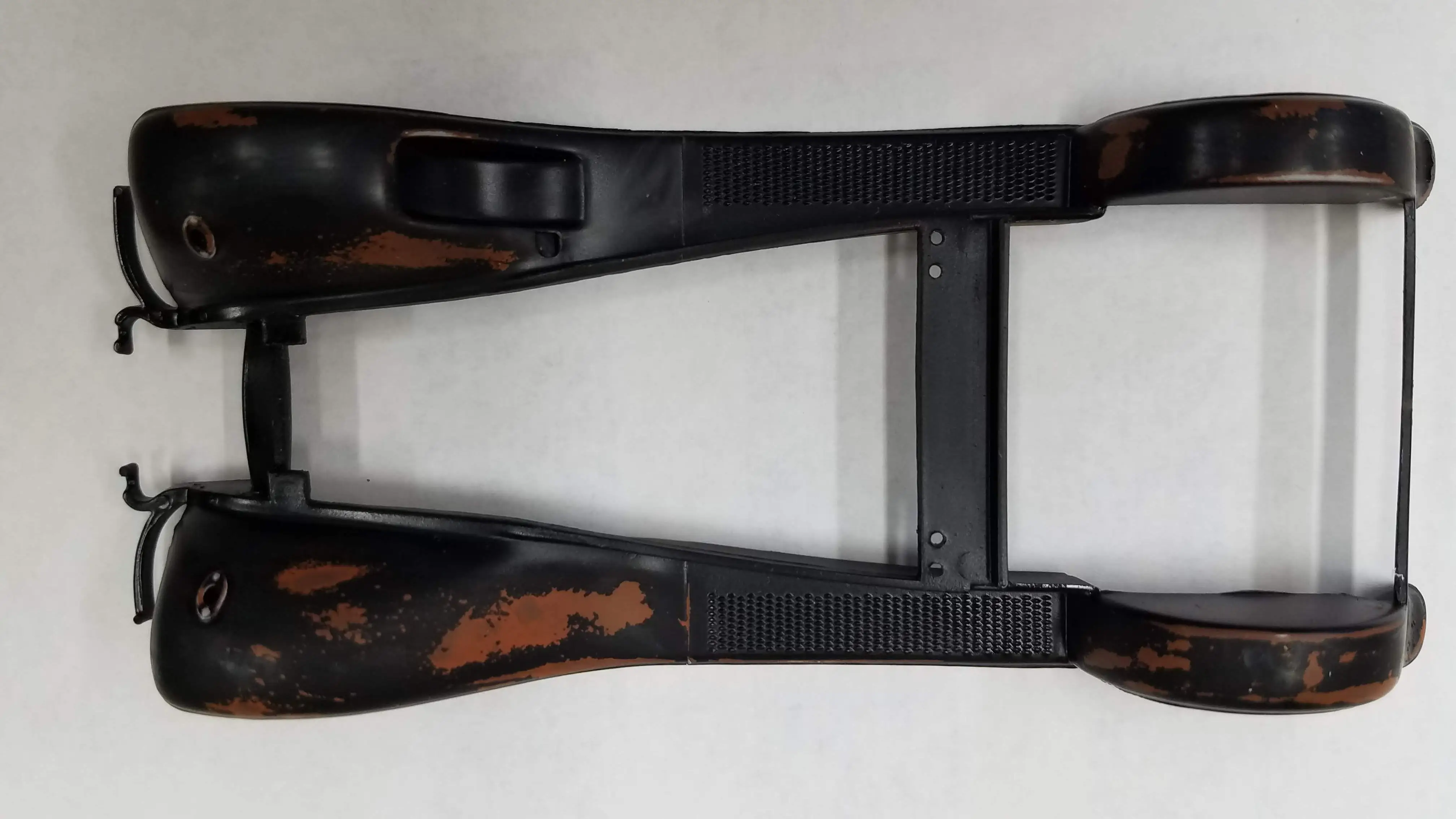 Sanding fenders to show rust
 Sanding fenders to show rust
 Chipping and scratching the cab
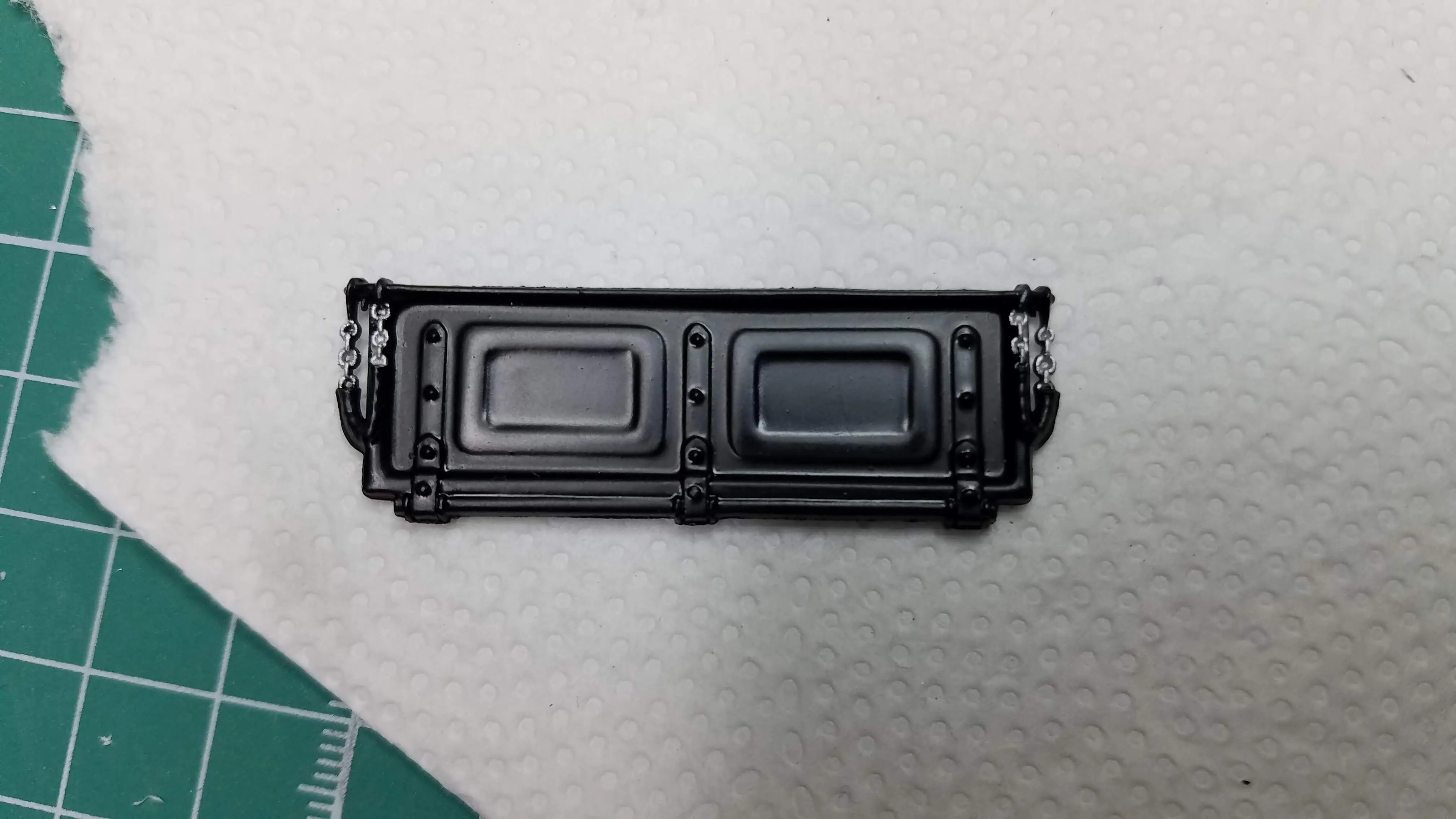 Tailgate chains painted
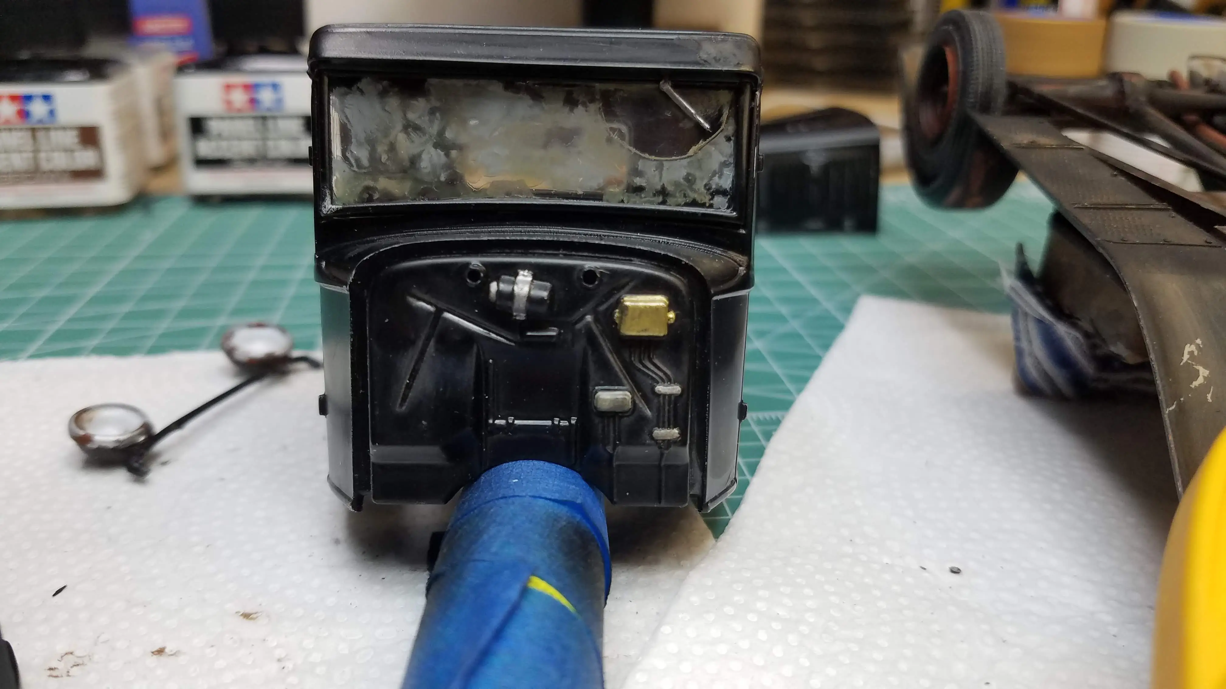
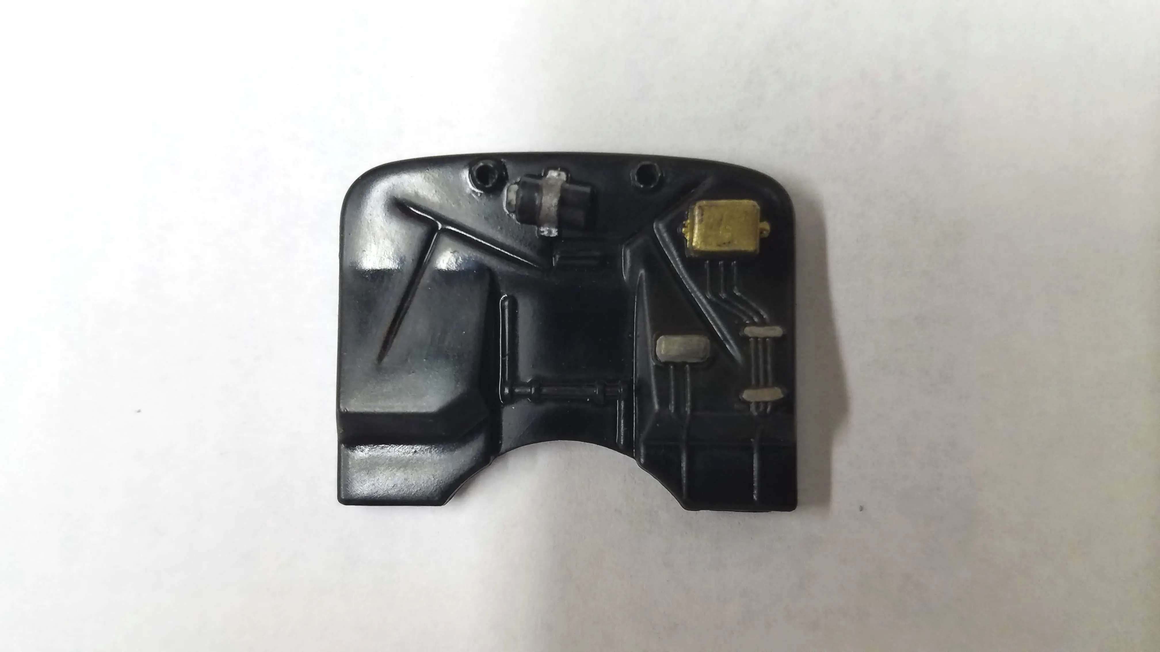 Firewall detailed
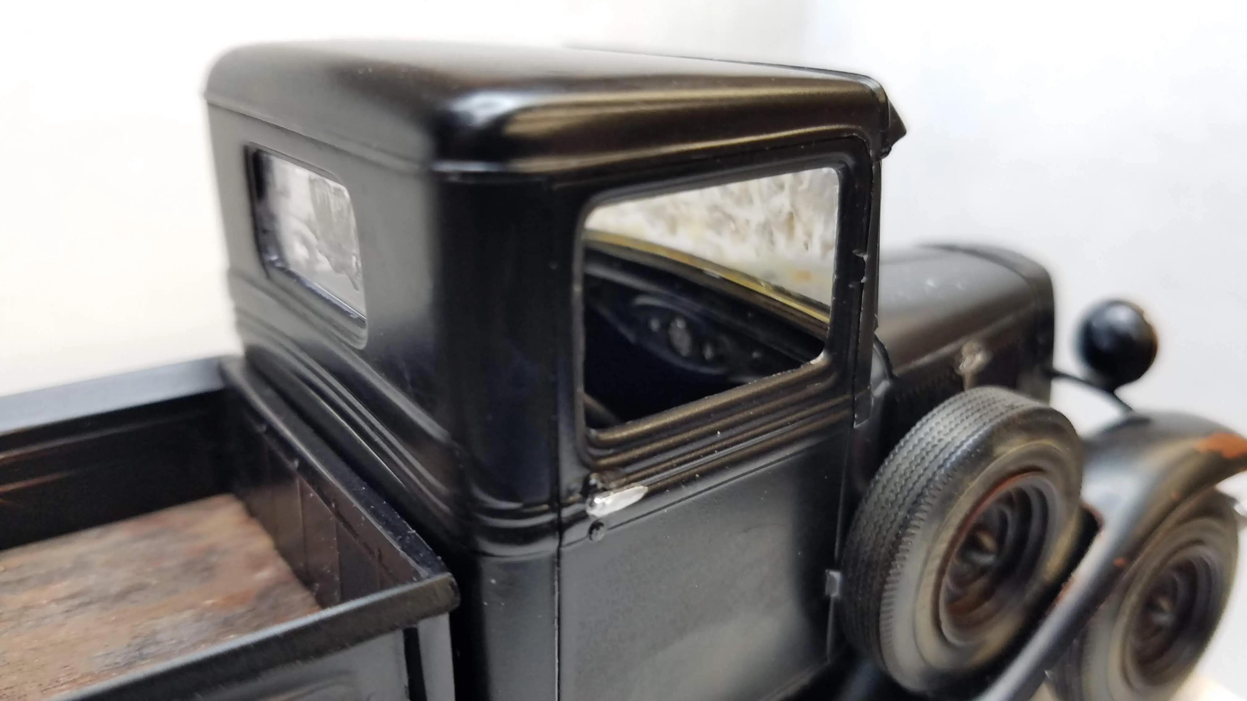
 Car interior is finished
 Car interior is finished
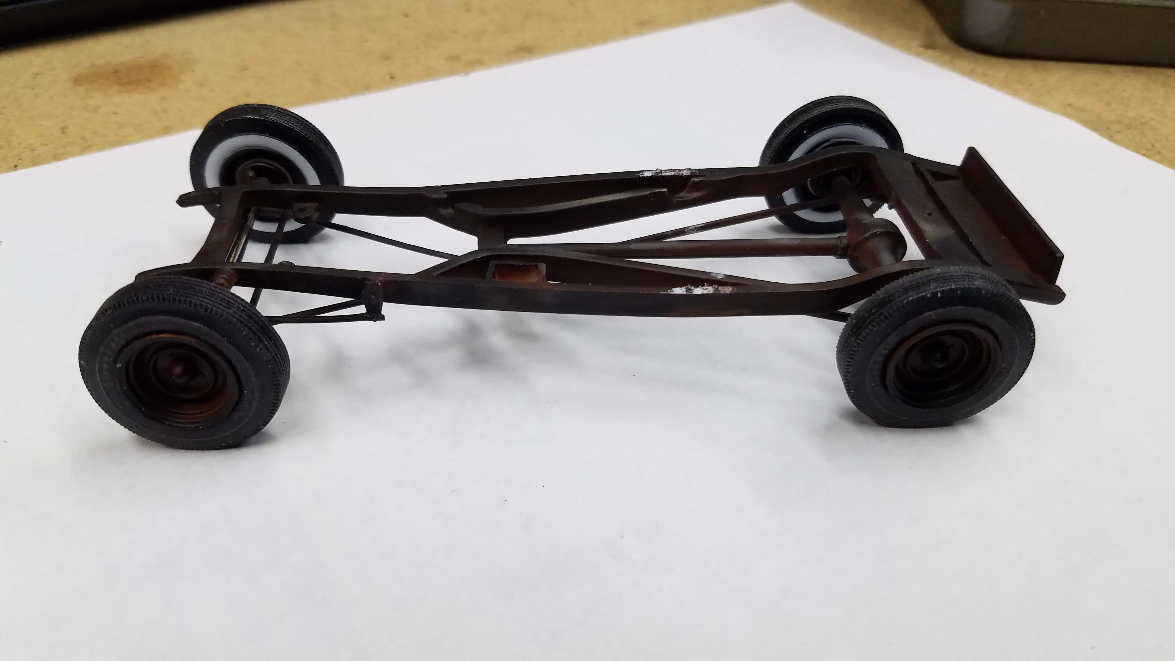 Wheels and tires installed on the frame
 Frame installed in the chassis
 Frame installed in the chassis
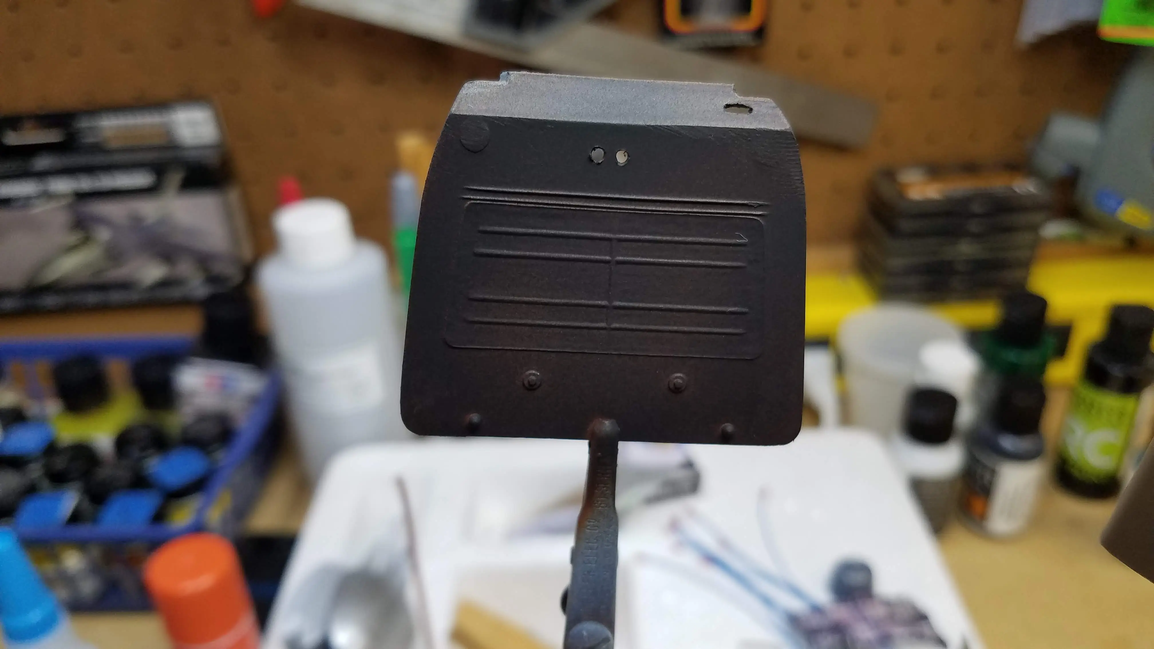
 Tailgate and radiator housing dirtied and scratched
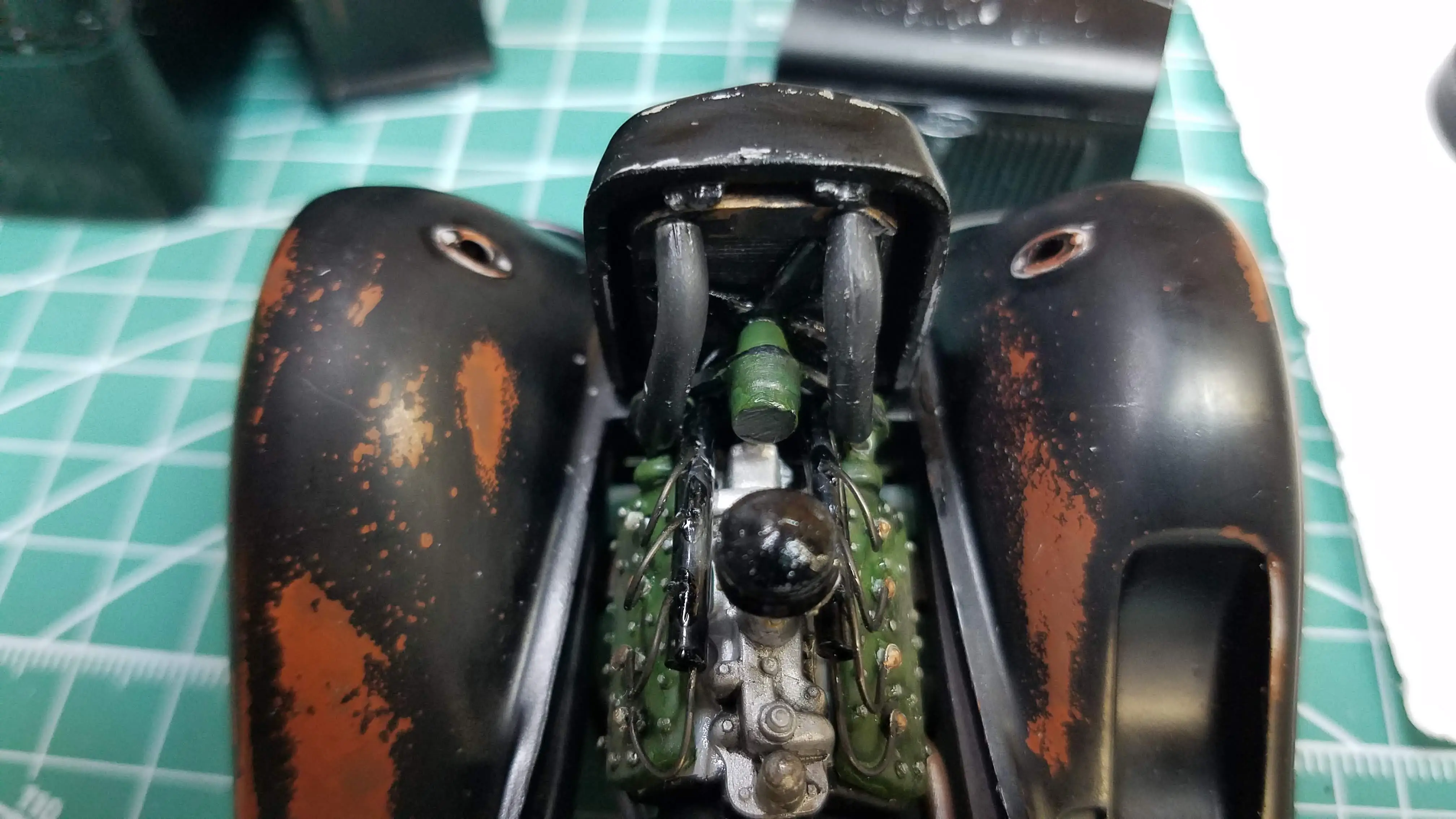
 Engine and interior mounted on chassis/frame
 Engine and interior mounted on chassis/frame
 Engine and interior mounted on chassis/frame
 Dashboard and firewall installed, windshield dirtied
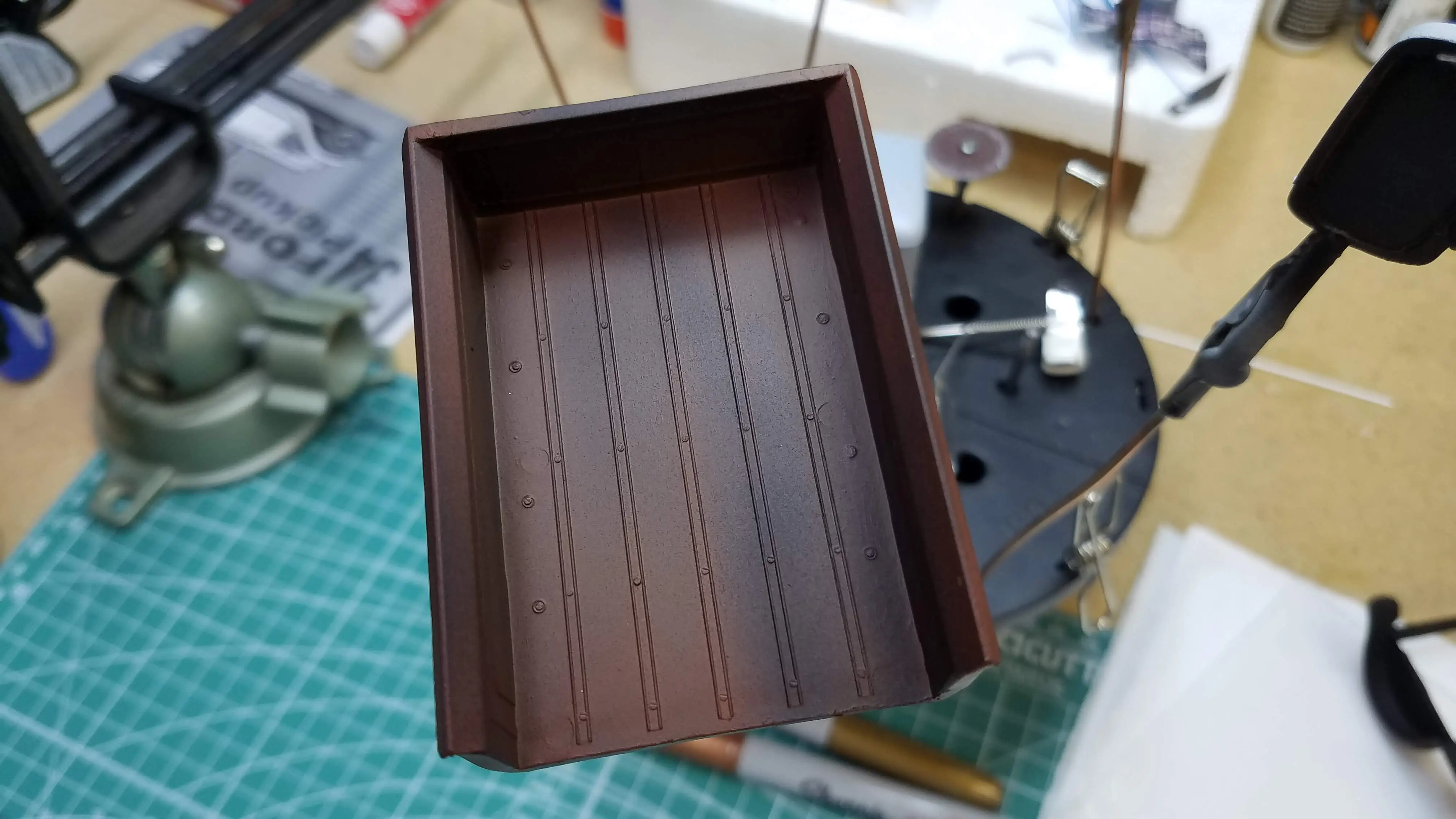
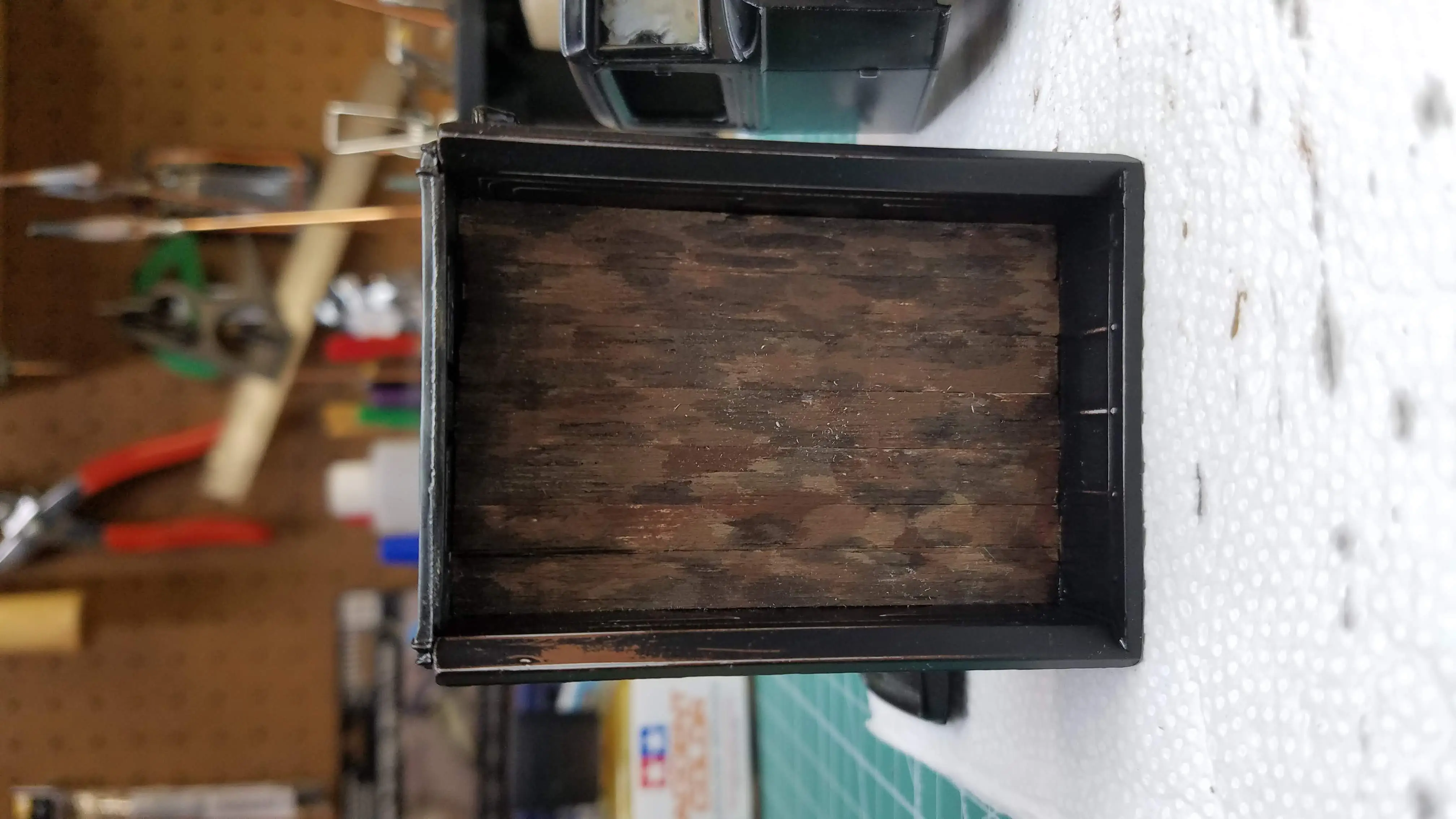 Wood bed installed in the truck bed and dirtied
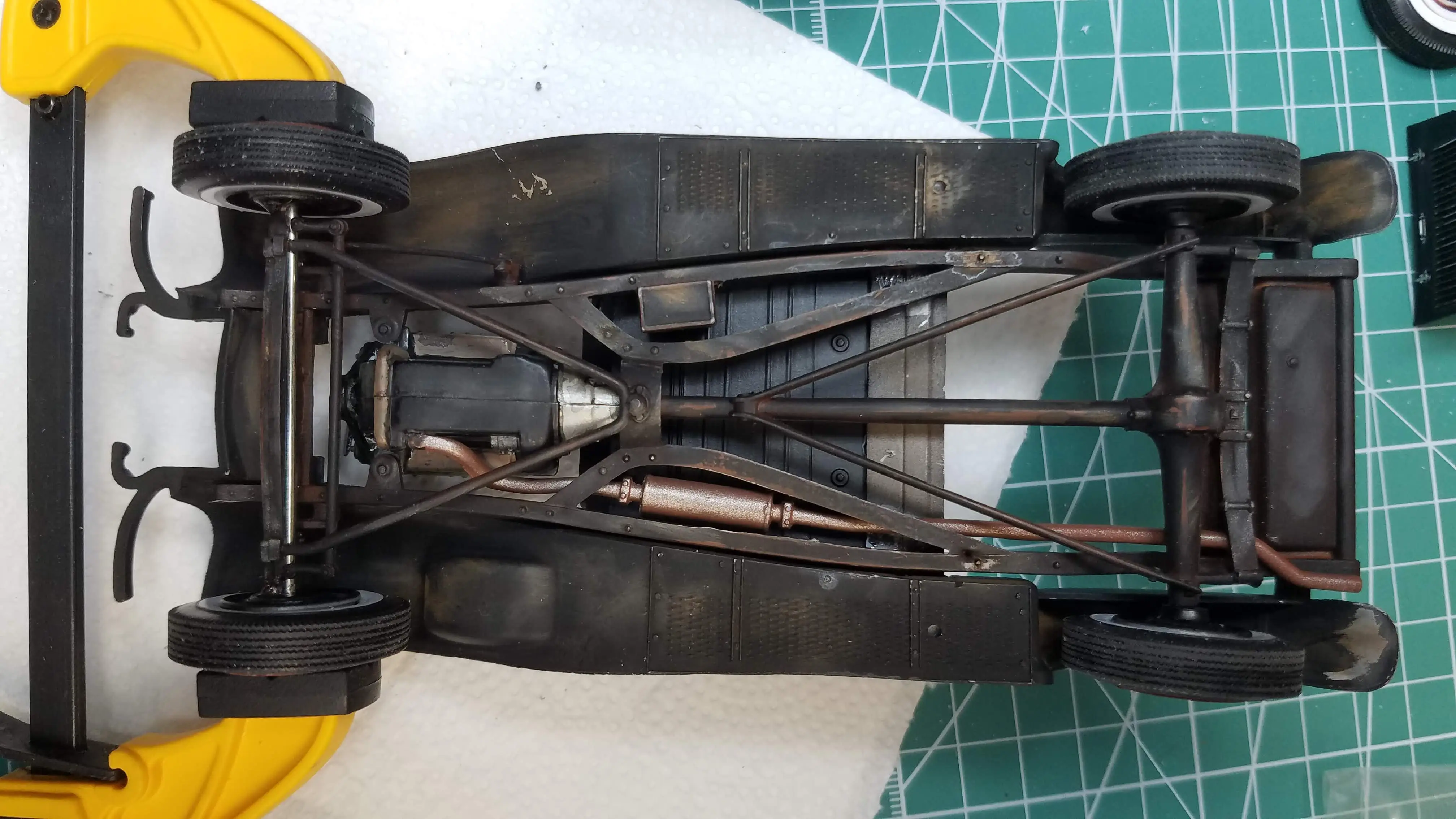 Exhaust pipe and muffler and more underside dirtying
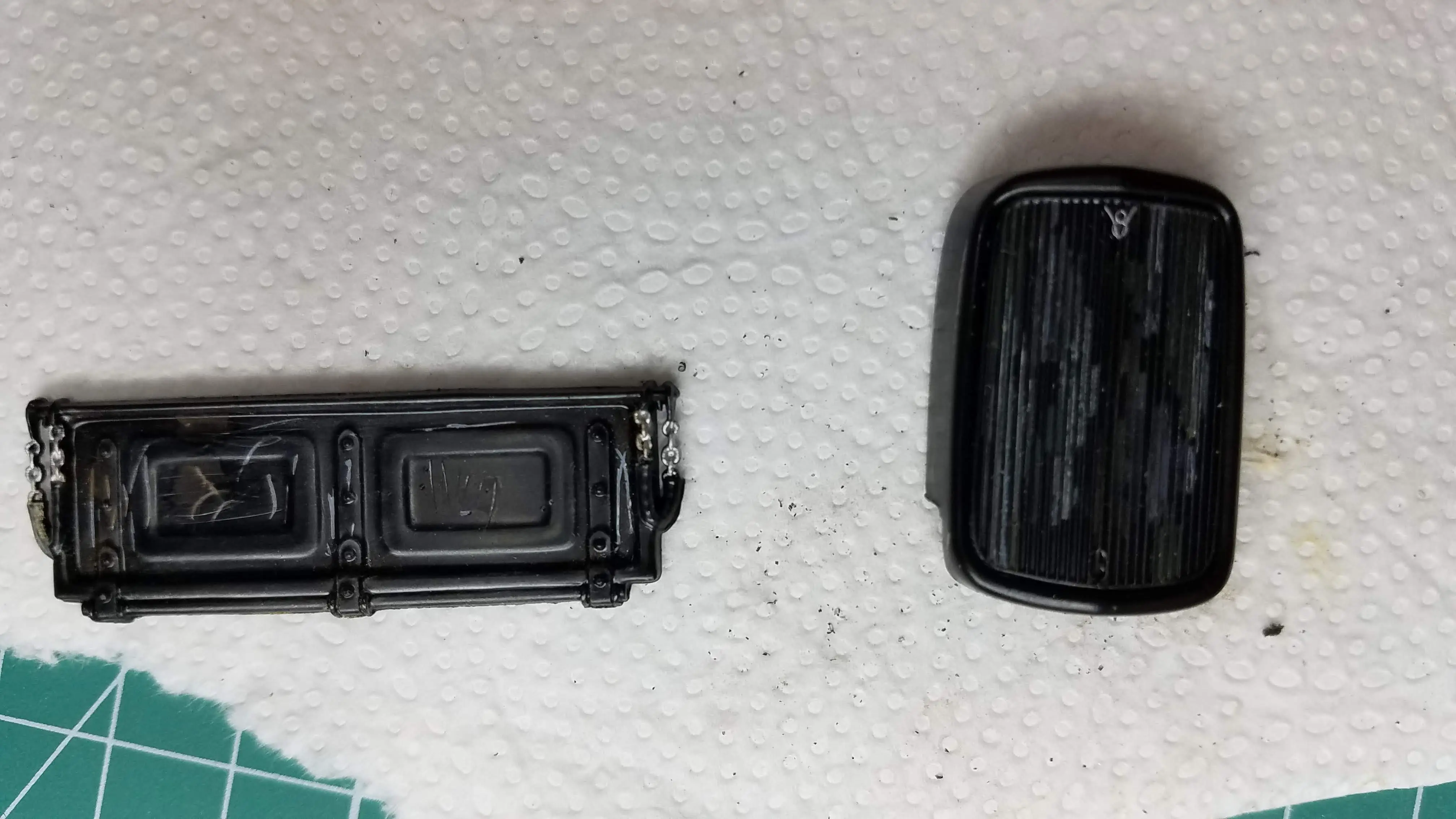
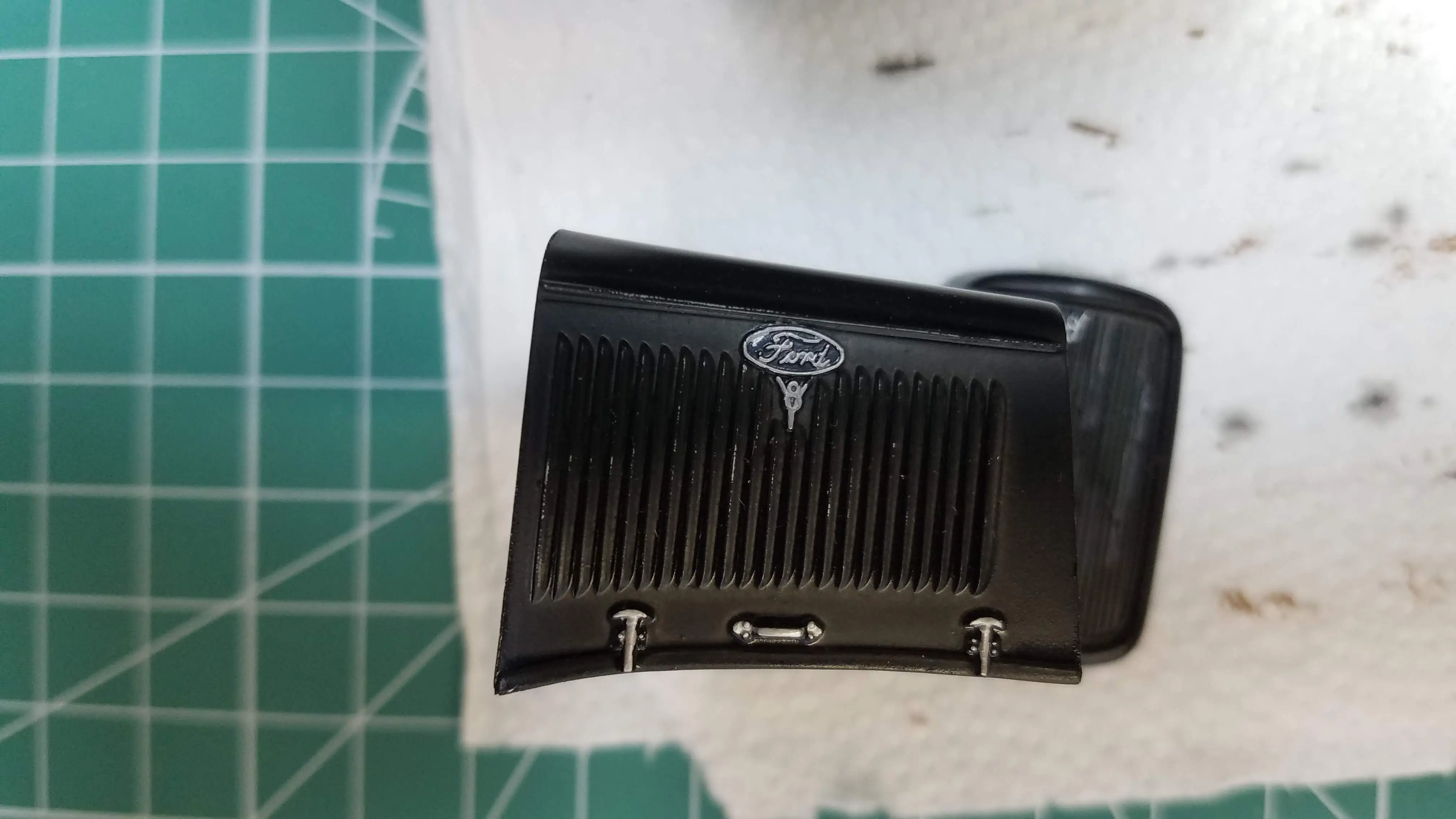
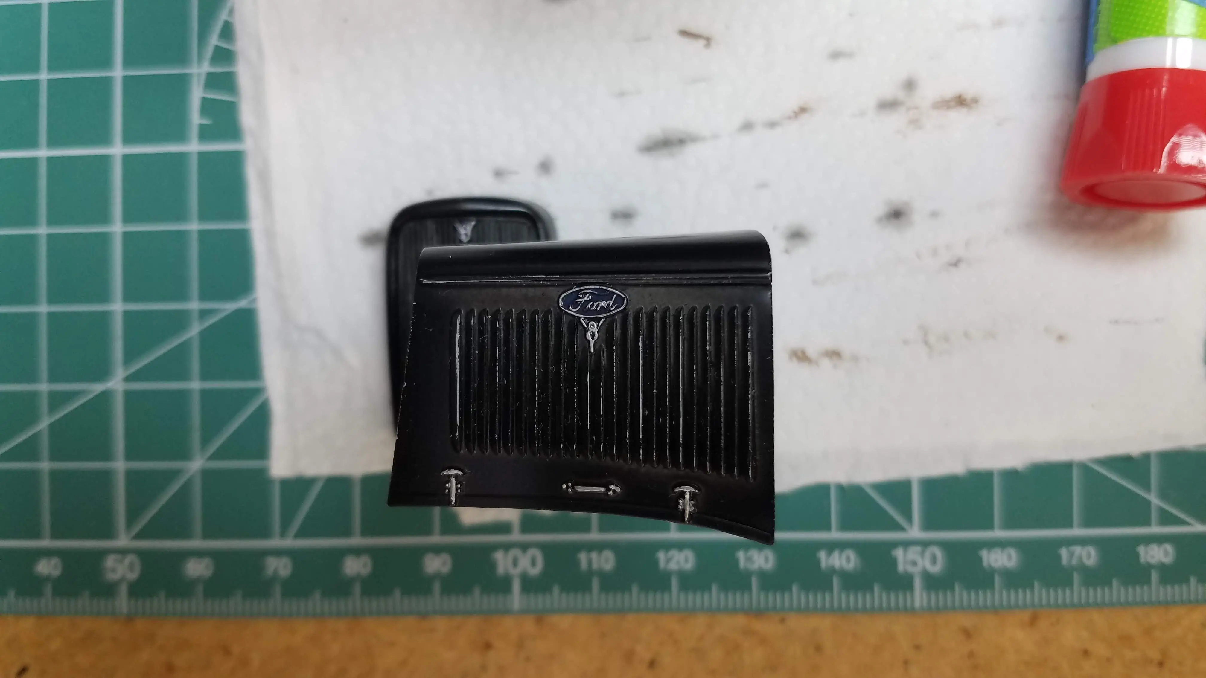 Engine shroud detailed and Ford logo painted and filled
 Engine shroud detailed and Ford logo painted and filled
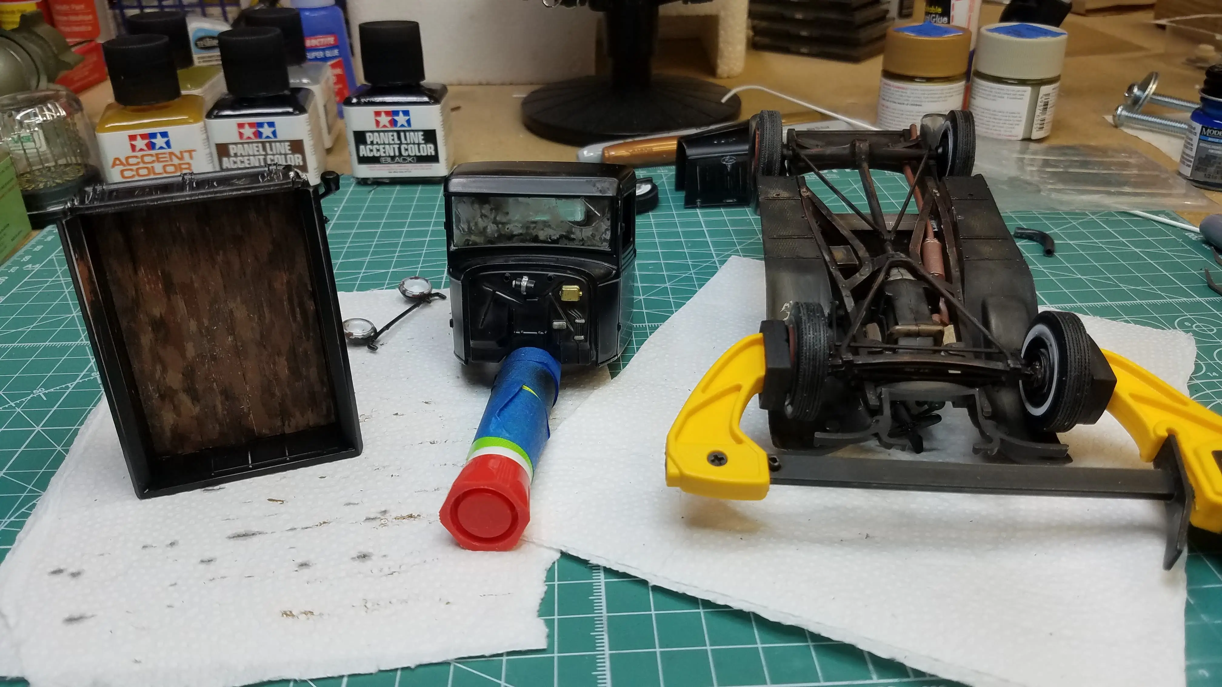 Truck bed, cab and frame/chassis assembly need to be assembled
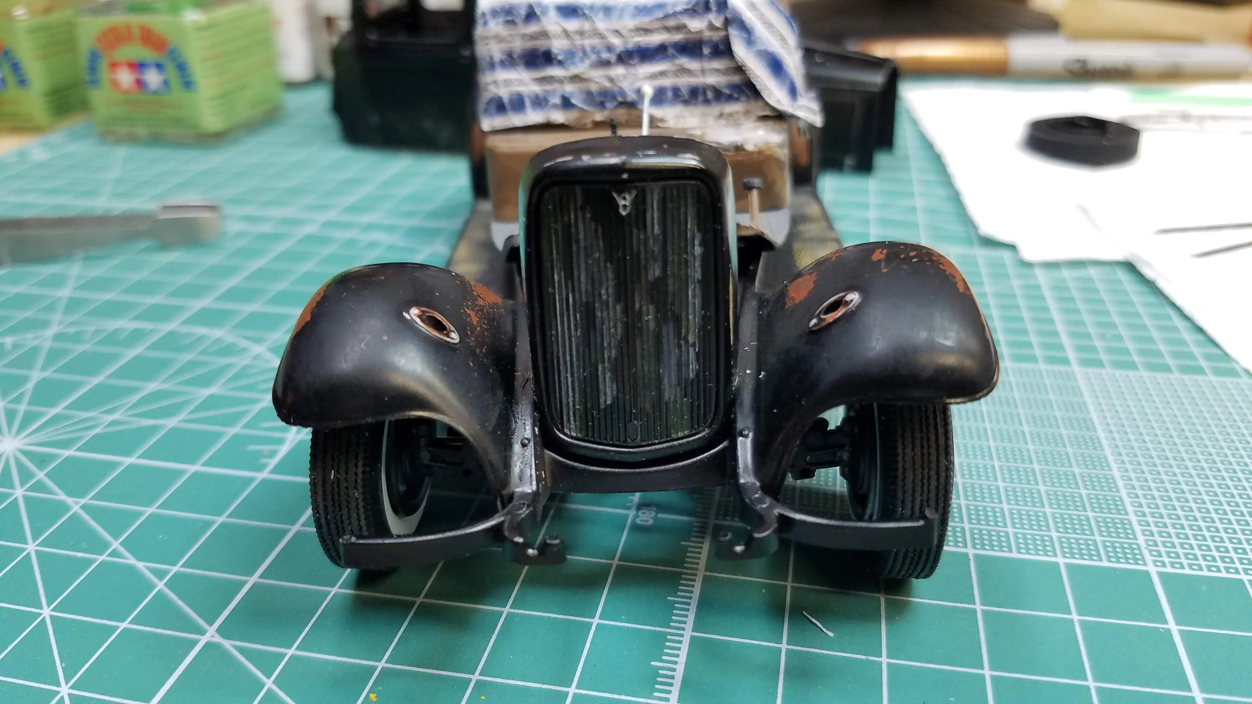 Radiator shroud installed
 Upper radiator hoses installed
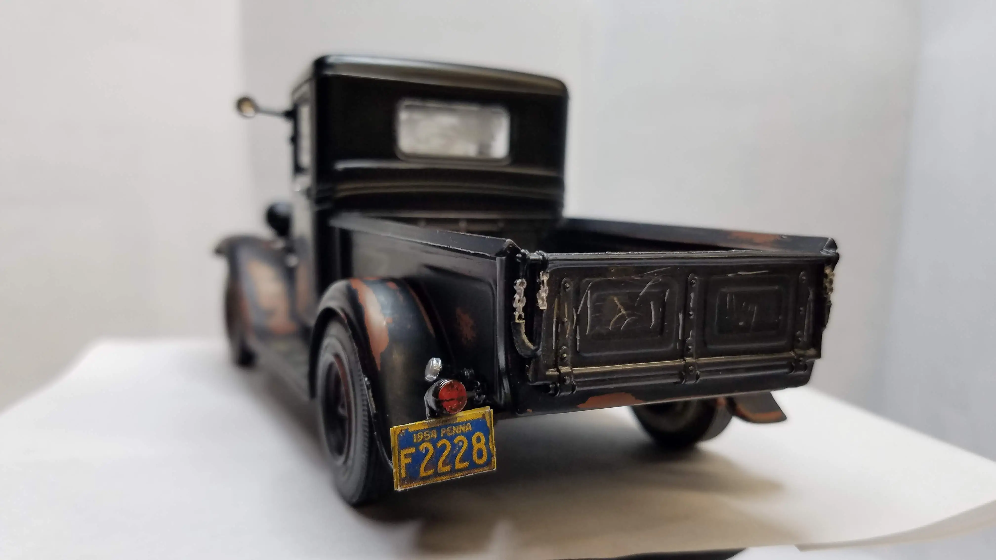
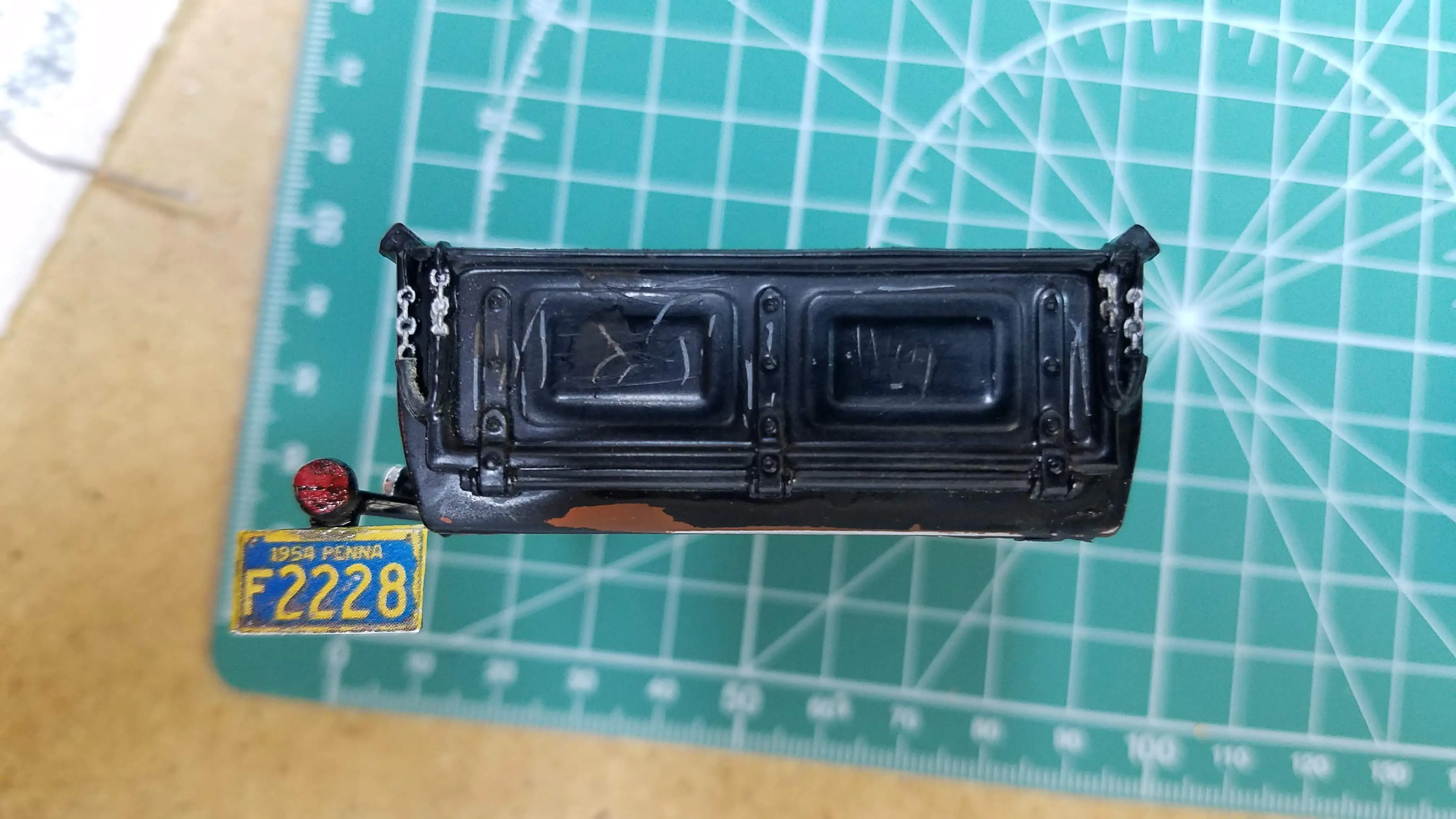 License plate holder and PA license plate added
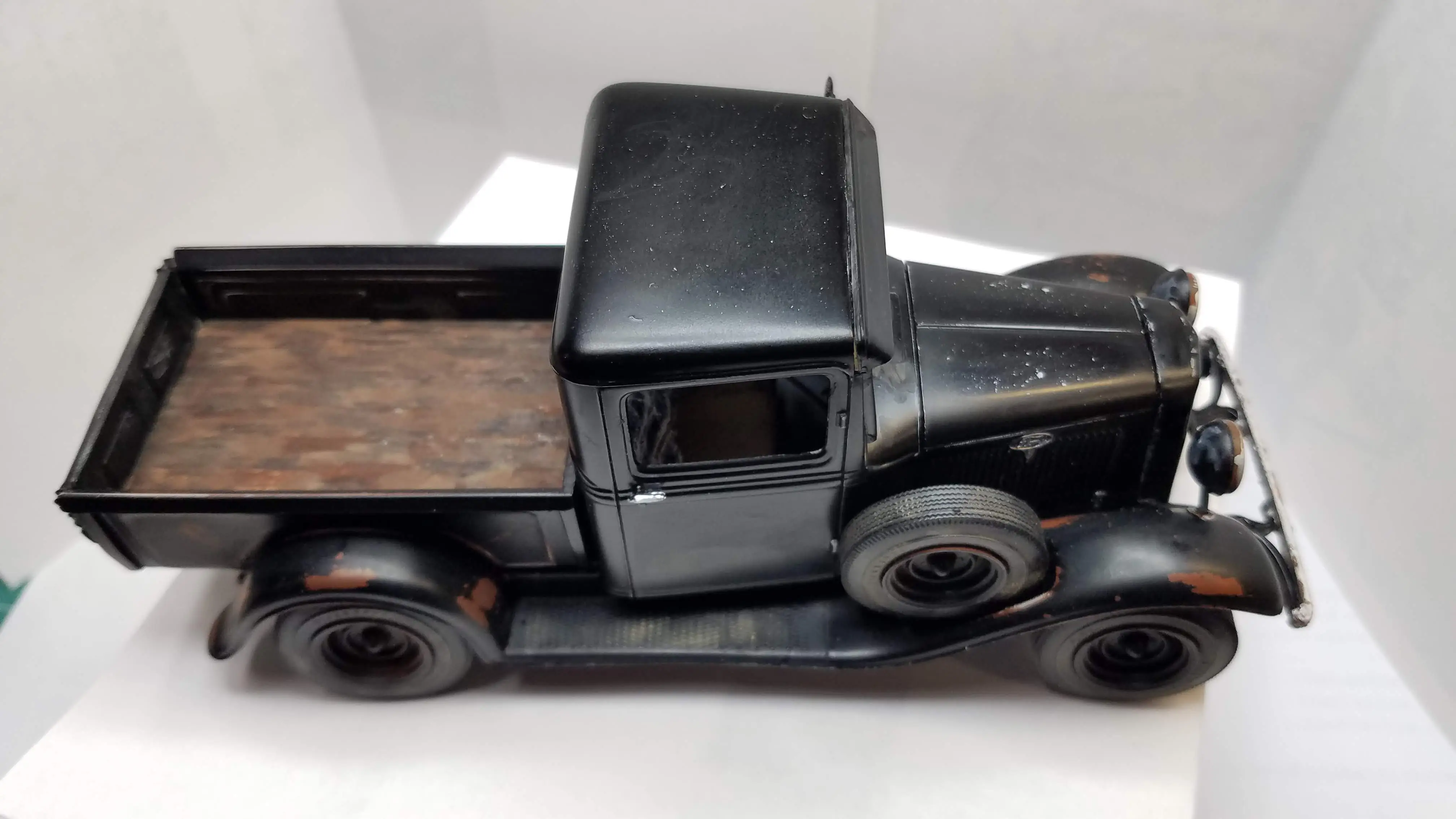
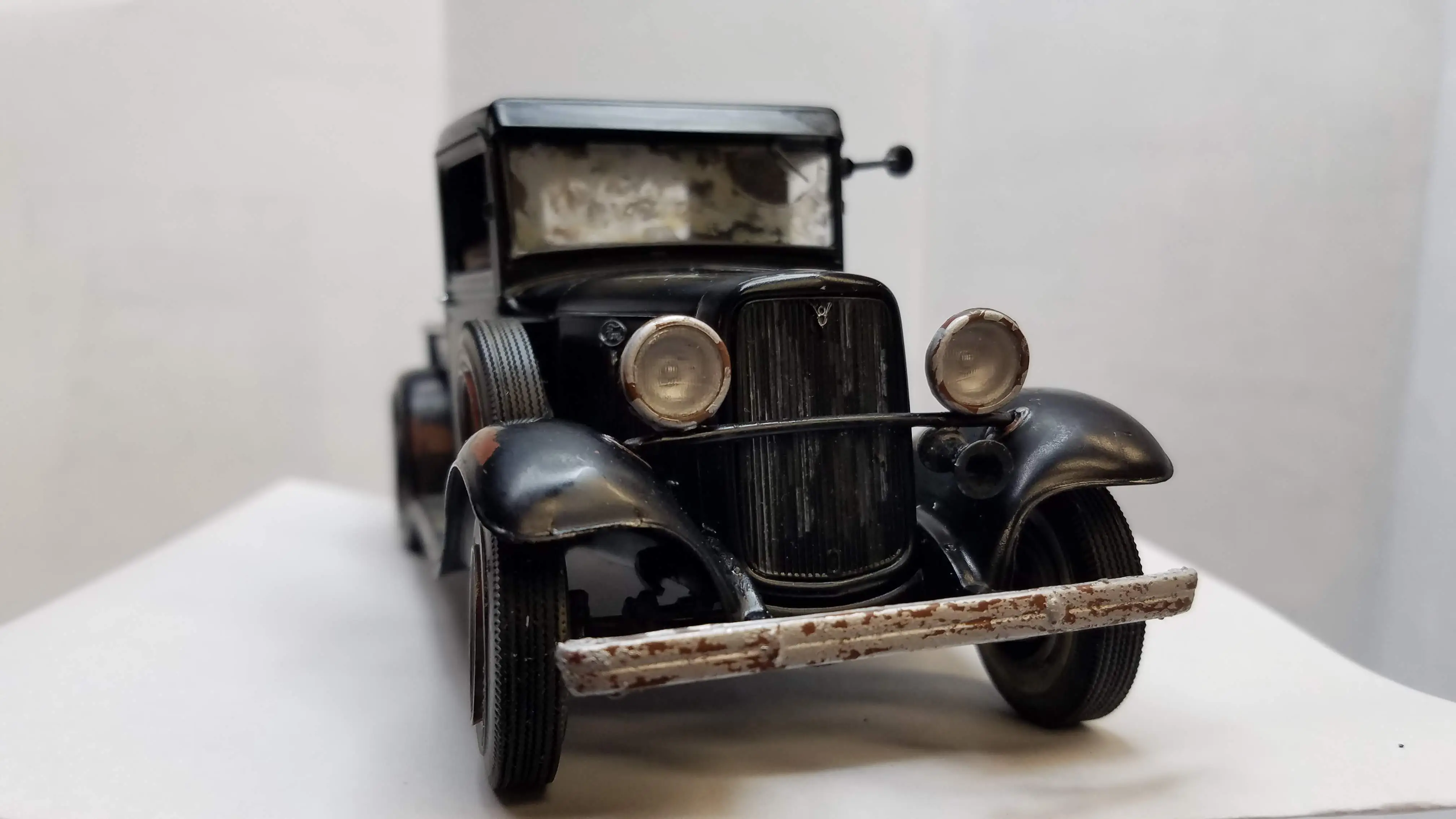
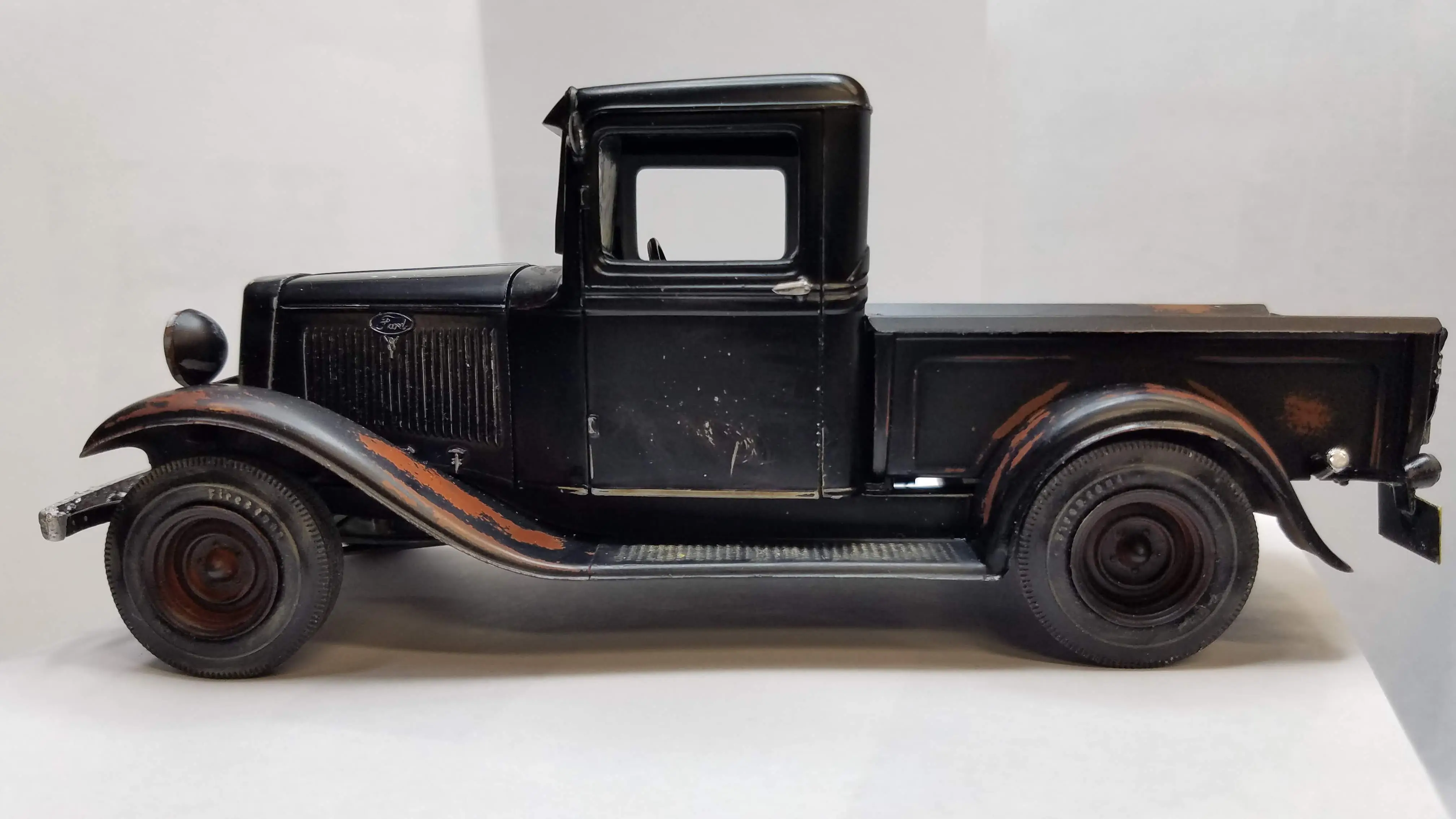 Finished build
 Finished build
 Finished build
 Finished build
 Finished build
 Finished build
 COMING SOON
Finished build
COMING SOON
Finished build
 Finished build
 Finished build
 Finished build
 Finished build
 Finished build
 Finished build

