Opening
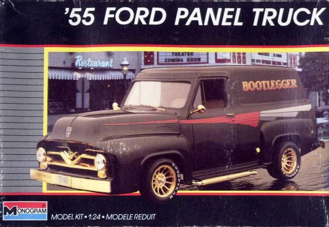
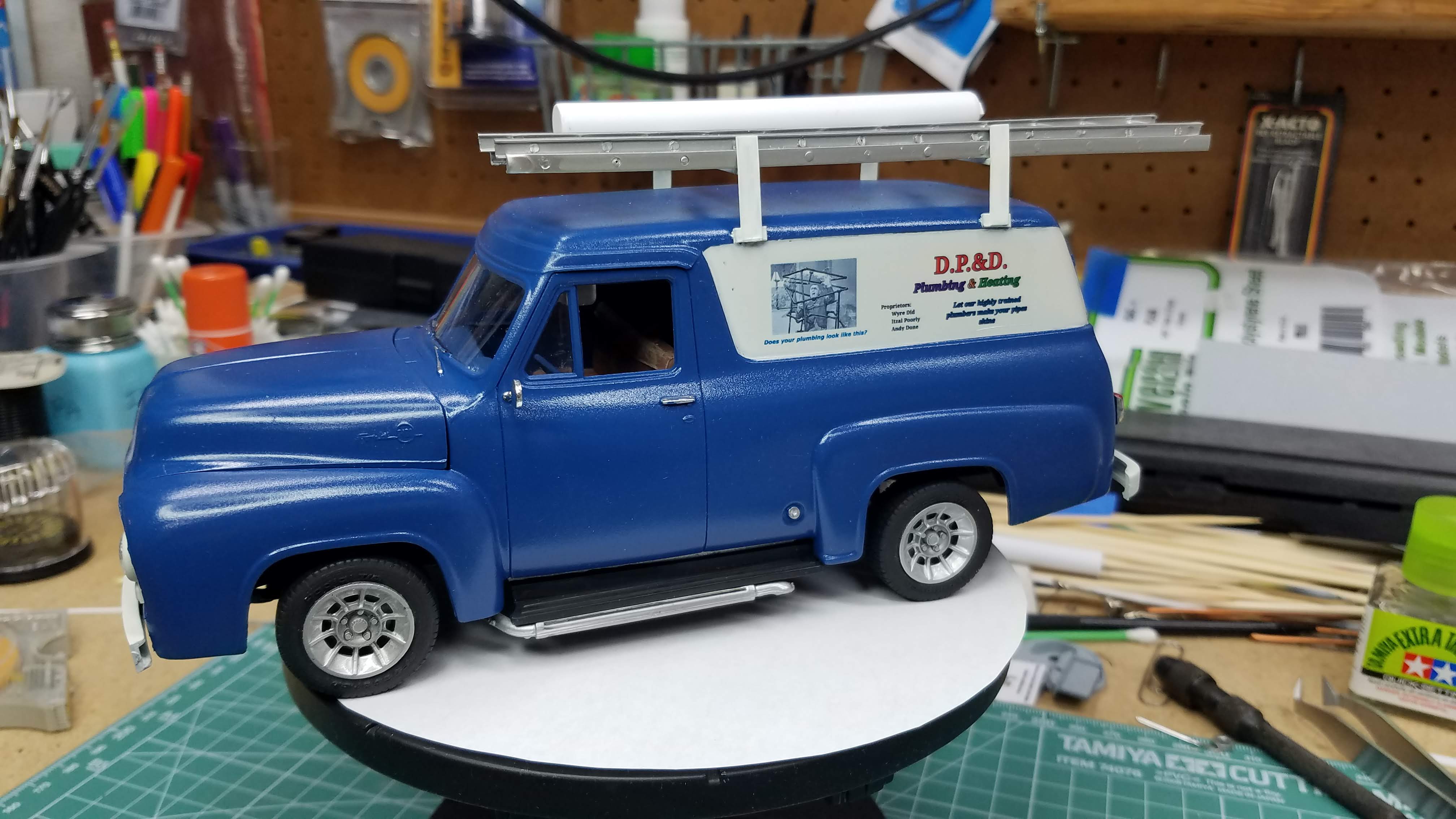
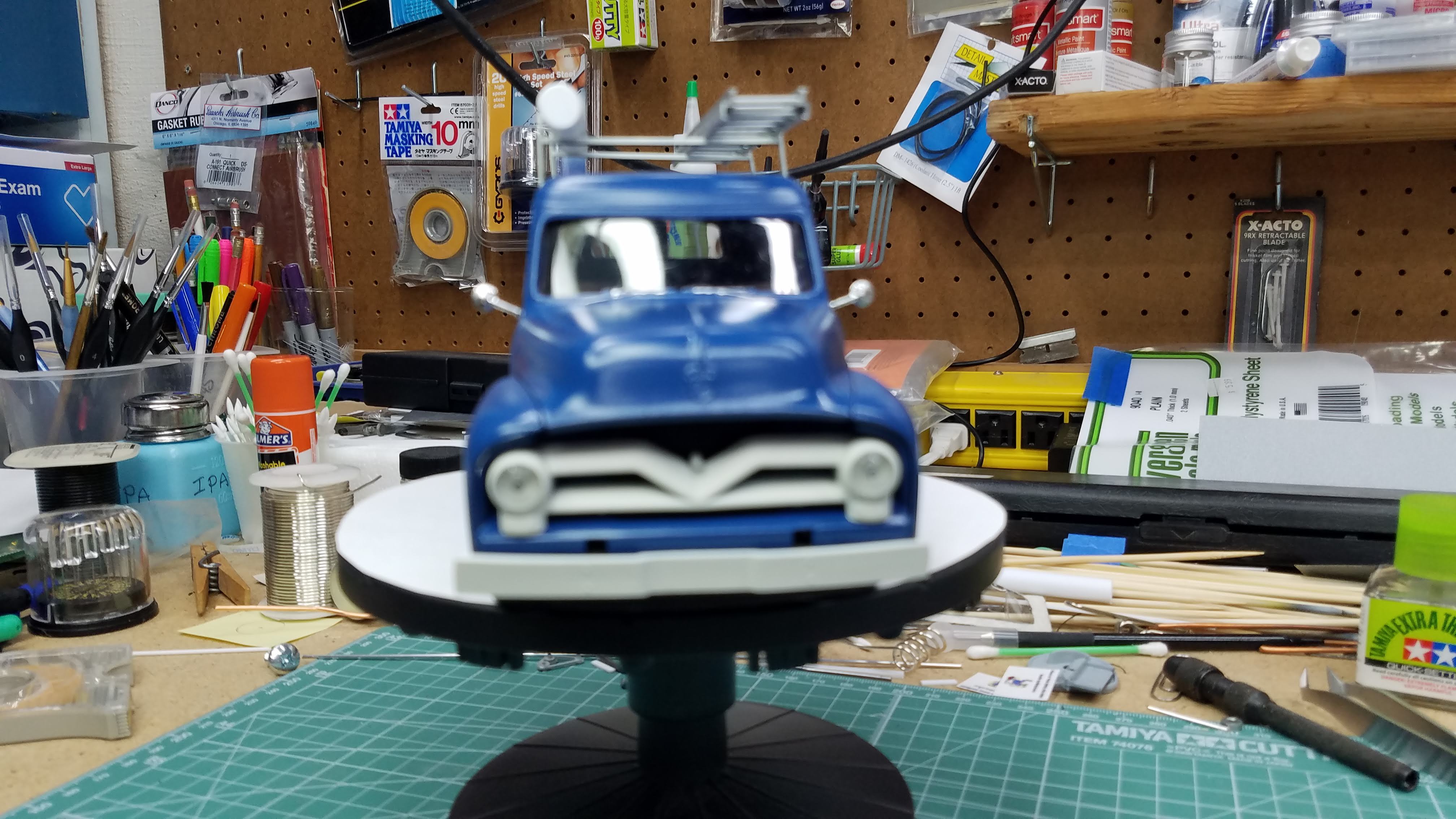
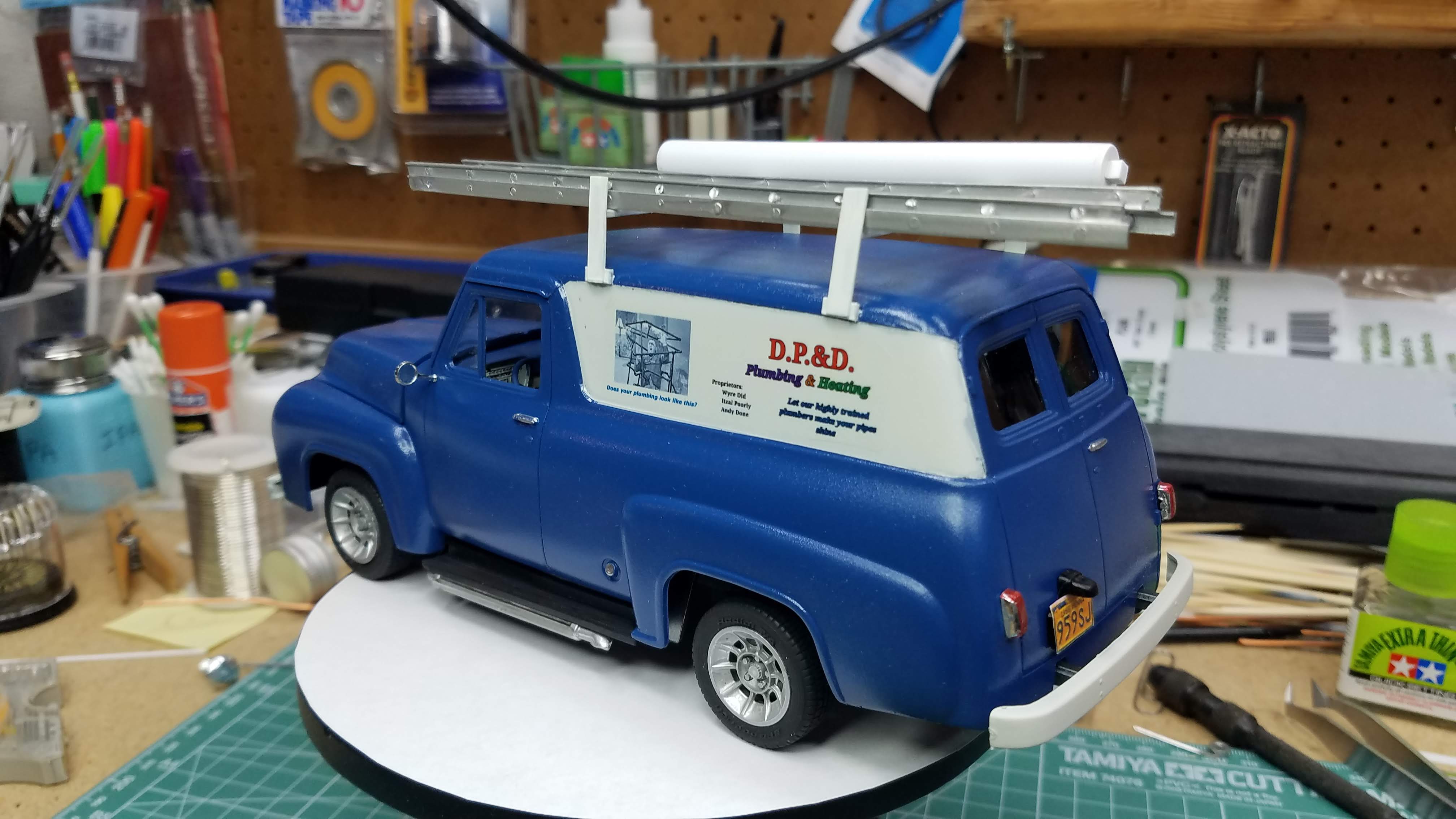
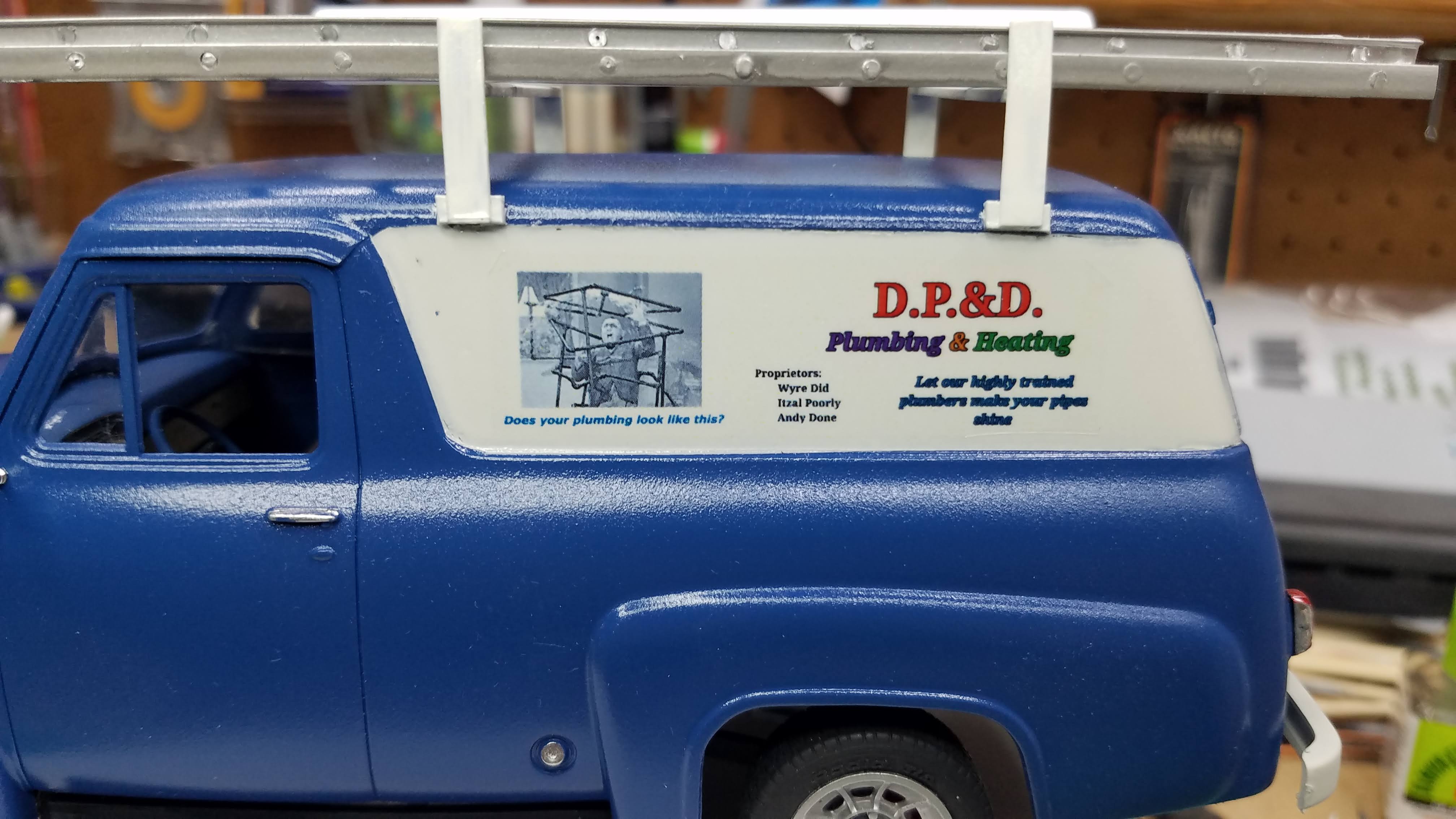
The top picture is the box art for the kit I choose to build for this years Unified Scale Auto Content Creators (USACC) Group Build. The bottom photo is the completed build. Click through the pictures to view a photo journal of the build process I used.
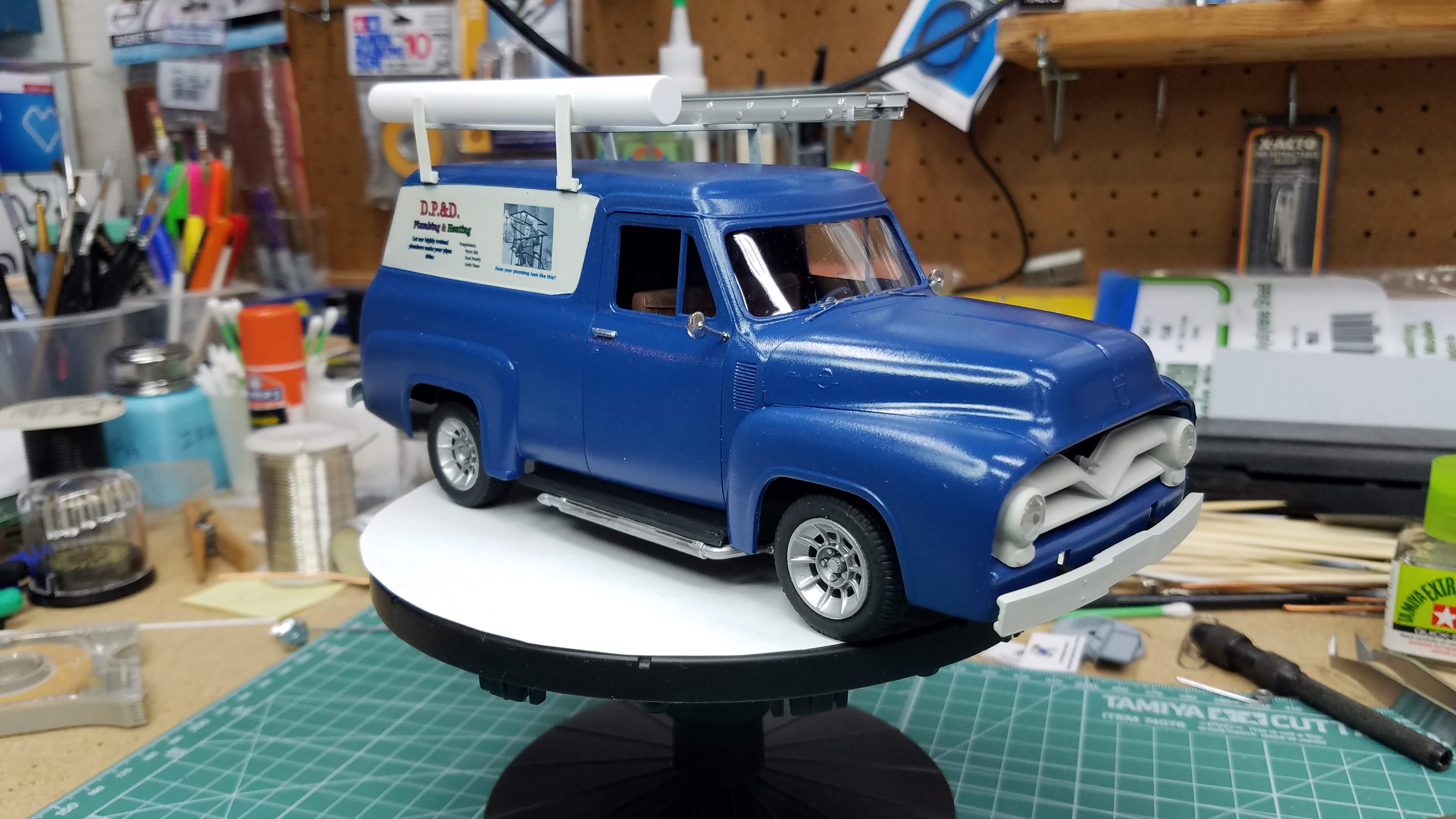
I made it a utility van for a plumbing business; however, the plumbing business is only a front for the real business. You'll have to wait until the build is complete before you see what the real business is. The last several pictures is an example of what their business really is.
I plan to do a lot of modification to this kit. One of them is that I'll be putting a Chrysler 426 Hemi Engine from a '71 Cuda under the hood. It is/was called the "Elephant Engine". I'll be adding roof racks and a 1:24 scale, 24-foot working extension ladder to place on the roof racks. I've already created some custom decals. The Gold grill, mirrors, etc. are being stripped, I'm not crazy about the gold. I will not be using the wheels and tires from the kit, although, the one's I am using are very similar to the boxed wheels and tires.
I'm contemplating opening the back doors and have been experimenting with a hinge design; however, I'm not sure I will do it on this build. You'll see more on the hinge experiment later.
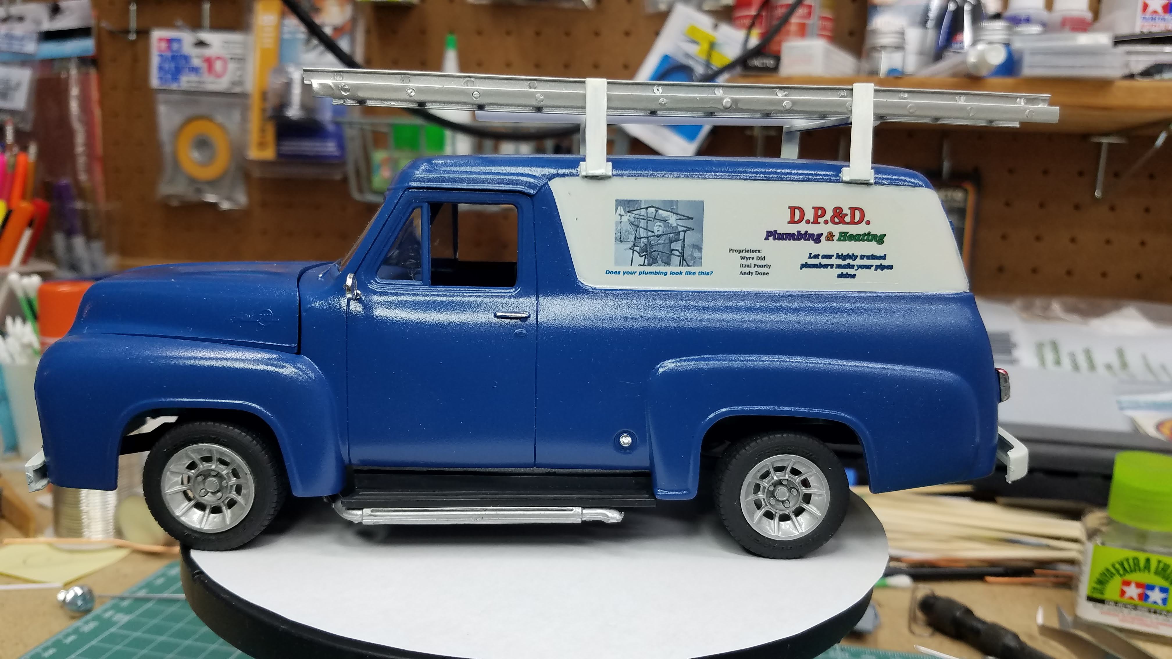
The photo below is the finished build.
1 of 92
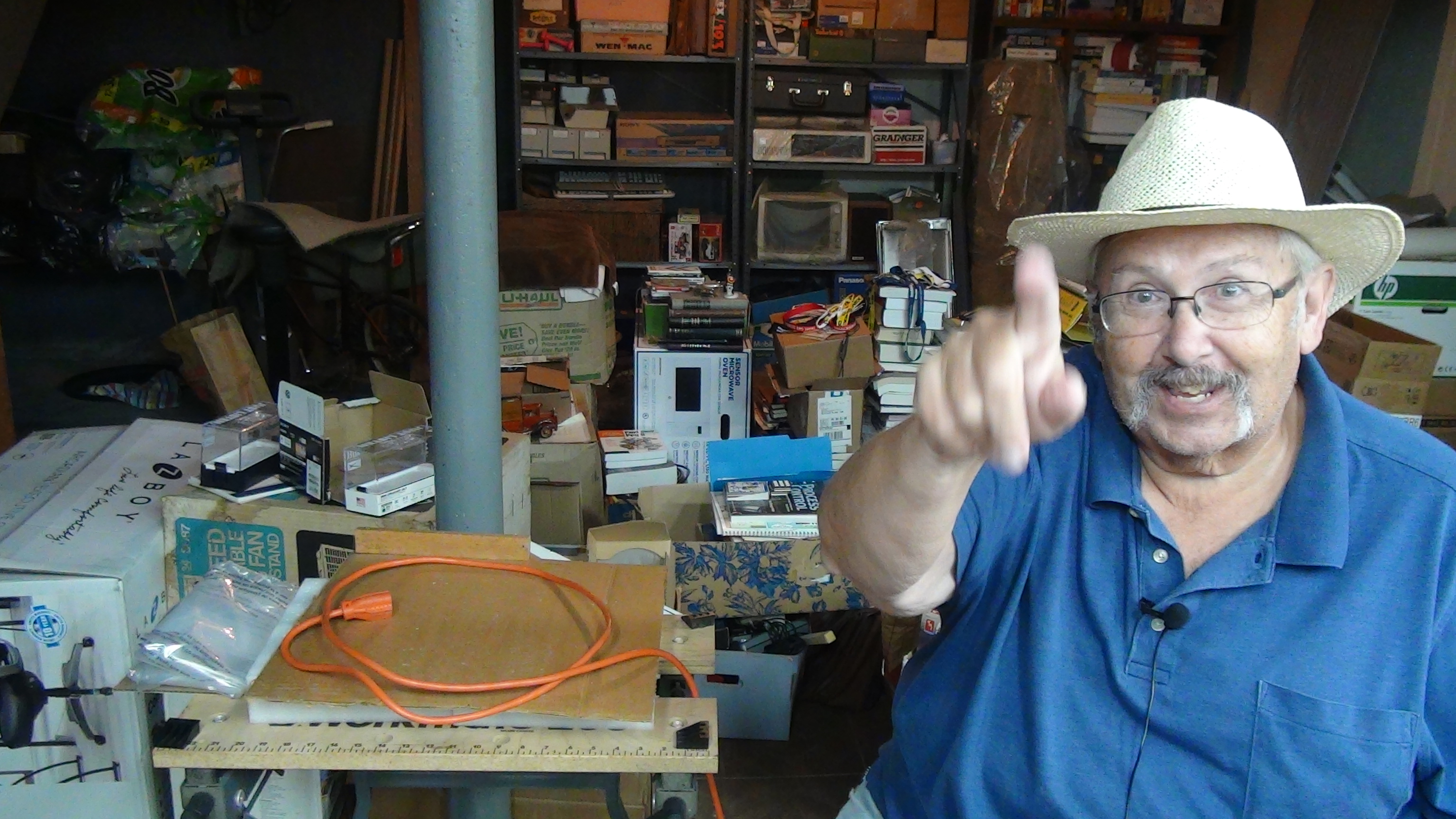
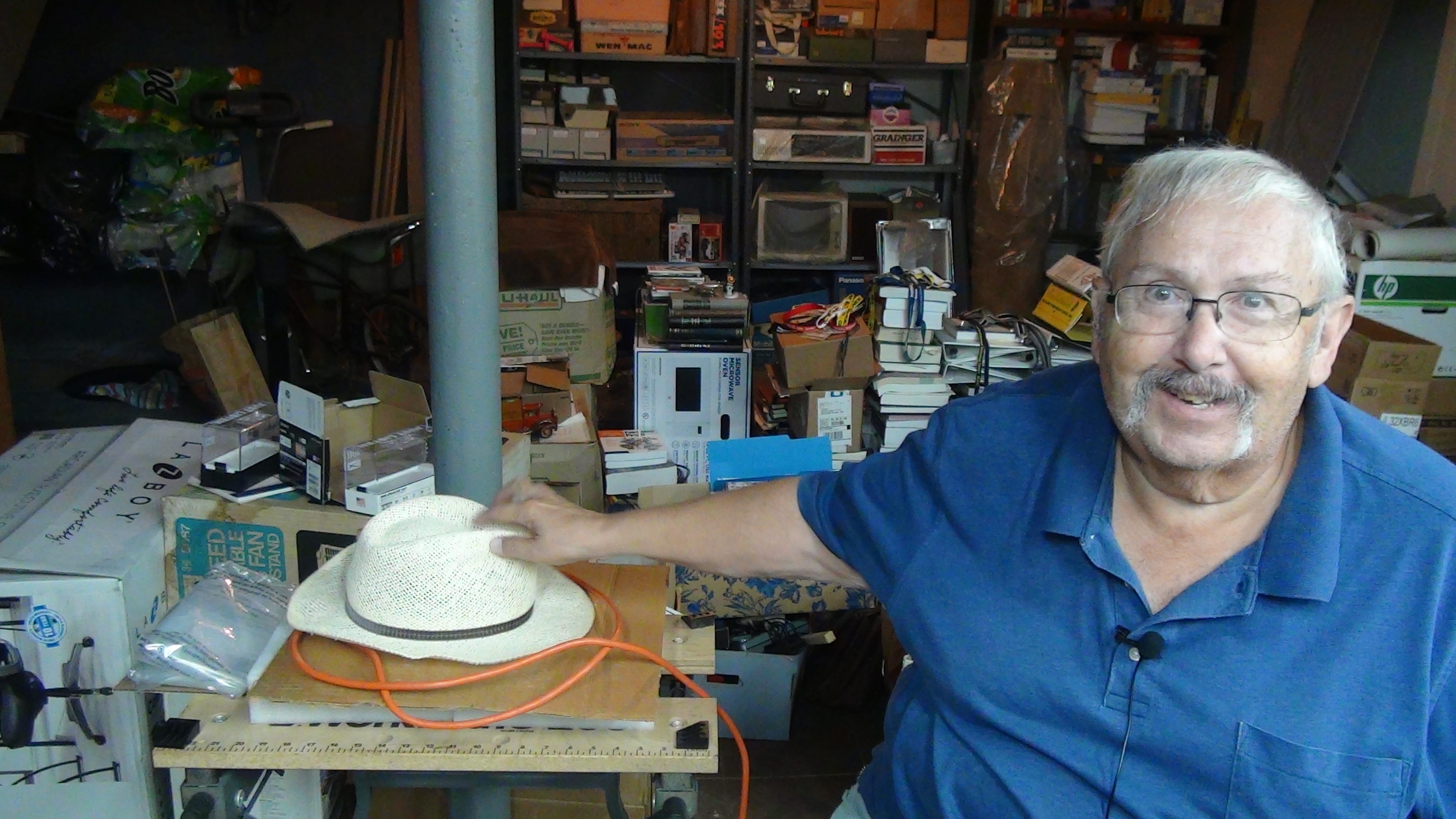
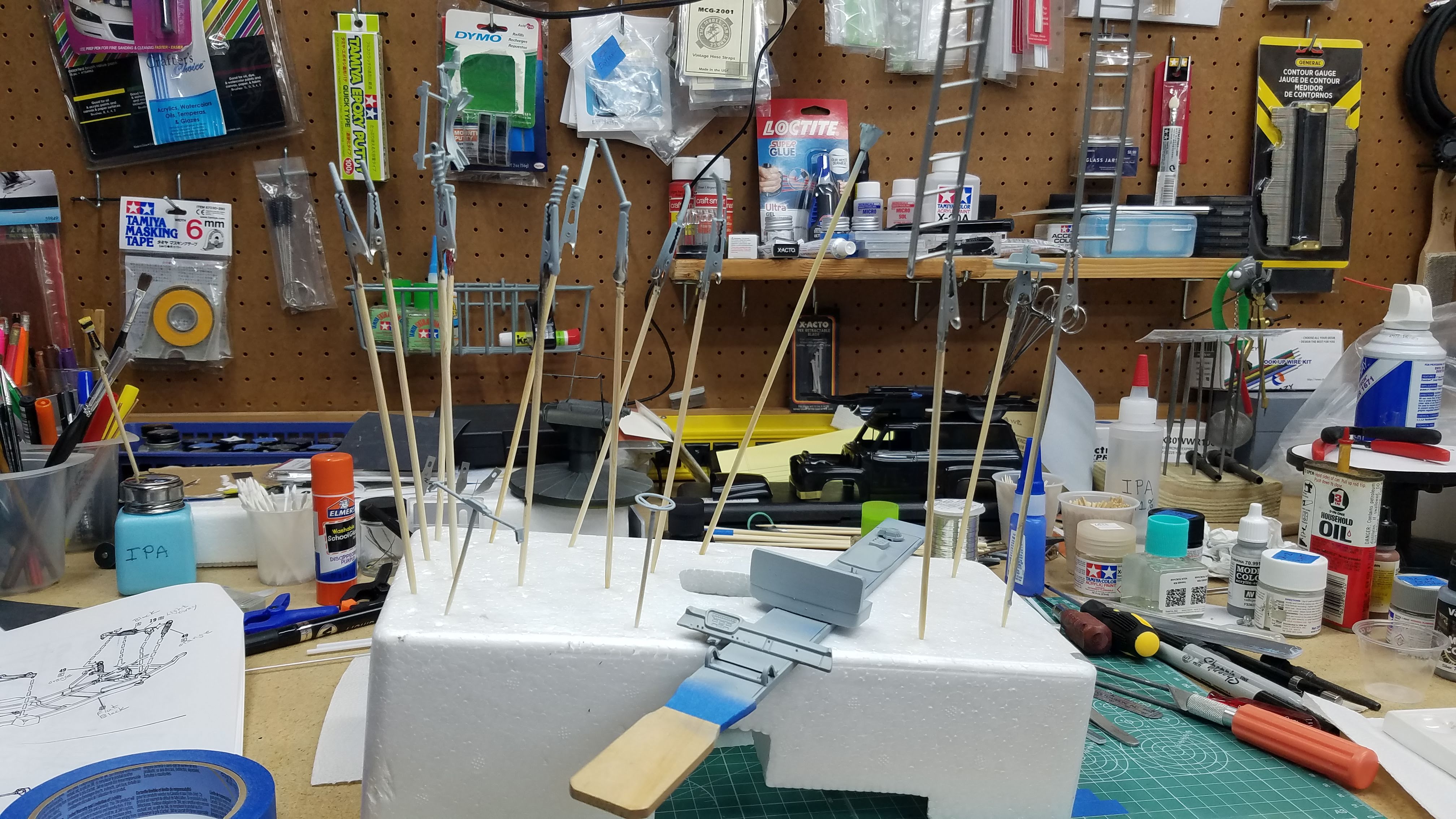
This is me in my messy shop. I used the orange extension cord to make a ring so that I can throw my hat in the ring and join this group build.
2 of 92
So...I've thrown my hat in the ring. I got that hat in Agrigento, Sicily. I've been to Sicily about 4-Times and the one time was during the summer. Sicily is H-O-T in the summer months. I bought the hat from a street vendor to keep the sun off me. I'm half Sicilian and I absolutely love Sicily. If you ever get a chance to visit the island, don't pass it up. It's a very beautiful place with great people and fantastic food.
3 of 92
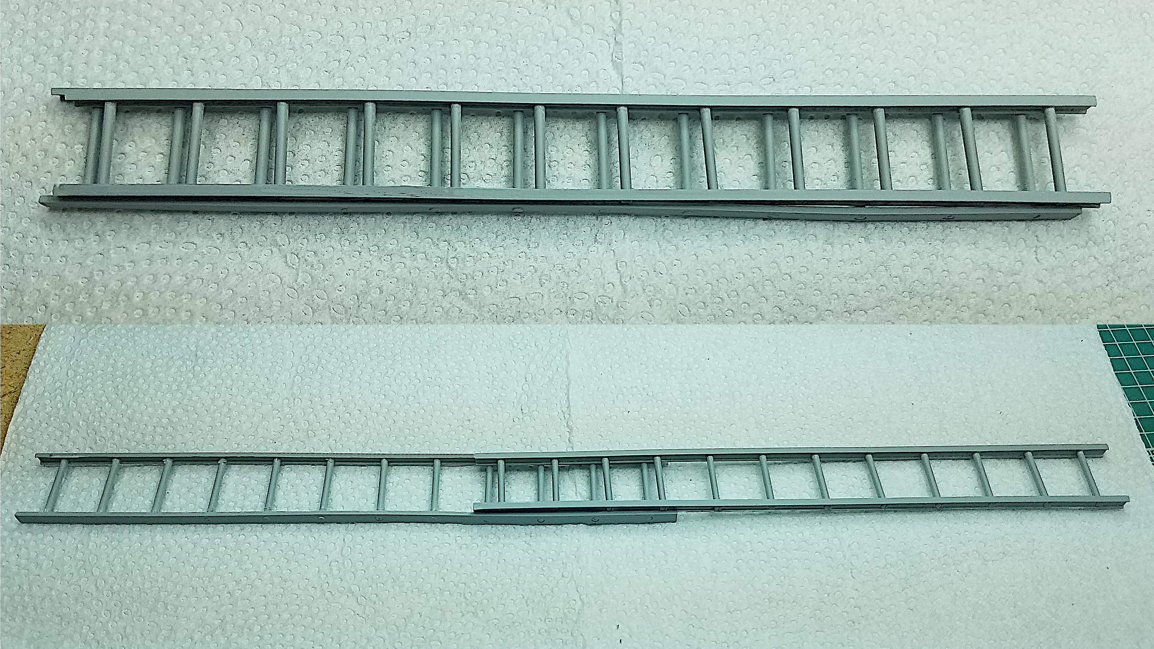
The first thing I did, after opening the box and sorting out the parts that I will be using, which isn't too many, was to scratch build a 1:24 scale working extension ladder. It is made from:
-
Evergreen #264 0.125"/3.175mm Channel
Sides of the outer ladder
0.125"/3.175mm is equivalent to 3"/76.2mm x 1"/25.4mm -
Evergreen #274 0.125" I-Beam
Sides of the inner ladder
0.125"/3.175mm is equivalent to 3"/76.2mm x 1"/25.4mm -
Evergreen #222 0.0625" Round Rod
Ladder rungs
0.0625"/1.5875mm is equivalent to 1.50"/38.10mm diameter
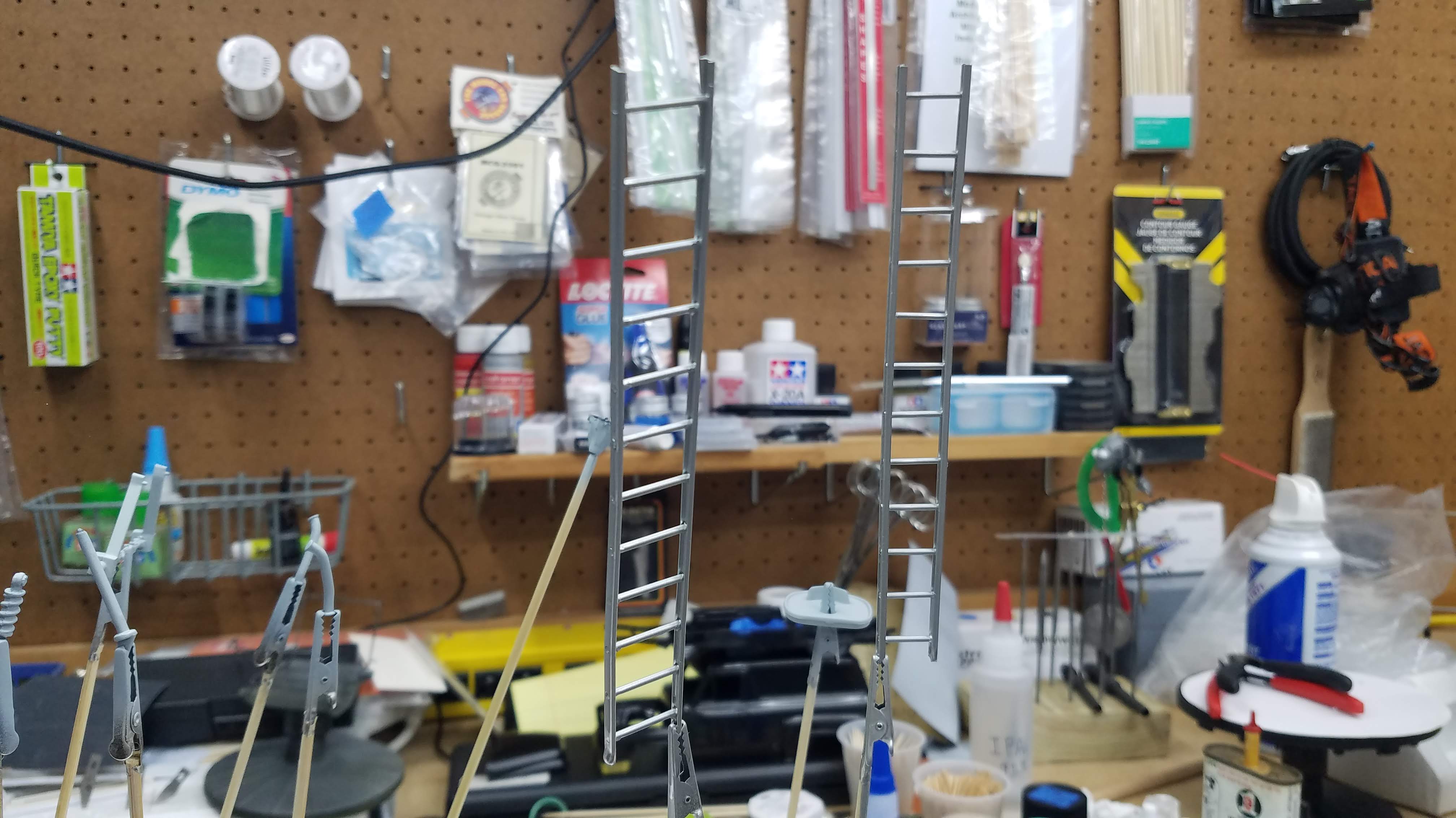
Each section is 6.0"/152.4mm long which is equivalent to 12'/3,657.6mm. When extended it would be the equivalent of a 24'/7,315.2mm ladder.
Upper photo is ladder ready for carrying and the bottom photo is the lader extended, almost full open.
4 of 92
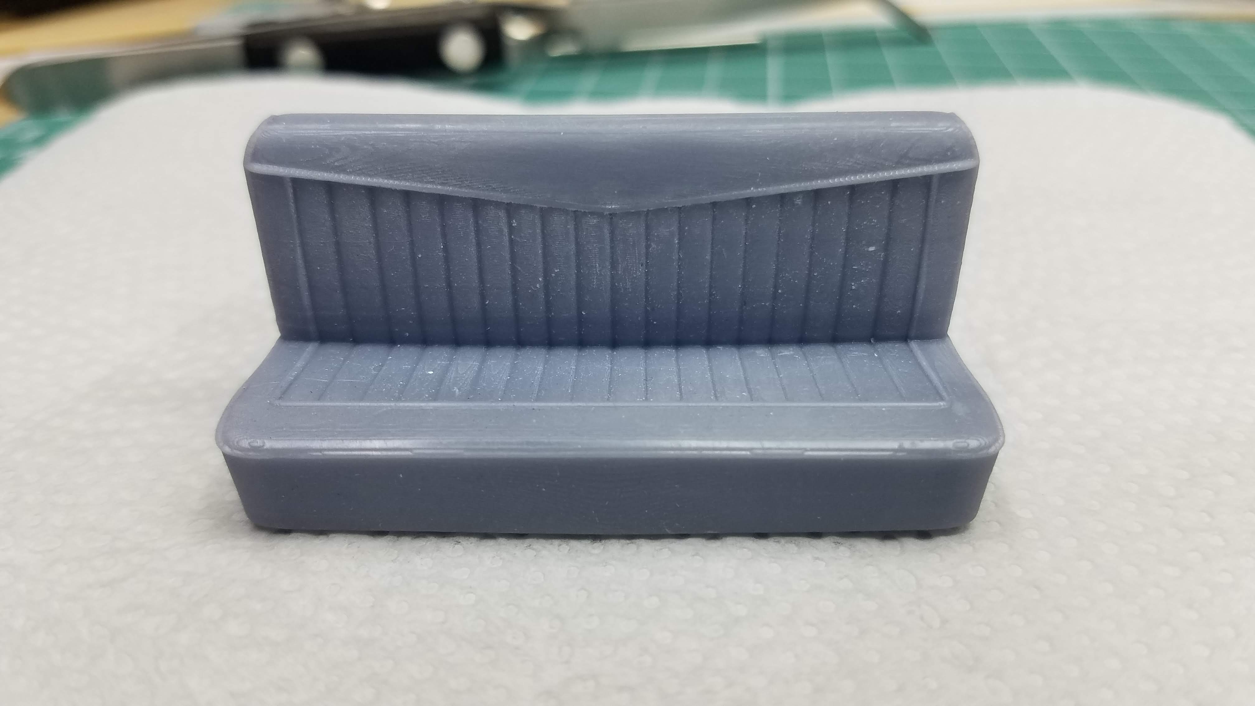
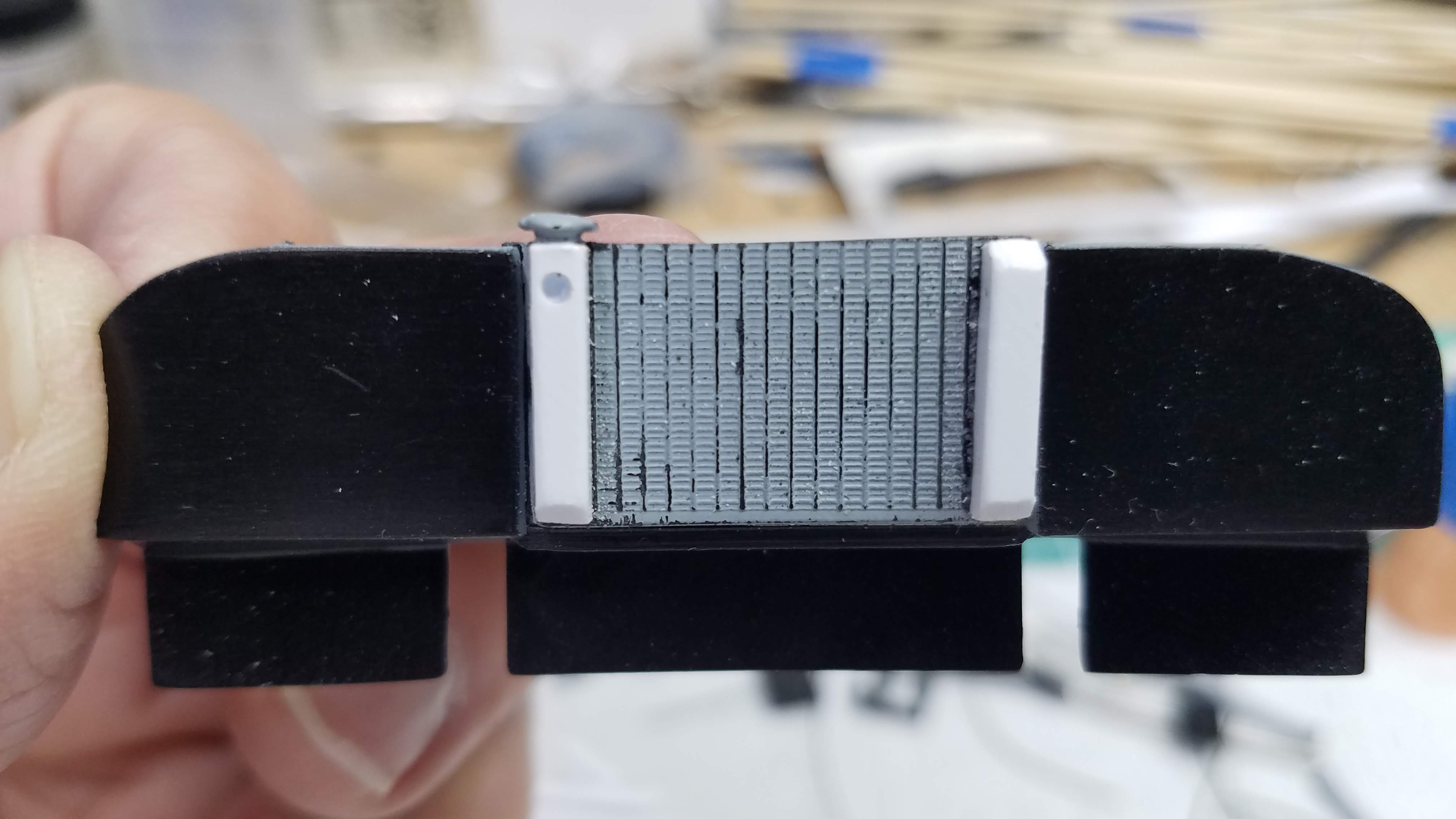
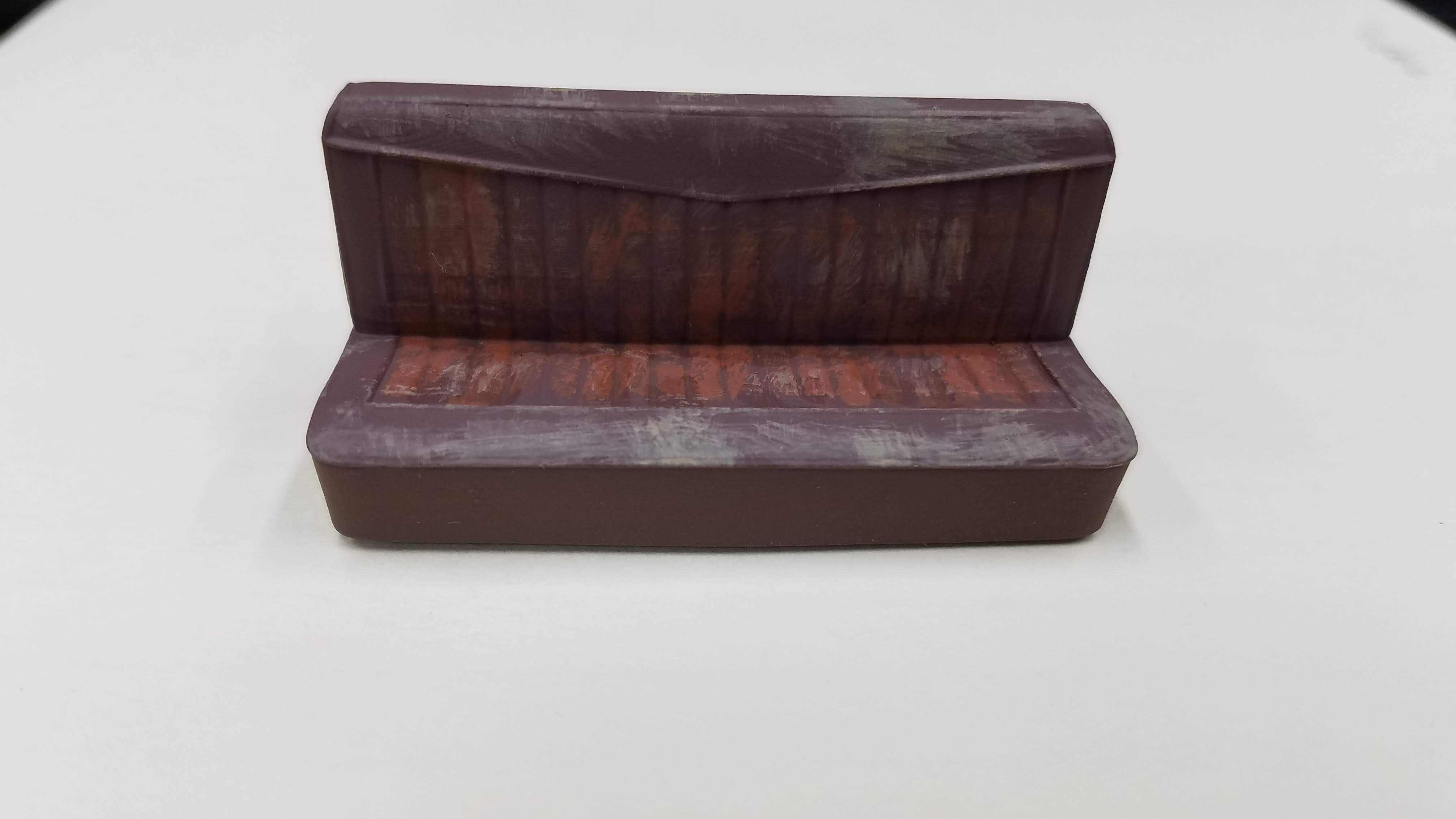
The kit comes with bucket seats. I don't like bucket seats in a truck, especially a panel truck; therefore, I found a 3D printed bench seat on Ebay. The seat had a Chevy logo in the center of the back leaner that I sanded off and it also came with a center console cup holder that I won't be using.
5 of 92
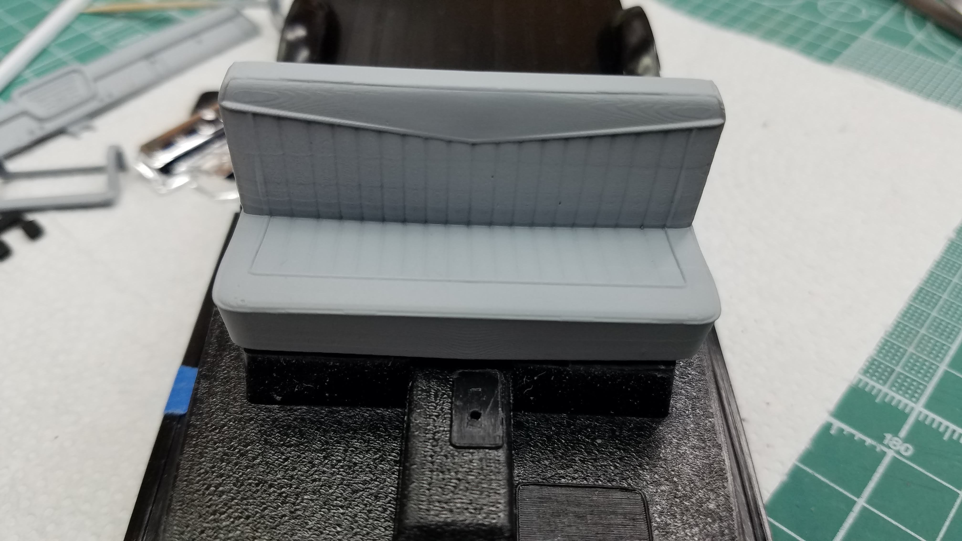
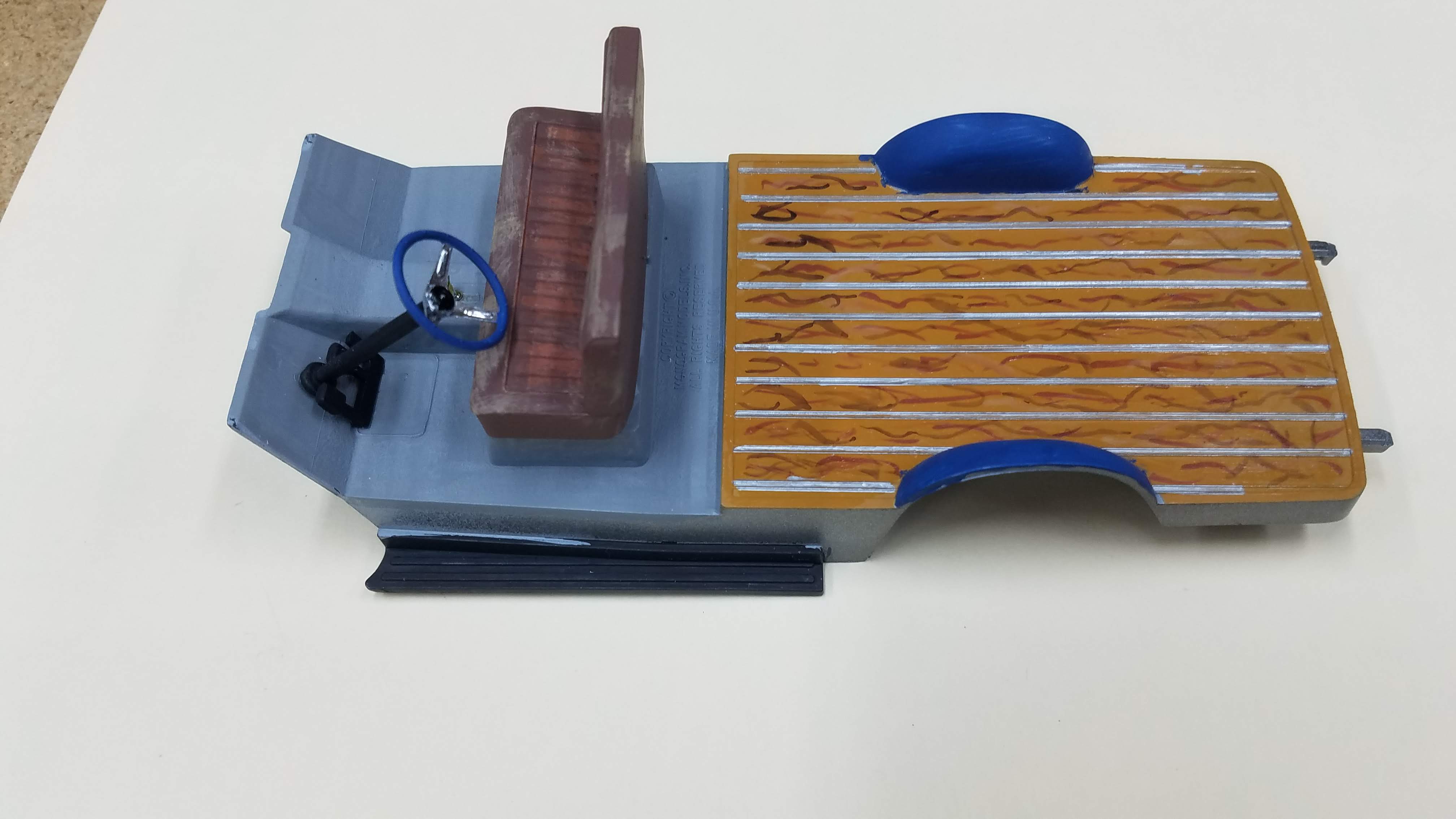
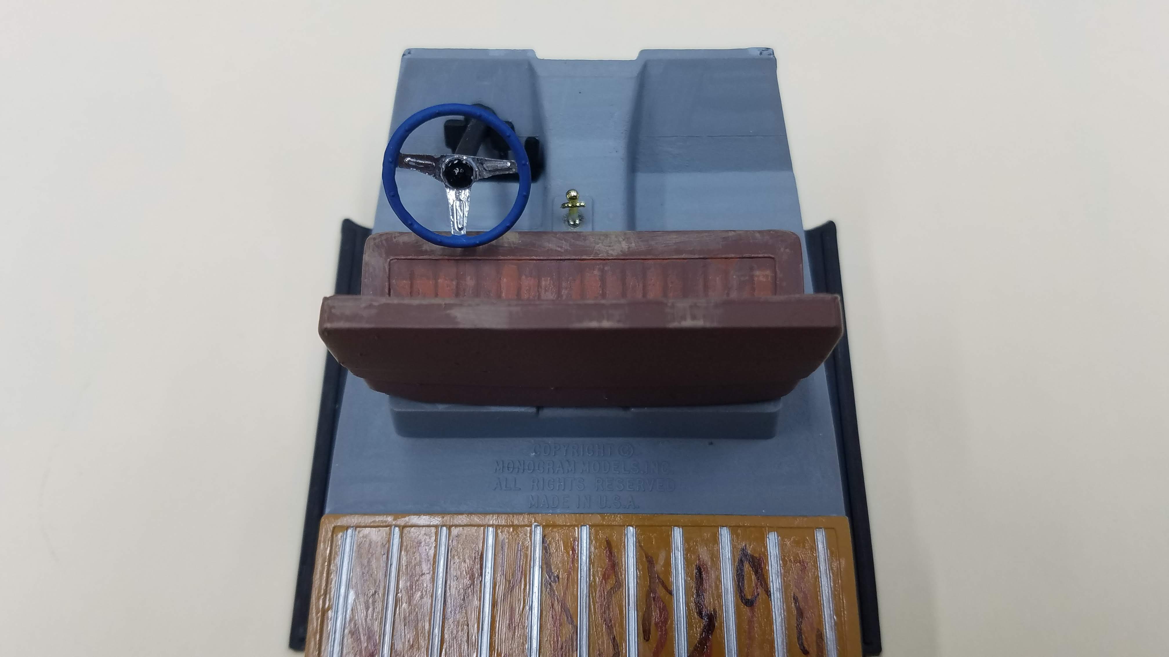
I dry fit tested the seat in the interior tub and it fits perfectly, but then I didn't have much doubt. It is a 1:24 scale seat.
6 of 92
After some light cleanup I started priming some of the smaller parts.
7 of 92
After some light cleanup I started priming some of the smaller parts. In this photo, the ladder received a coat of Vallejo Metal Color 77.701 Aluminum.
8 of 92
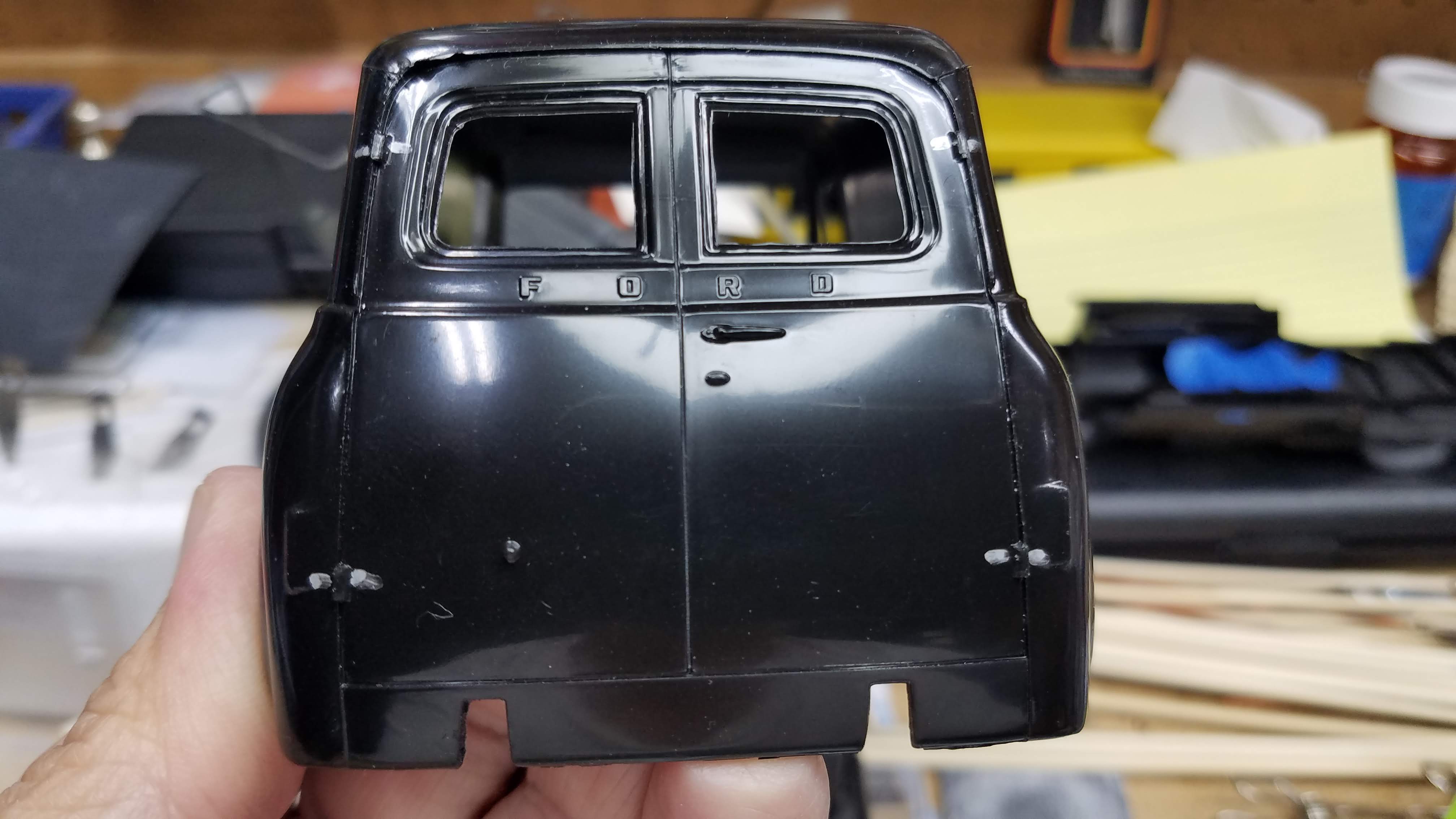
My original plan was to cut open the back doors. The hinges are very small and since I would be cutting and sanding, I used a silver sharpie to mark where the hinges are located.
In the end, I decided not to cut the door open for this build.
9 of 92
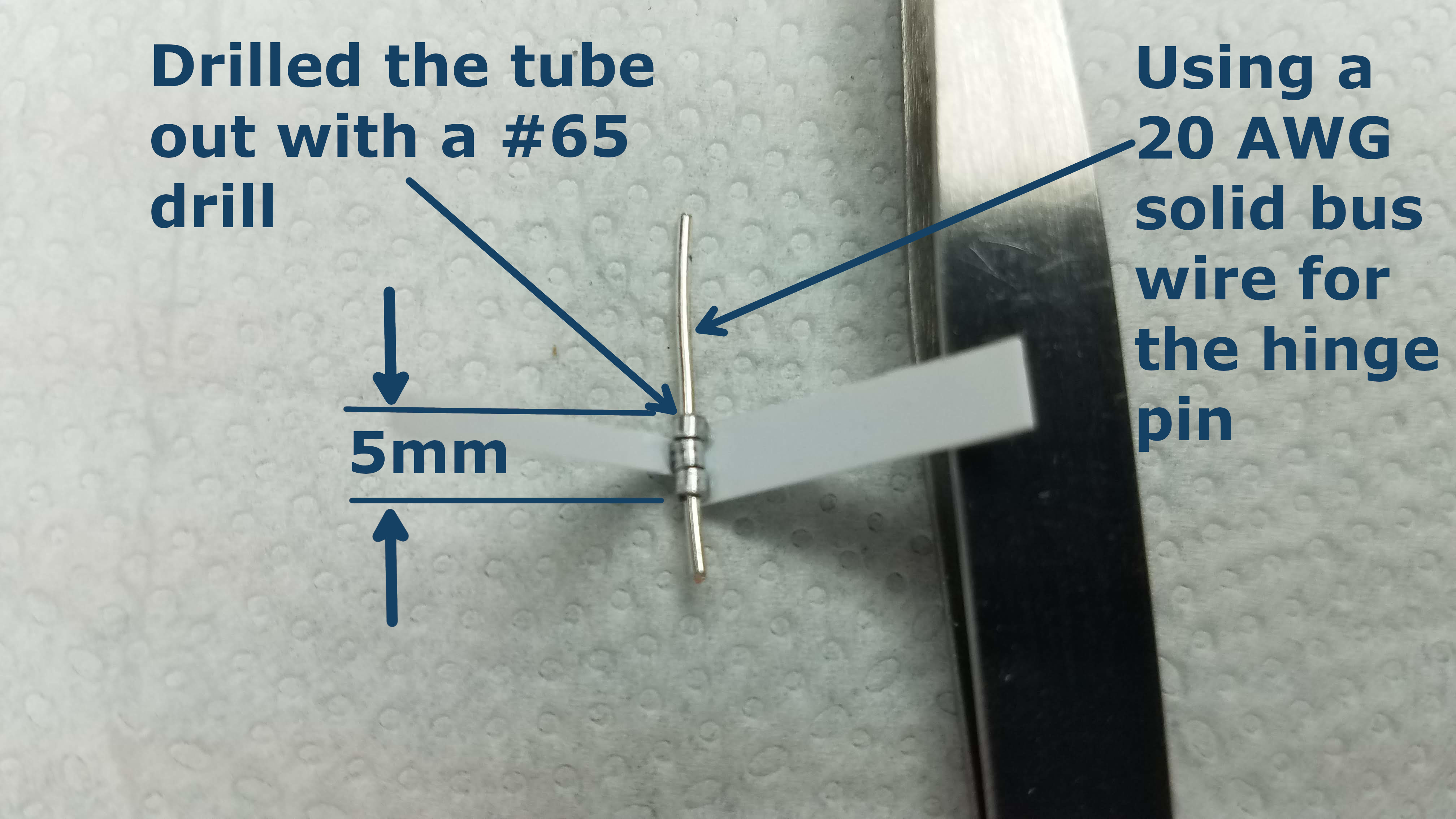
I had started researching how rear door hinges looked and functioned on an actual truck. I want to make it as realistic as possible. After many different ideas and failures, I think this design would work. The joint of the hinge is made from three pieces of 0.0625"/1.5875mm aluminum tube. Each section of the hinge is approximately 0.059"/1.5mm long. The tube was than drilled with a #65 (0.035"/0.889mm) drill to fit the hinge pin. The hinge pin is made with a 20 AWG (American Wire Gauge) solid bus wire. Two of the sections are glued to a piece of styrene with a gap equal to the length of one section (~1.5mm). Then, one section is glued to another piece of styrene. See my YouTube video 1055 Ford Panel Truck Part 02 to see how it is proposed to work. The hinge section starts at about 2:22 into the video and runs to about 5:42.
10 of 92
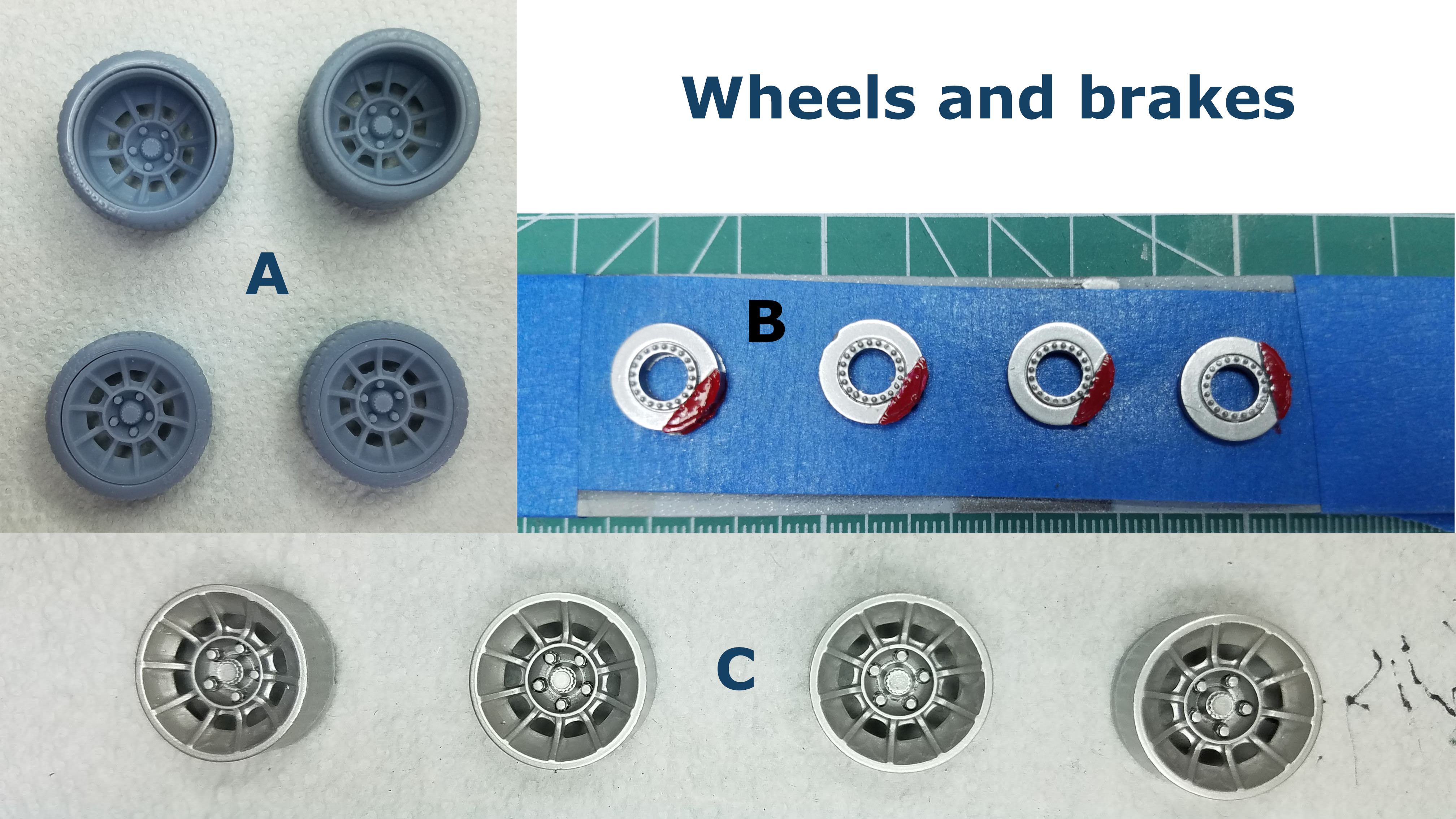
I'm not using the wheels and tires that came with the kit, although the 3D printed wheels and tires I'm using are very similar to the kit wheels. The wheels and tires in picture A were the first wheels I tried. It can be seen that the top two are wide with deep wheels. These did not fit well and gave a stance that I didn't like. The wheels in picture C are the ones I'll be using and have already been primed with Vallejo Metal Primer 77.660 Gloss Black and then two coats of Vallejo Metal Color 77.716 Semi Matt Aluminum. I'm going for a brushed aluminum look. Picture B are the brake rotors and calipers that came with the wheel/tires set.
11 of 92
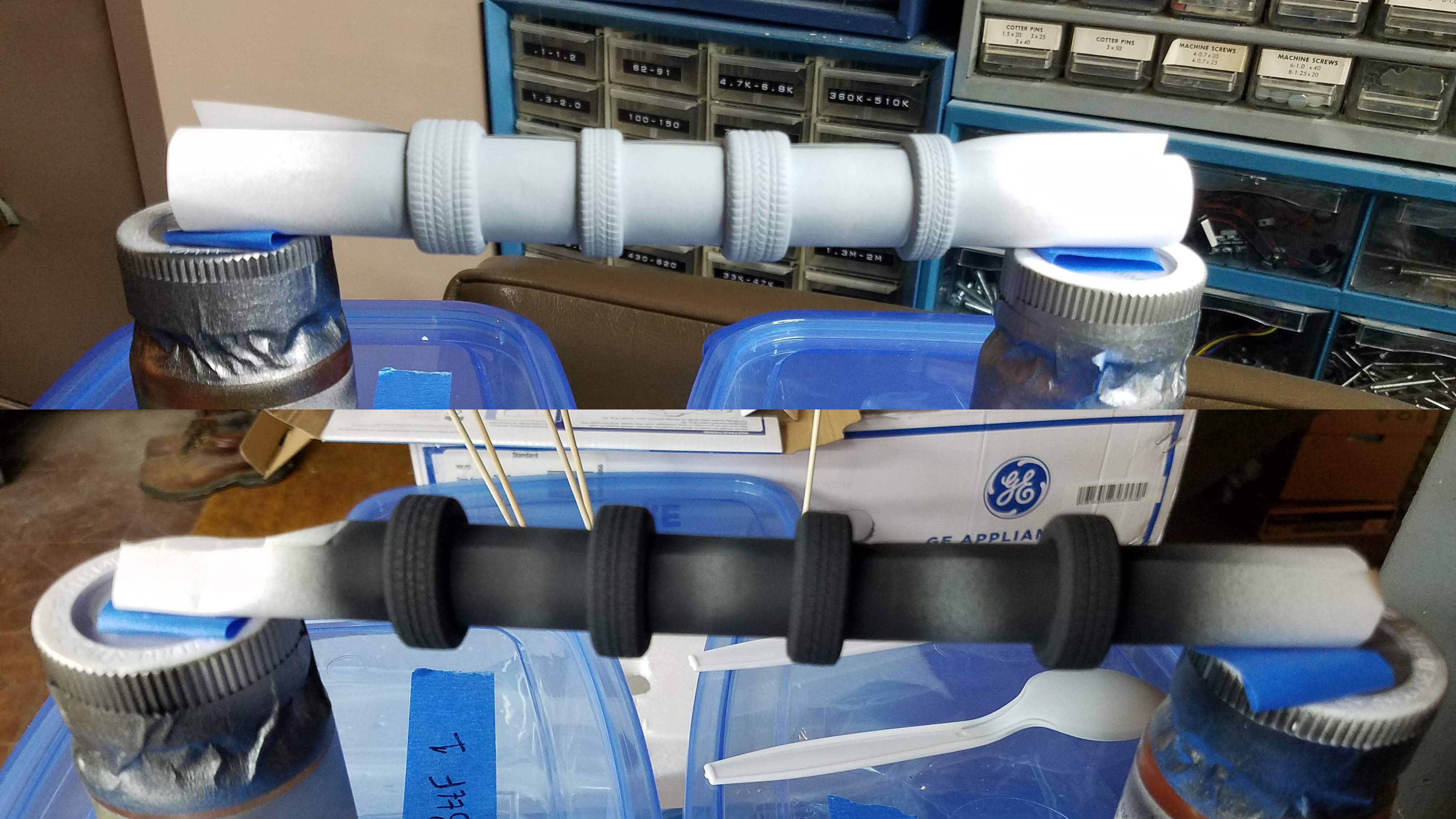
The top photo is the set of 3D printed tires that are not going to work for this build. They have been primed. The bottom photo is the set of 3D printed tires after a coat of Tamiya XF-85 Rubber Black was applied. I spray them by rolling up a sheet of paper and sliding the tires onto the roll. Then, the paper roll can be unrolled to fit snugly and hold the tires in place.
12 of 92
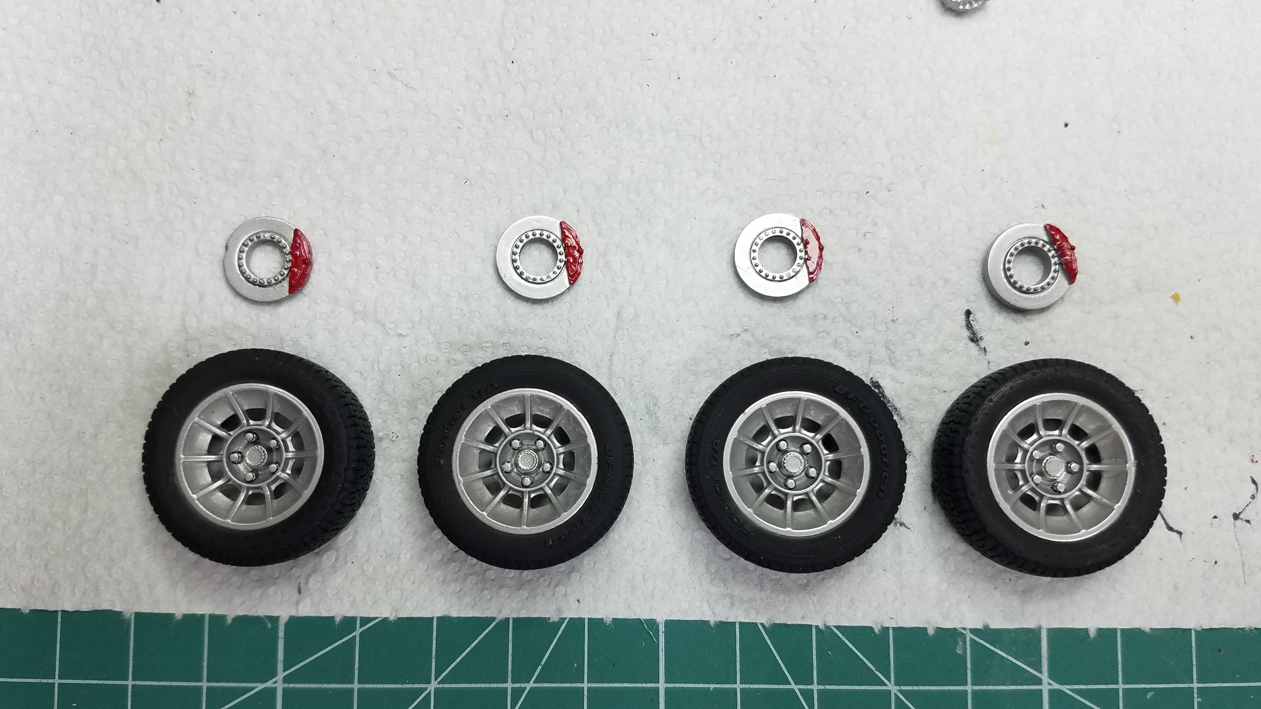
This photo is the 3D printed wheels and tires and the disc rotor with caliper. The wheels were sprayed with Vallejo Metal Color 77.716 Semi Matt Aluminum.
13 of 92
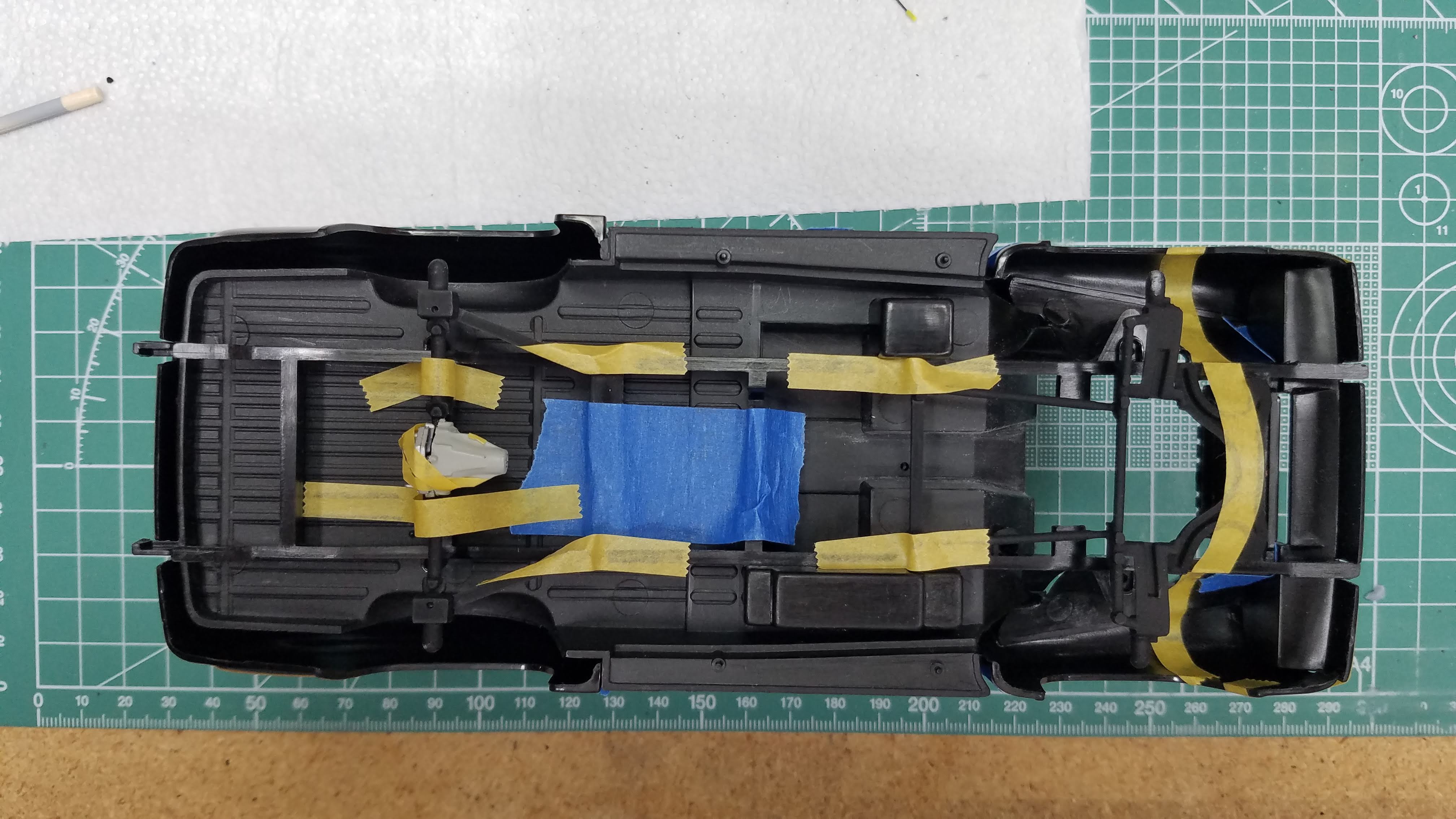
I taped the frame, front wheel axle and suspension, the rear differential and axle to check fit. The differential is painted with Tamiya XF-80 Royal Light Gray and the differential cover (not seen because it's covered with tape) with Vallejo Metal Color 77.716 Semi Matt Aluminum.
14 of 92
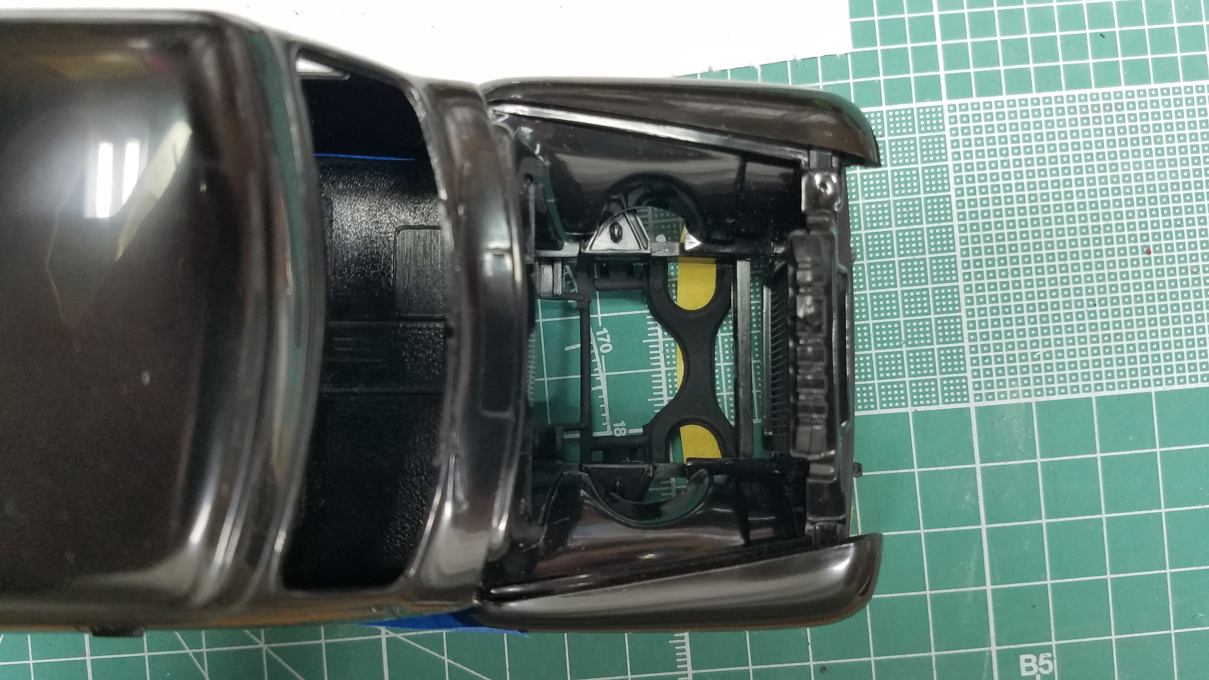
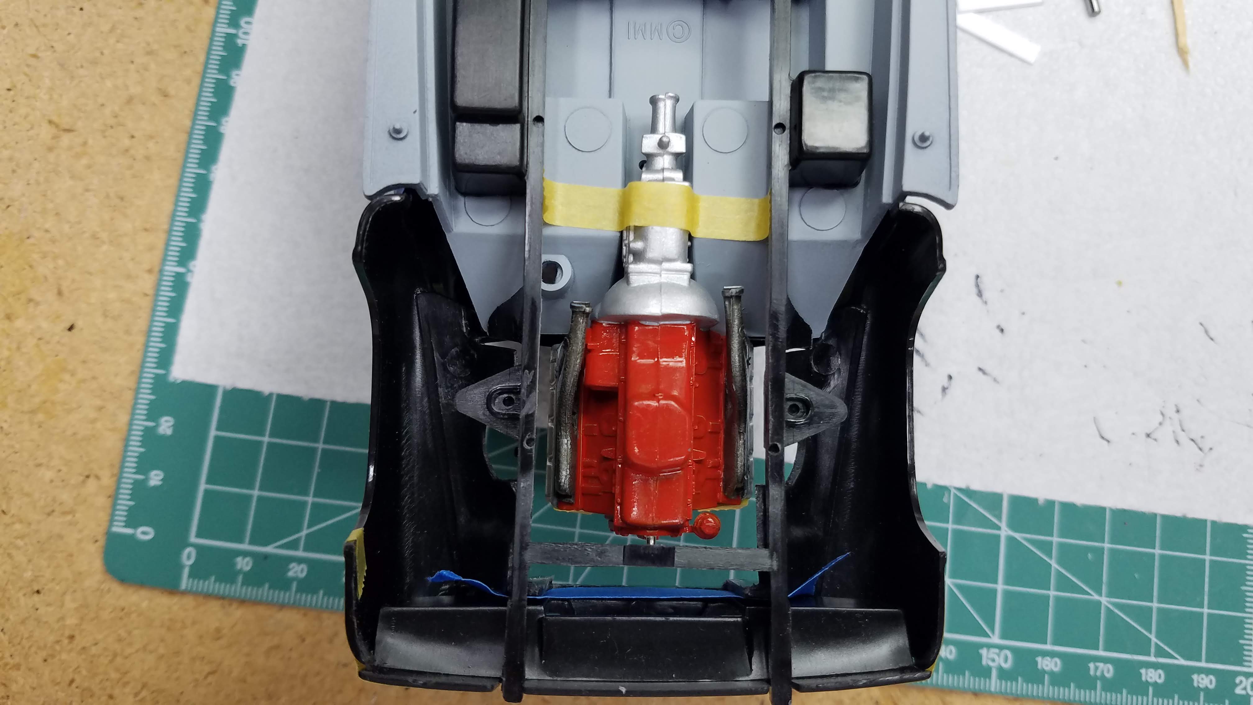
With body and frame parts dry fitted and the radiator installed, I was checking if there is room to mount the '71 426 Hemi Elephant engine. When this photo was taken I thought it would fit just fine; however, after adding an after market pully/belt set to the engine, it will not fit with the kit radiator in place. There will be more on this later.
15 of 92
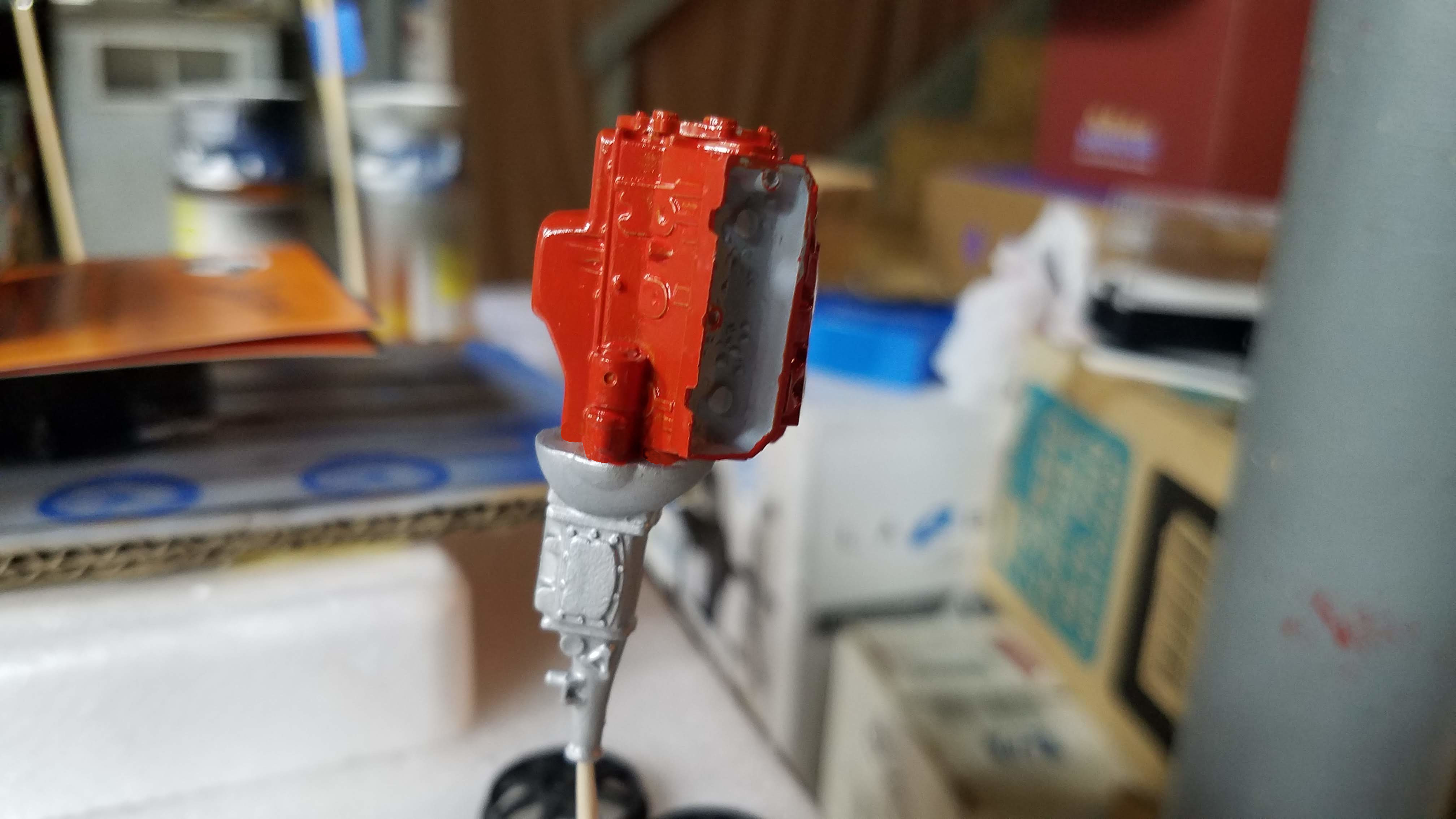
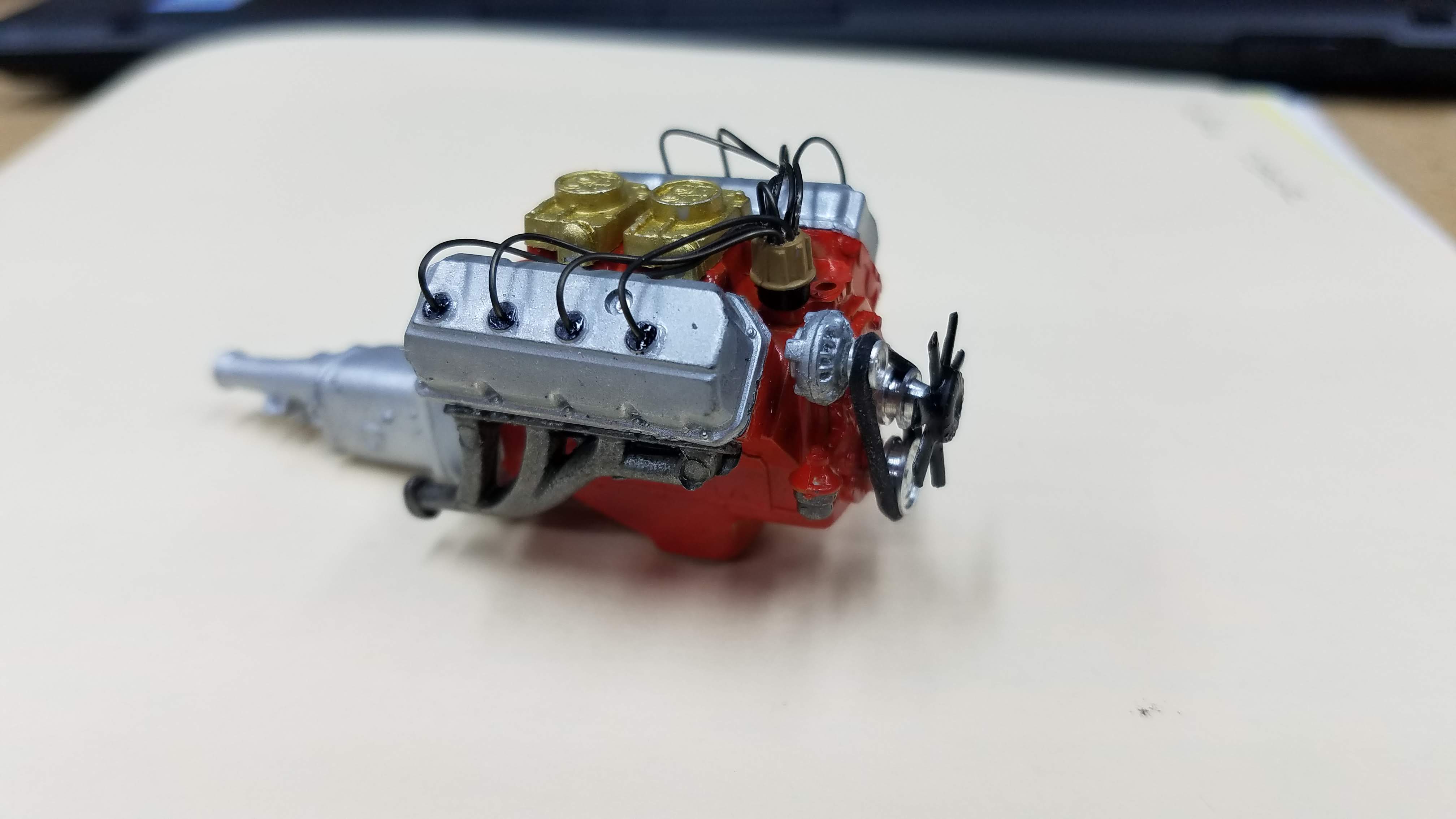
I started building the engine. As I said before, the engine is a 1971 Plymouth Cuda 426 Hemi. It was sometimes referred to as "The Elephant Engine". Because it is a Plymouth, a Chrysler product, I wanted to paint the engine block, head, oil pan and water pump Chrysler Engine Red. Testers used to make the color; Chrysler Engine Red (Model Master #TES2732); however, most of you know that Model Master paint is no longer produced. I found a bottle on Ebay, but I was afraid it might have been dried out, so I passed on it. I mixed my own Chrysler Engine Red based on how I remembered my '66 Plymouth Valiant 200, 225 Slant Six engine looked. The color isn't really red, it's more orange/red. To achieve the color I mixed 20-drops of Tamiya X-6 Orange with 8-drops of Tamiya X-7 Red (2.5:1.0, Orange:Red). I think this gave me a fairly good match to what I remember the engine color looking like. The transmission and bell housing were painted with Tamiya XF-16 Flat Aluminum.
16 of 92
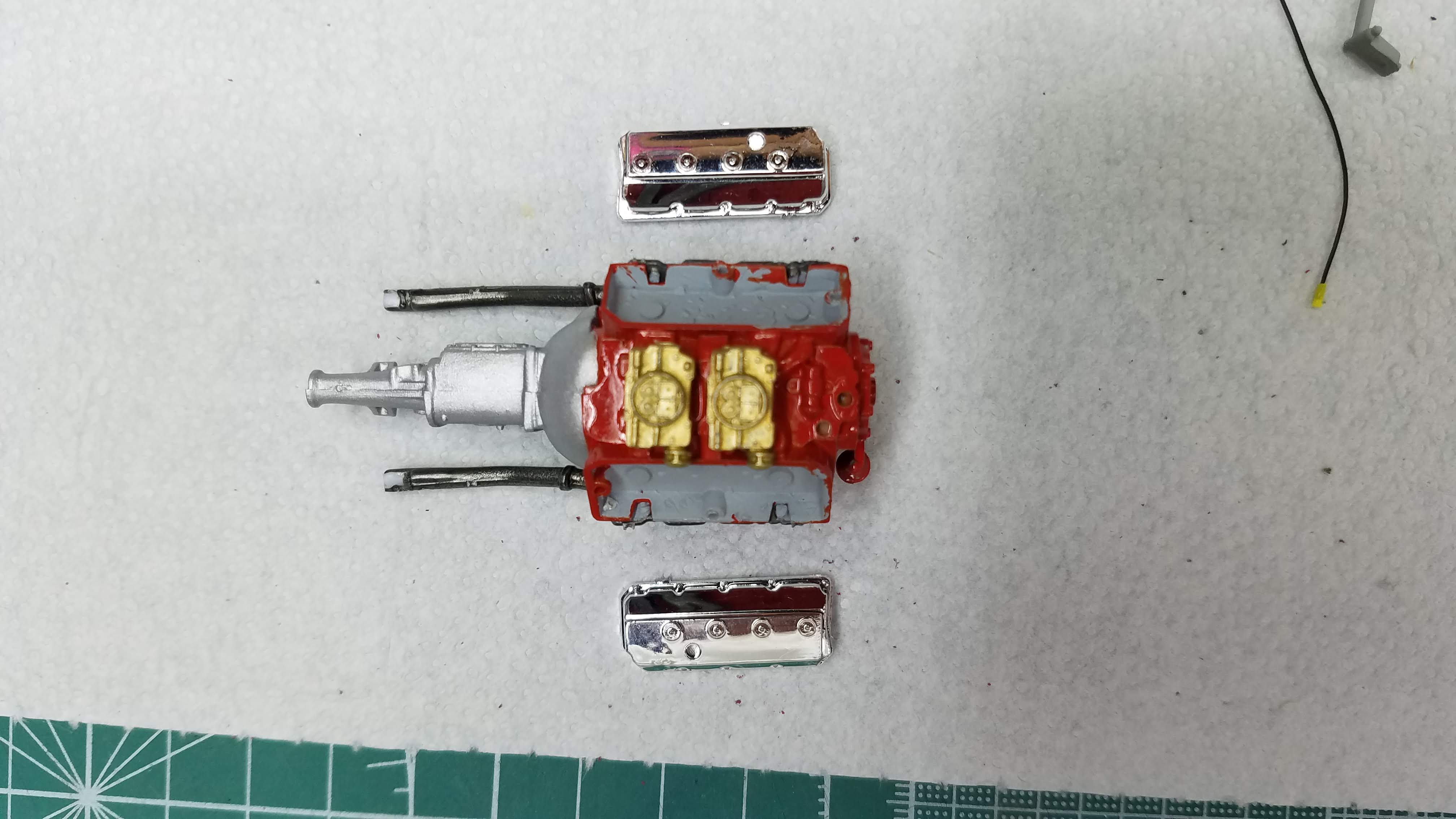
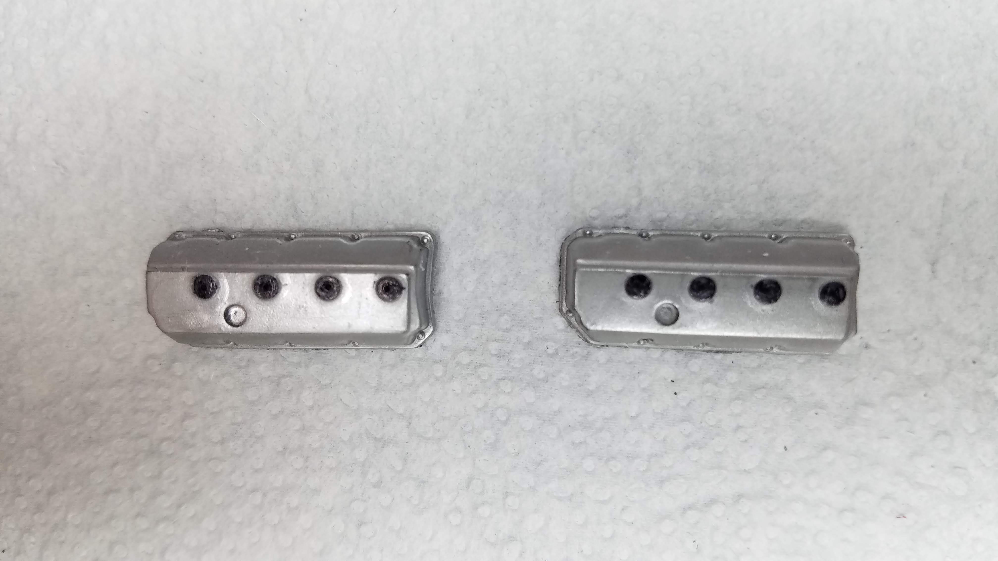
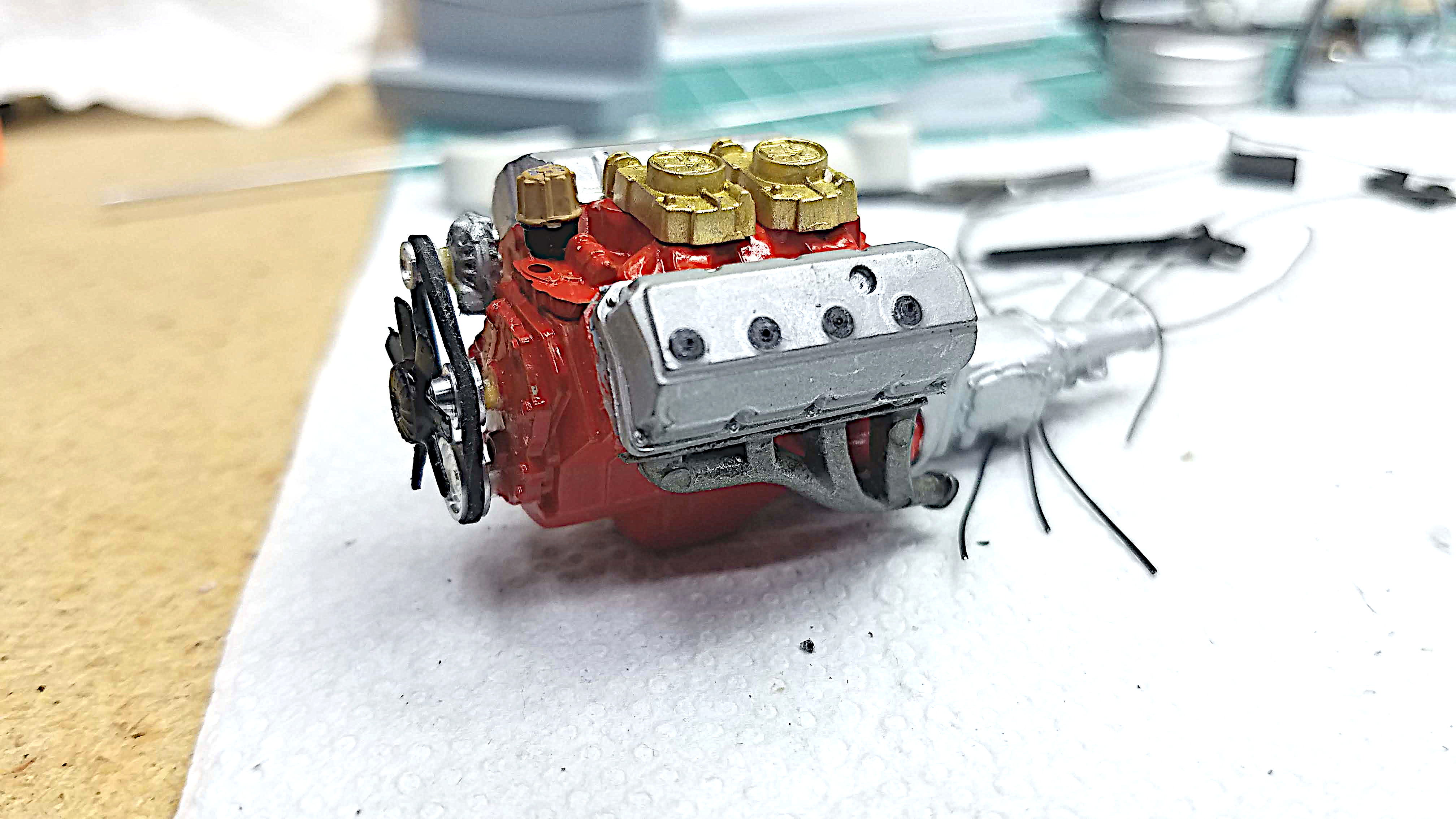
I added the two carburetors and painted them Tamiya X-12 Gold Leaf. The exhaust manifolds were also added and painted using Vallejo 77.723 Metal Color, Exhaust Manifold. I ended up having to cut off the pipes shown in this picture to fit the engine in the trucks engine compartment. As shown, the valve covers are chrome. I don't like chrome valve covers and later stripped the chrome from them.
17 of 92
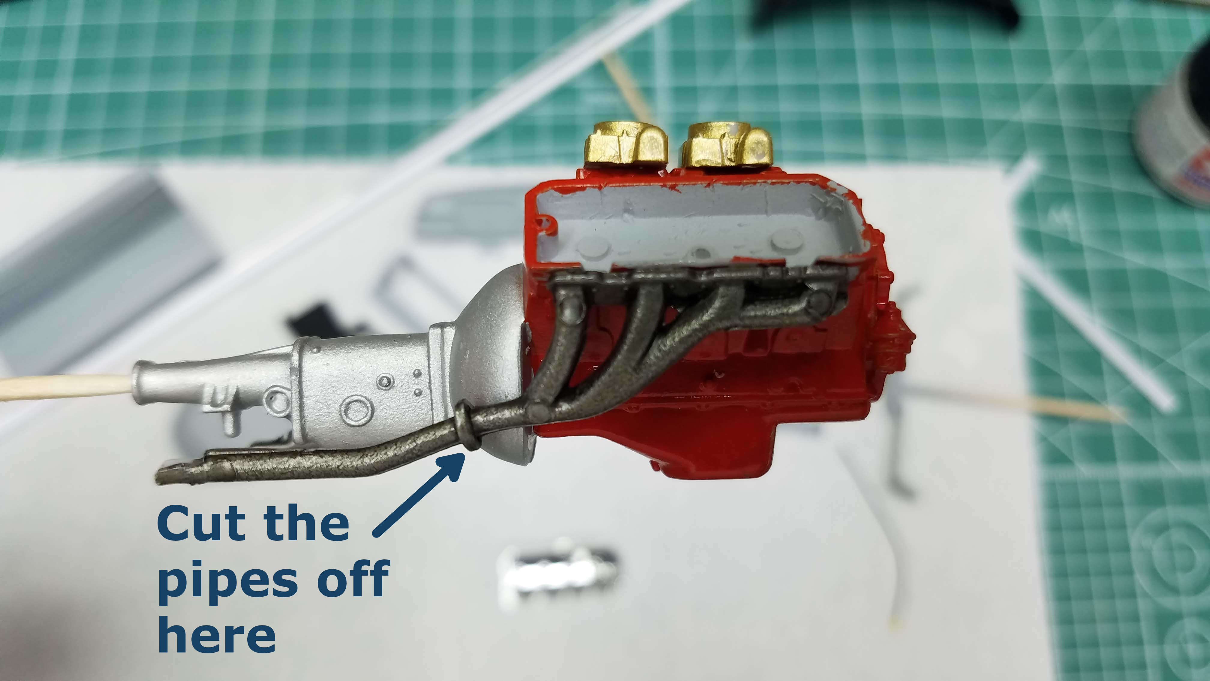
This is just a side view of the engine to show where I cut the exhaust pipes to make the engine fit.
18 of 92
After the chrome was stripped from the valve covers I painted them using Vallejo Metal Color 77.716 Semi Matt Aluminum. I wanted to get a brushed aluminum look and this was the closest I was able to get to that look. I then used a black Sharpie to color the spark plug covers.
19 of 92
I test fitted the engine several time, taping it in location. This photo also shows the exhaust pipes had been cut off. At this time I still have not figured out how I was going to mount the engine to the frame.
20 of 92
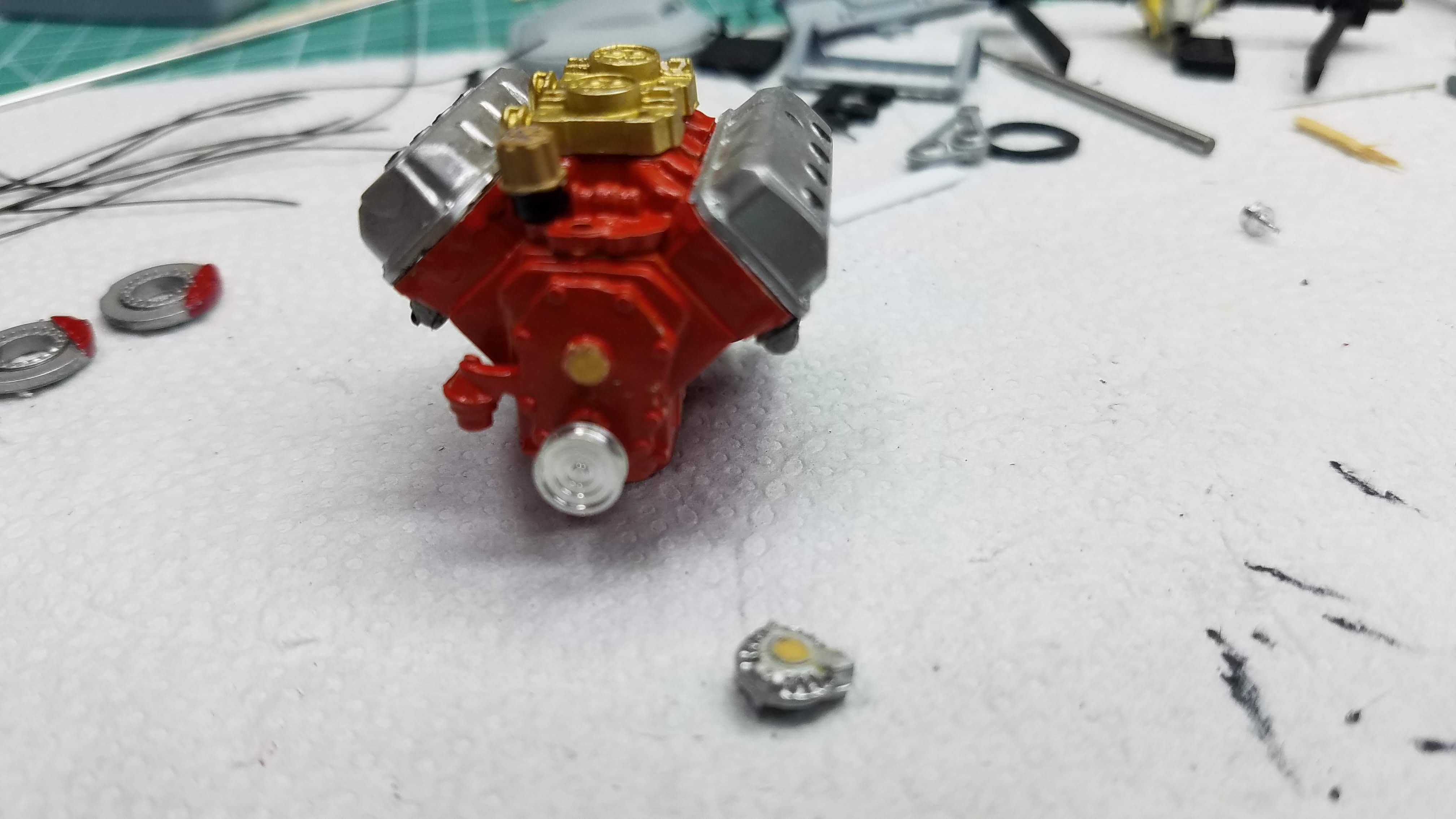
The valve covers were installed, the distributer was painted and drilled for wiring. The distributer cap is painted with Tamiya XF-59 Desert Yellow and the base is Tamiya X-18 Semi Gloss Black. I also started installing the 3rd party pulley and belt set from Motel Car Garage #MGC-201 Signal Drive Set for Stock Vehicles.
I used the existing hole for the crank pulley; however the
water pump pulley would have to be moved a bit higher and
the hole in the alternator was too large. Here is where I
made a very stupid mistake/oversight. I used Tamiya RCECHO174
Epoxy Putty Quick Type to seal the holes so that I could
redrill them. After two days the putty was still not hard.
So...I stuck the pulleys into the putty and applied some
Loctite to hold them in place. Another two days went by
and the pulleys were still not secure. I found this out
while shooting the update video
04 1955 Ford Panel Truck USACC Part 04.
It was during the shooting of this video that I realized
the putty is a two part epoxy and I hadn't mixed the two
parts together...DUH!!! I was and am so very embarrassed.

21 of 92
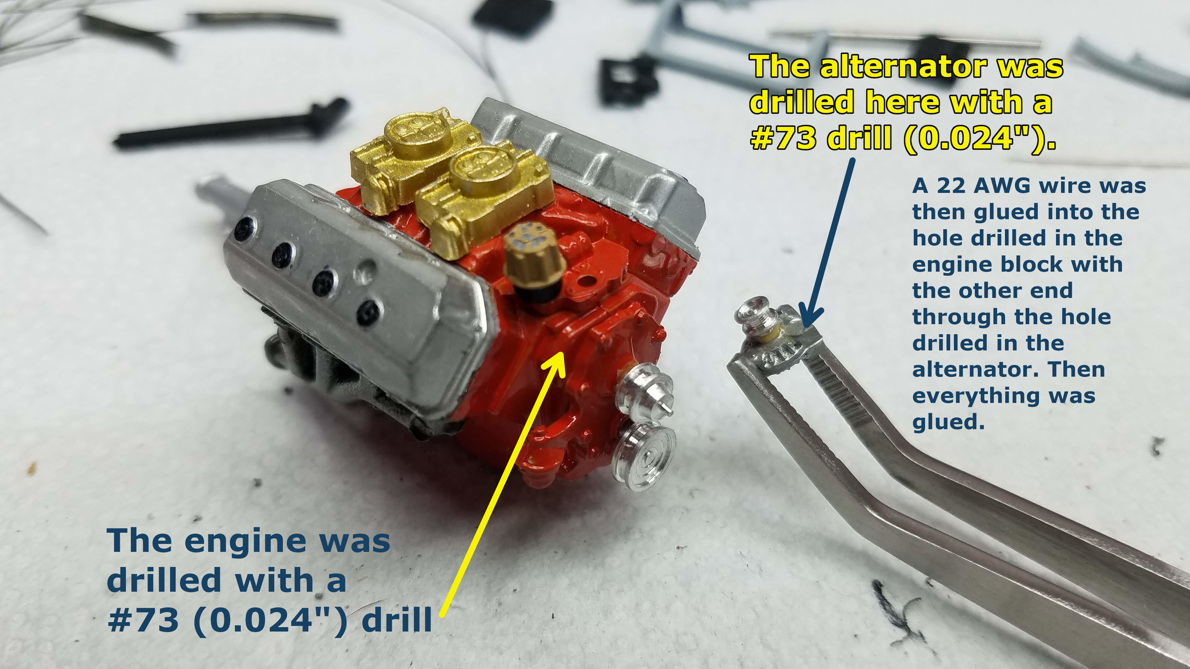
The engine pulleys are in place and the alternator pulley is installed. The alternator housing will be drilled and the engine block will be drilled to pin the alternator to the engine block.
The alternator and the engine block were drilled with a #73 (0.024"/0.6096mm) drill in the locations shown. Then a pin was made with a short length of 22 AWG (American Wire Gauge) solid bus wire. One end of the wire was first glued into the hole drilled in the alternator. When the glue dried, the other end of the wire was inserted into the hole drilled into the engine block and glued in place, mounting the alternator to the engine block. Using a pin made the attachment of the alternator much more ridged and much less likely to break off.
22 of 92
The pulleys, alternator and belt are installed.
23 of 92
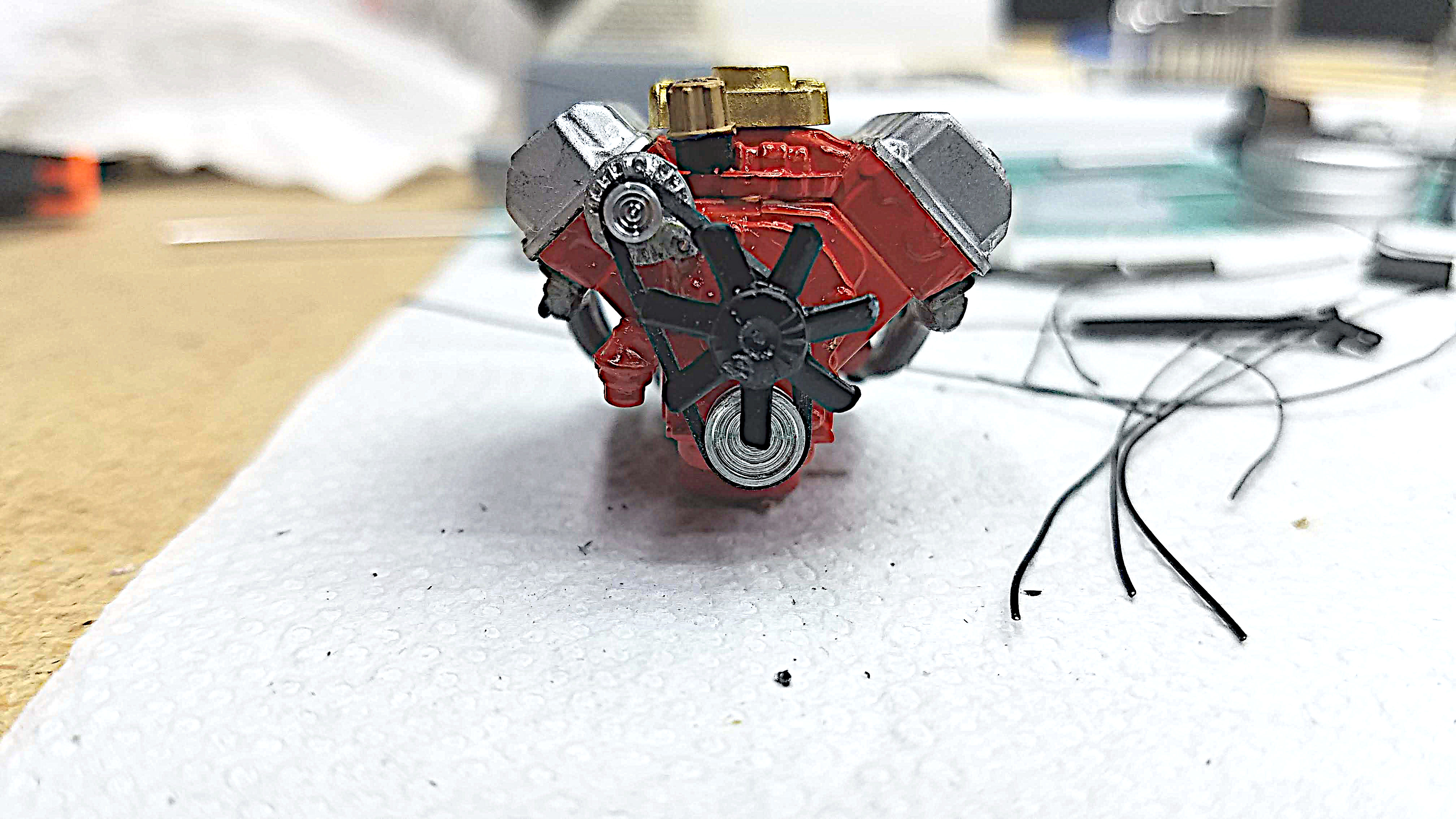
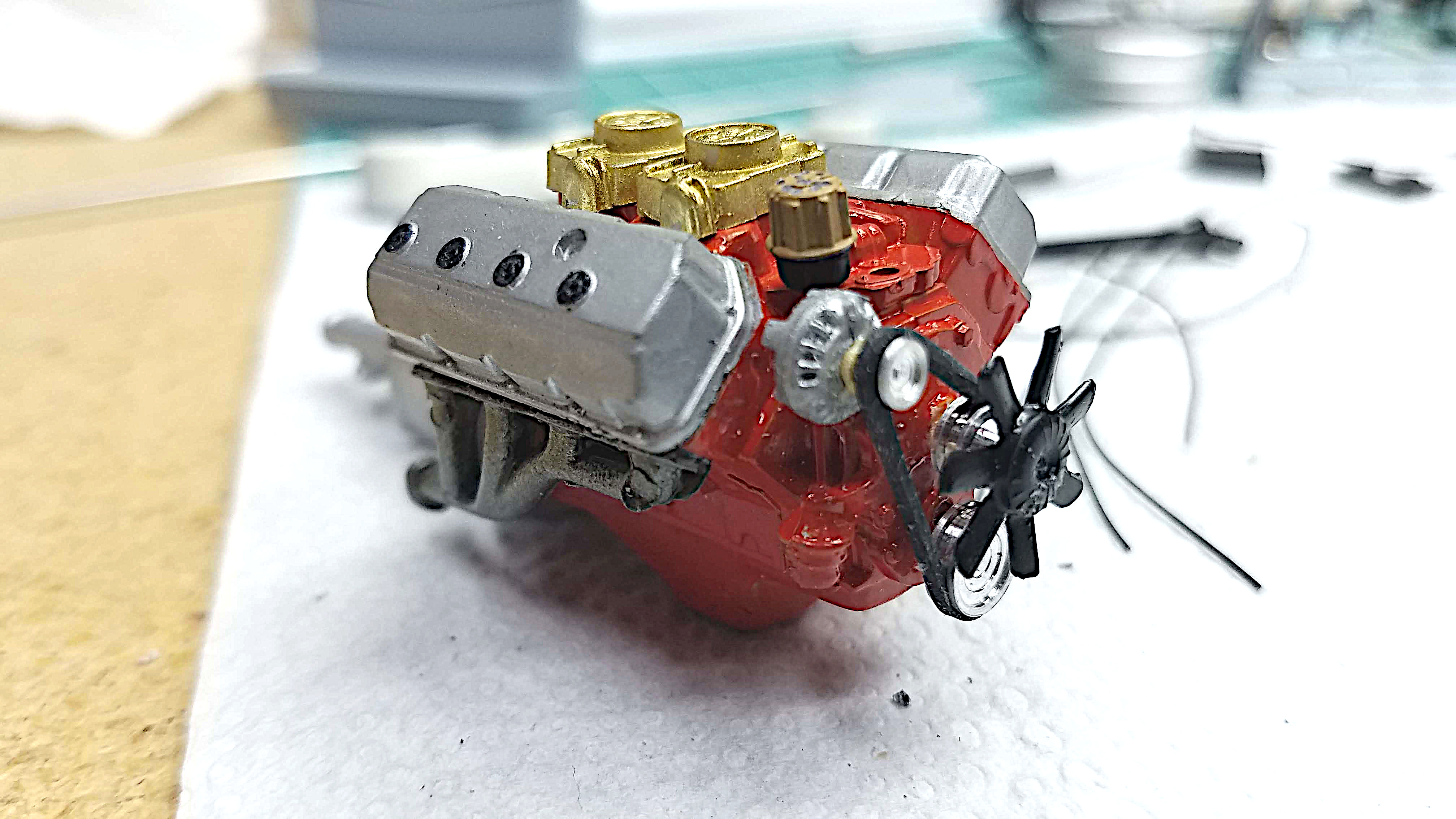
This photo and the next are different angles of the engine.
24 of 92
This photo and the previous one are different angles of the engine.
25 of 92
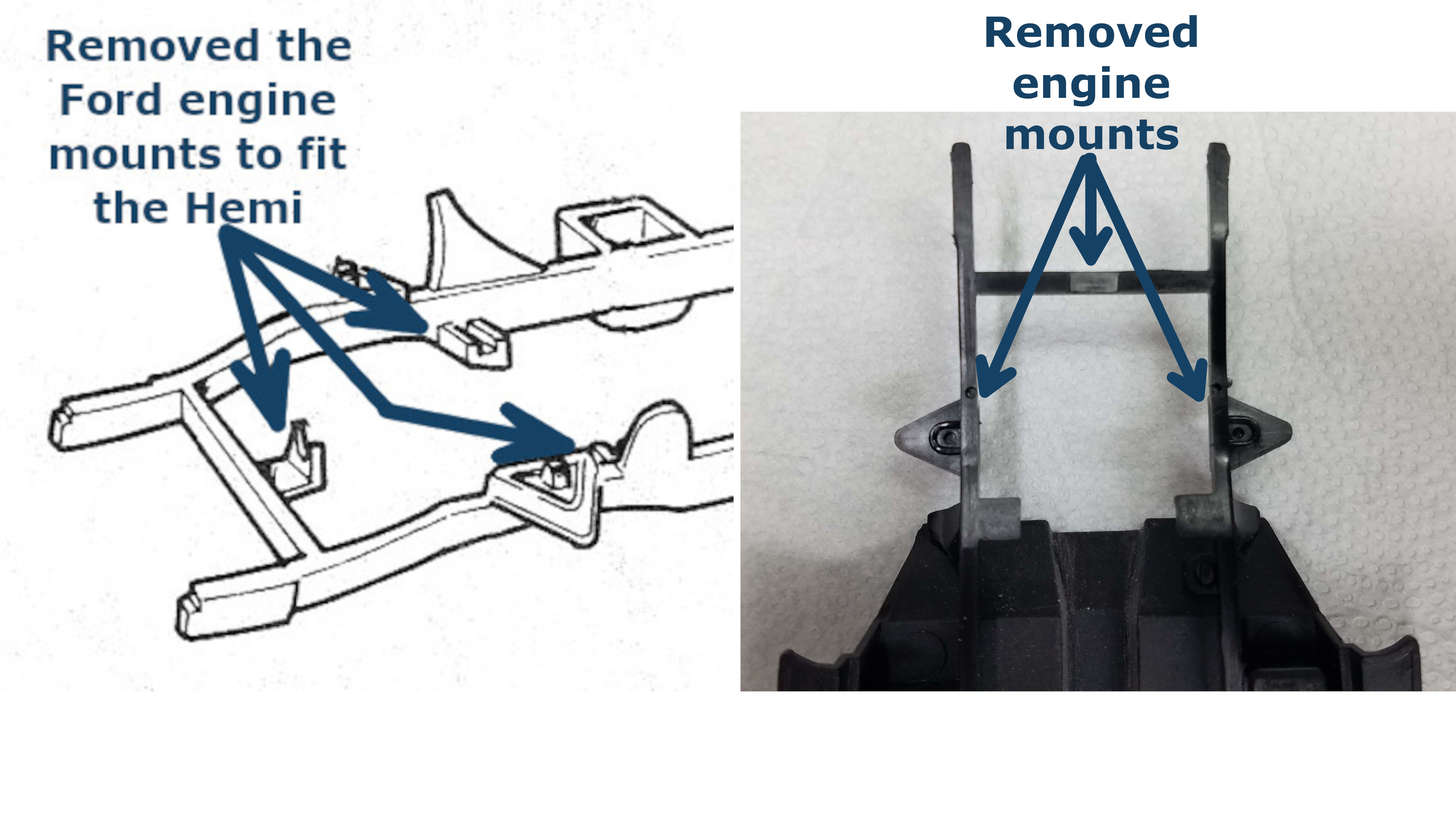
To make the 426 Hemi fit, the motor mounts for the original Ford engine had to be removed from the frame. This picture is a clip from the instruction sheet showing what mounts were cut and the inset photo is the chassis with the mounts removed.
26 of 92
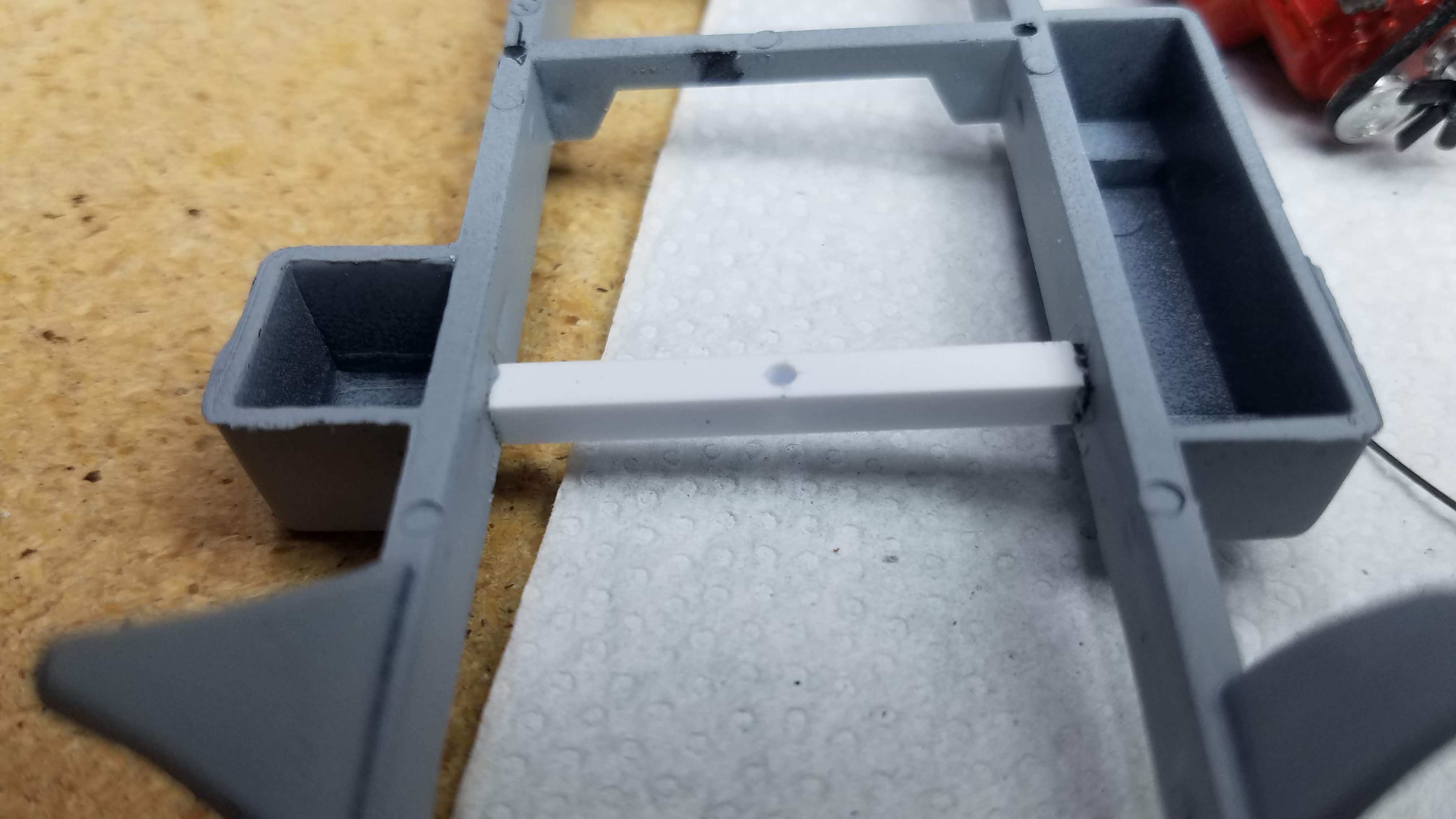
My first attempt at making engine mounts was to add a cross member near the front of the frame. The cross member was made using a piece of 0.10"/2.54mm square stock. I really didn't like this because it meant the front end of the engine would be setting on the oil pan...not realistic.

27 of 92
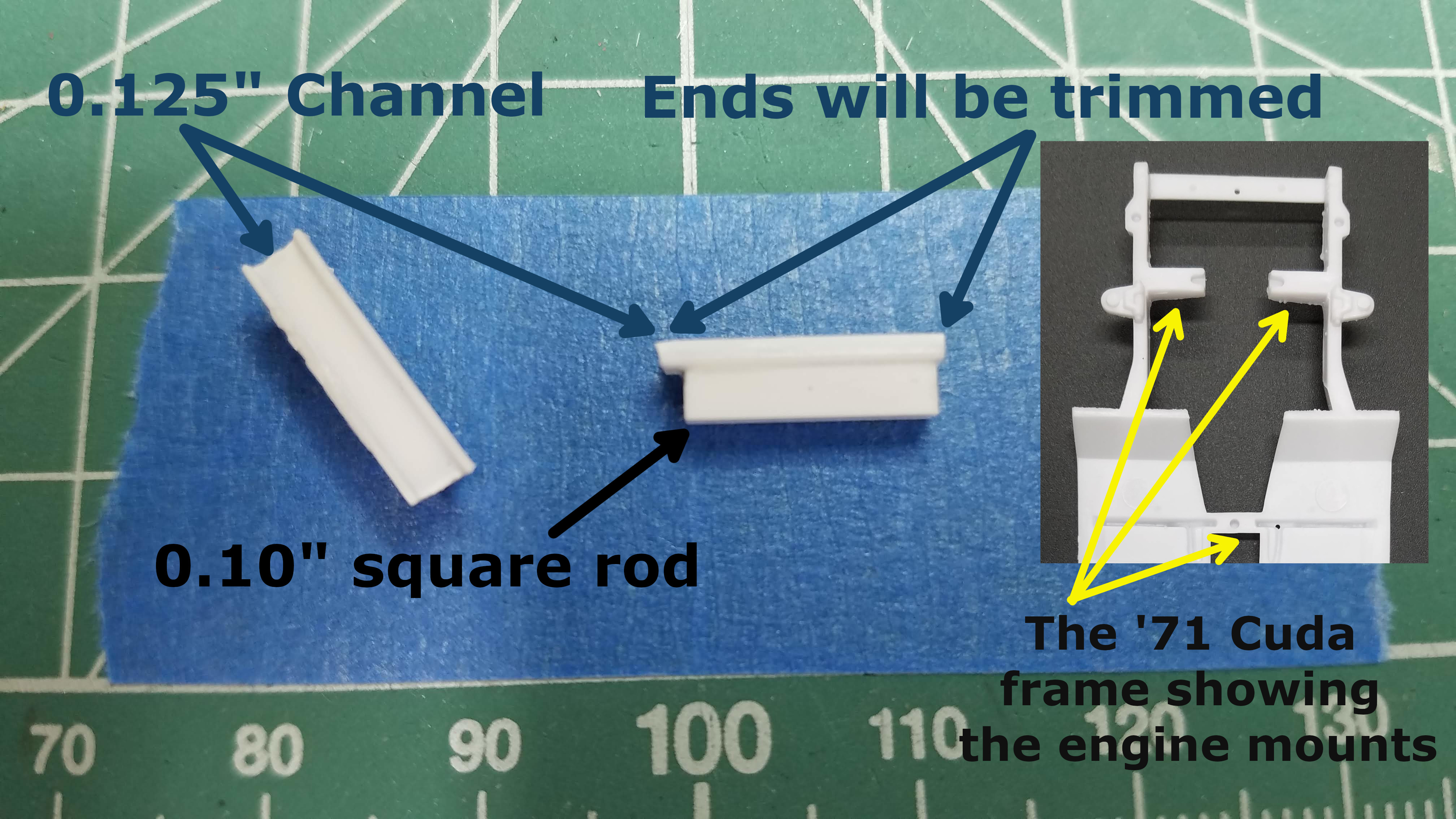
After pondering this problem for a few days and watching some other YouTube video's of other USACC builders having similar problems mounting their engines, and examining the frame from the '71 Cuda, I came up with a simple solution using 0.100"/2.54mm square rod and 0.125"/3.175mm Channel. These pieces will be trimmed and then installed on the frame in a location that will use the Hemi engine mount points.
The inset photo shows the '71 Cuda frame with its engine mounts. The mounts I fabricated are very similar to the Cuda mounts.
28 of 92
The scratch built engine mounts were added to the truck frame, and the cross member that was previously installed, that the oil pan was setting on, was removed.
29 of 92
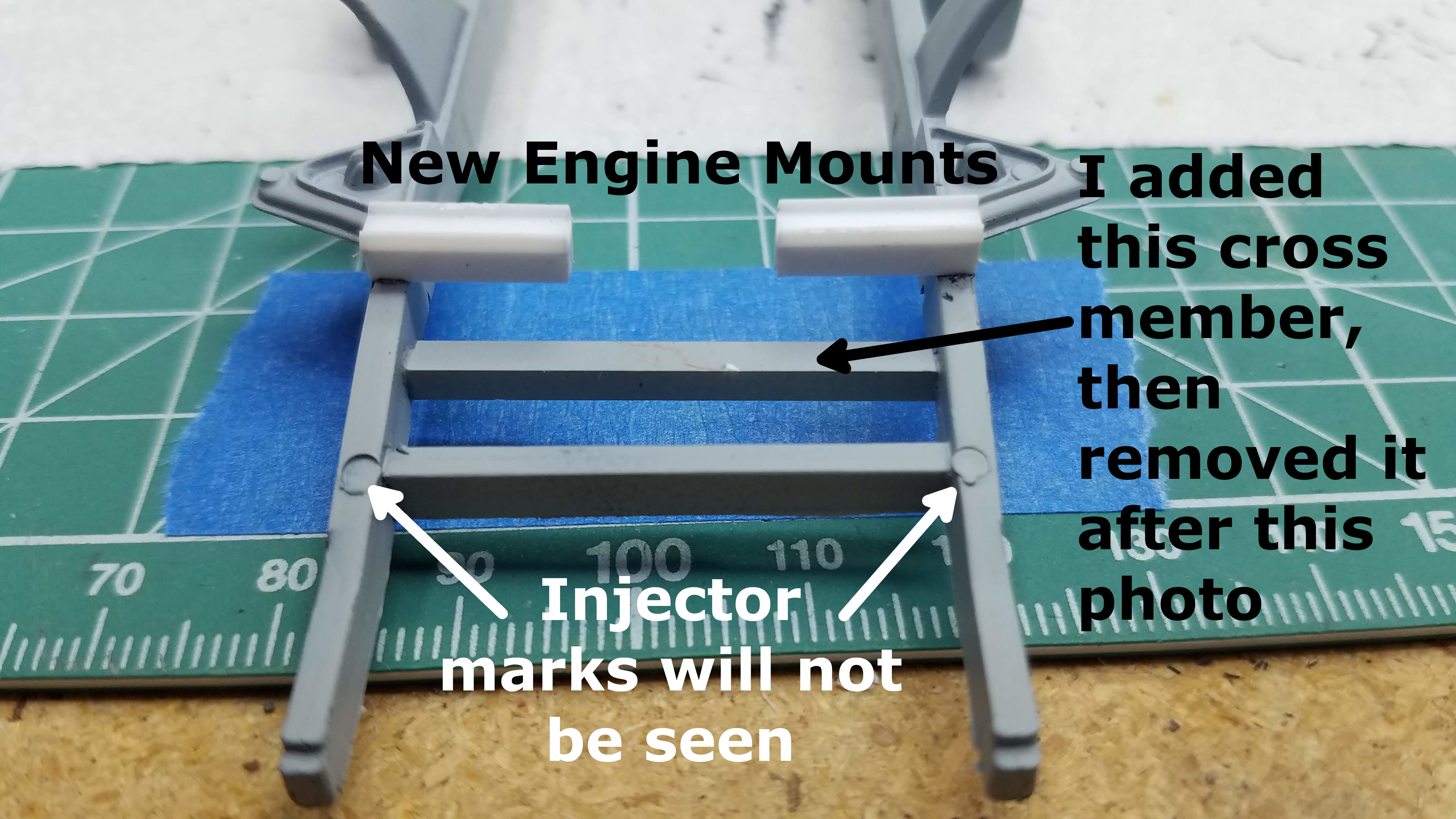
I still needed a way to support the transmission. That was easily solved by adding another cross member in the frame and drilling a hole to accept the alignment pin that is on the transmission housing. I think I got lucky because that gave the engine the correct height so that the drive shaft that came with the truck fit perfectly from the transmission to the rear differential.
30 of 92
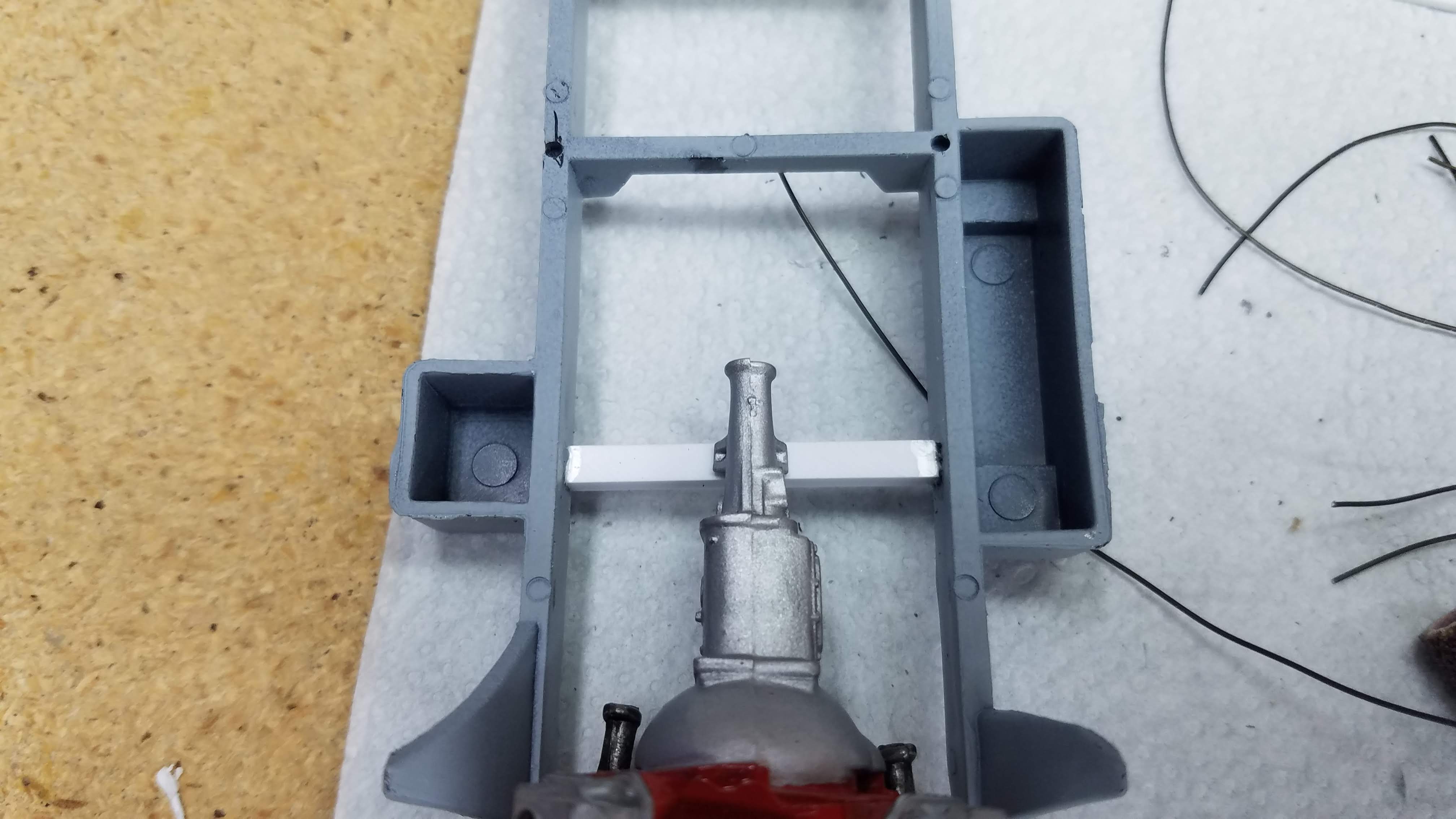
The motor was dry fitted in location so that the engine mounting points were on the engine mounts and the alignment pin of the transmission was in the hole drilled in the new cross member. Everything was seeming to fit well.
31 of 92
The 3rd party pulley's made the engine longer and the crank pulley was setting on this front cross member. To solve that I took a Dremel tool with a cylindrical sanding attachment and cut an arch into the cross member. (In a real truck I wouldn't have done this because it would take some of the strength away from the cross member, but hey...this is a model
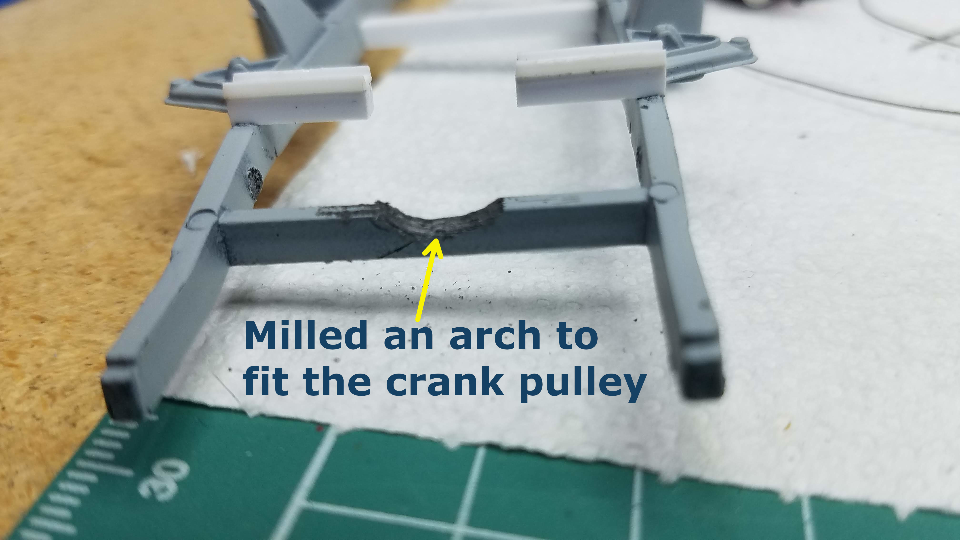
32 of 92
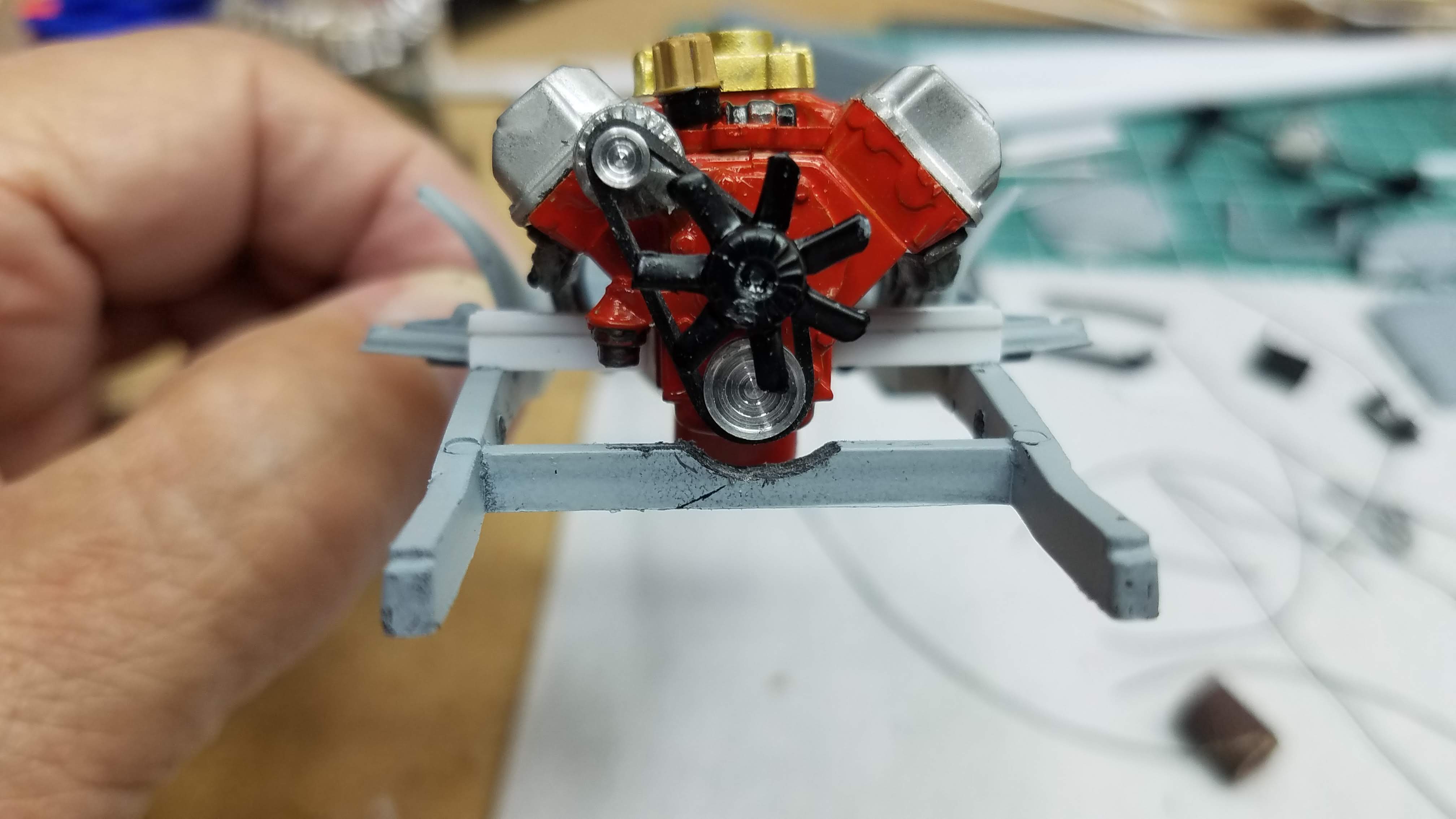
This shows the Hemi engine sitting on the motor mounts and the clearance for the crank pulley. I like the way the engine sits in the frame, nice and level.
33 of 92
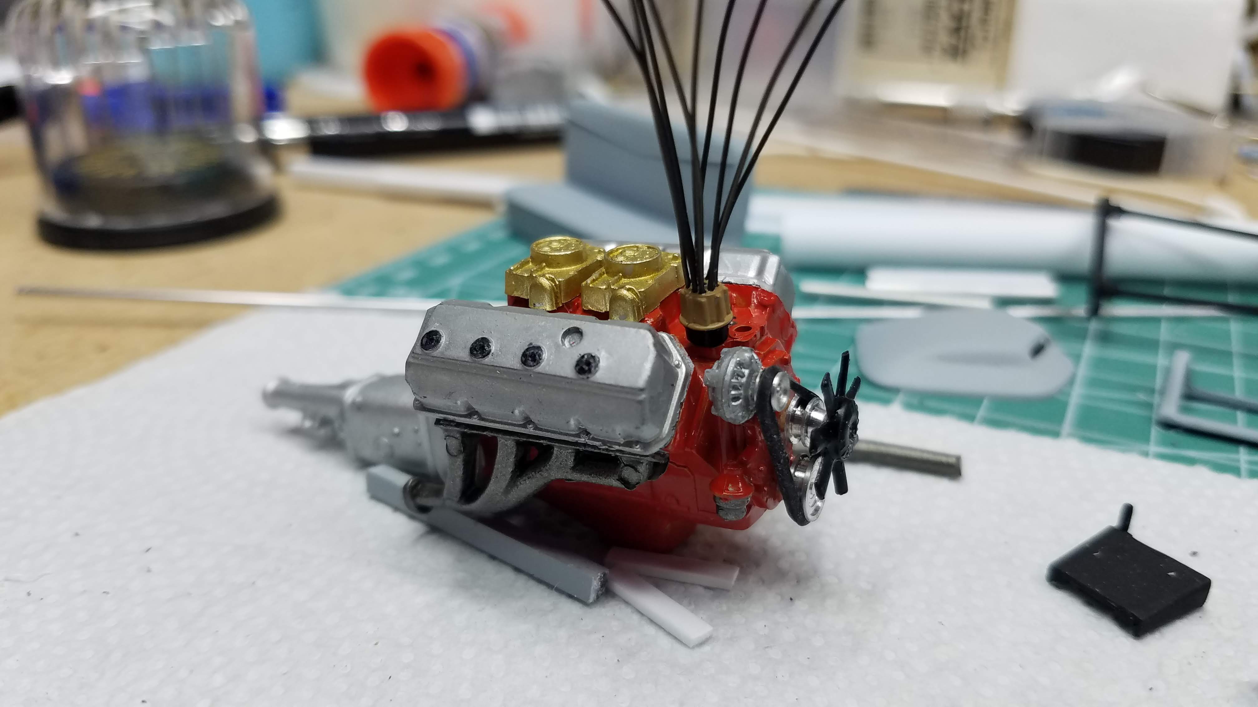
Spark plug and coil wires have been installed in the distributor and super glued in place. When the glue is thoroughly dry the wires will be bent, shaped and inserted into the valve cover caps.
34 of 92
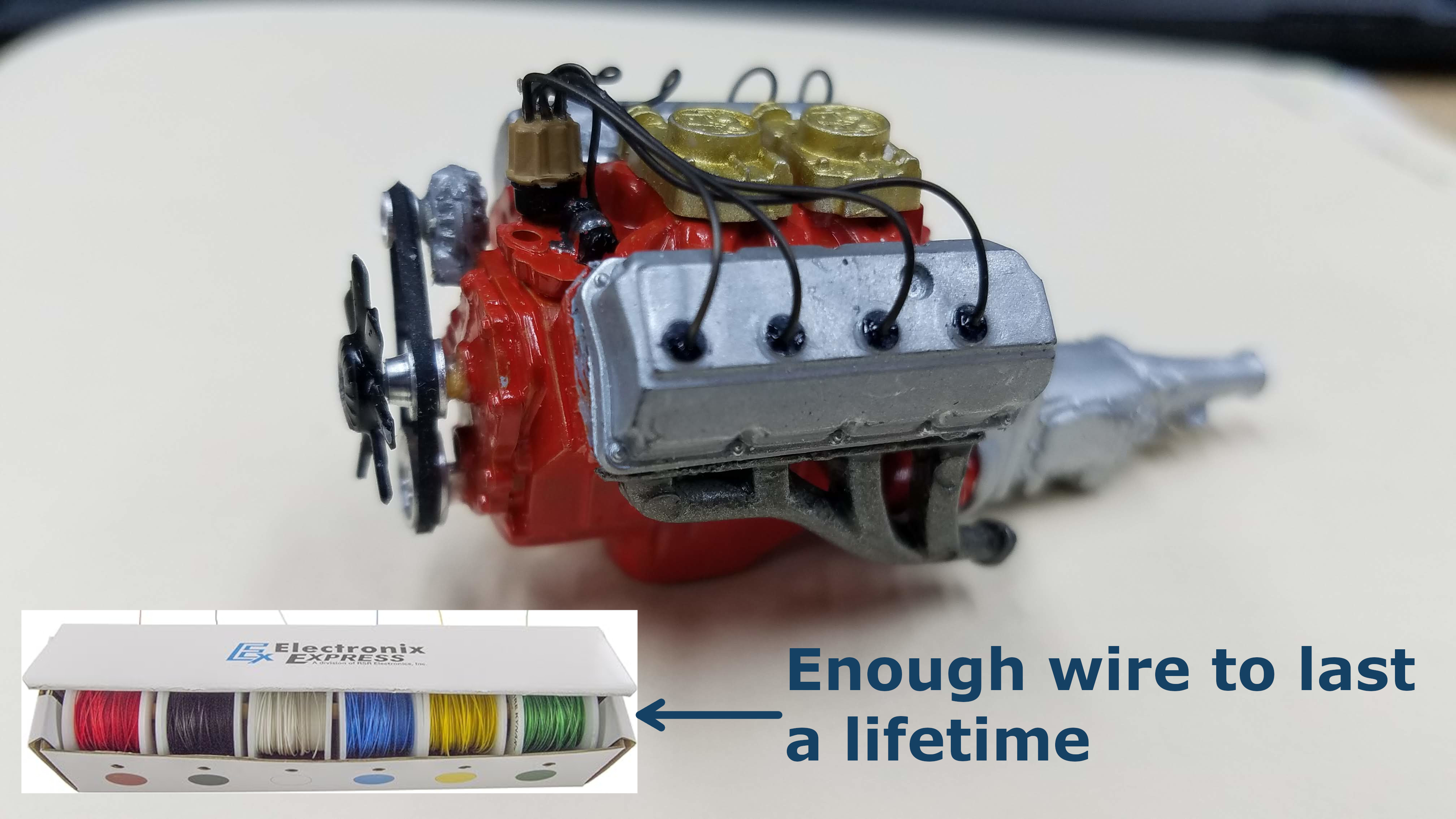
I painted the coil and its mounting bracket then routed the spark plug wires to the value covers. The spark plug wire I use is not from a model supplier. I bought spark plug wire one time from a model car supplier and realized it is nothing more than electrical wire. I measured an actual, typical, spark plug wire and than calculated the scale for 1:24/1:25. Using 30 AWG (American Wire Gauge) solid wire with Kynar insulation (wire wrap wire) is equivalent and a lot cheaper. I bought a box containing six 100' spools for $46.00. If my calculations are correct, that's $0.077/foot. Six different colors; red, black, white, blue, yellow, and green. That's enough wire to last me the rest of my life. The inset picture shows a picture of the box of wire.
If you're interested in taking a closer look at this wire
and/or ordering some for yourself, it's available on Amazon.
Here is a link:
EX ELECTRONIX EXPRESS Electronix Express 27WK30WWR100 Solid
30 Gauge Wire Wrap, Kynar Insulated Wire Kit with 6-100'
spools
35 of 92
Another picture of the wired engine. This time from the right side.
36 of 92
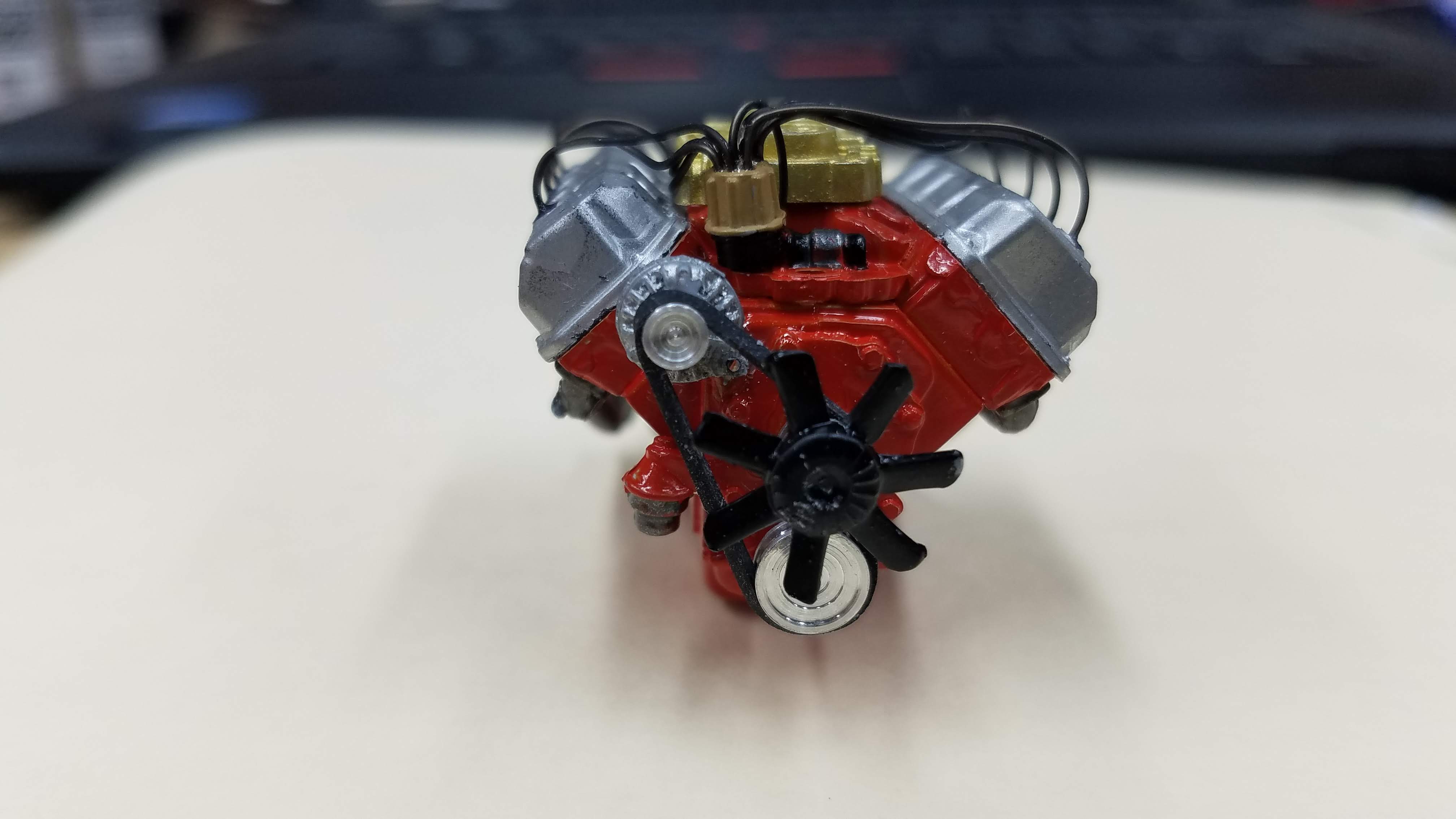
Another picture of the wired engine. This time from the front.
37 of 92
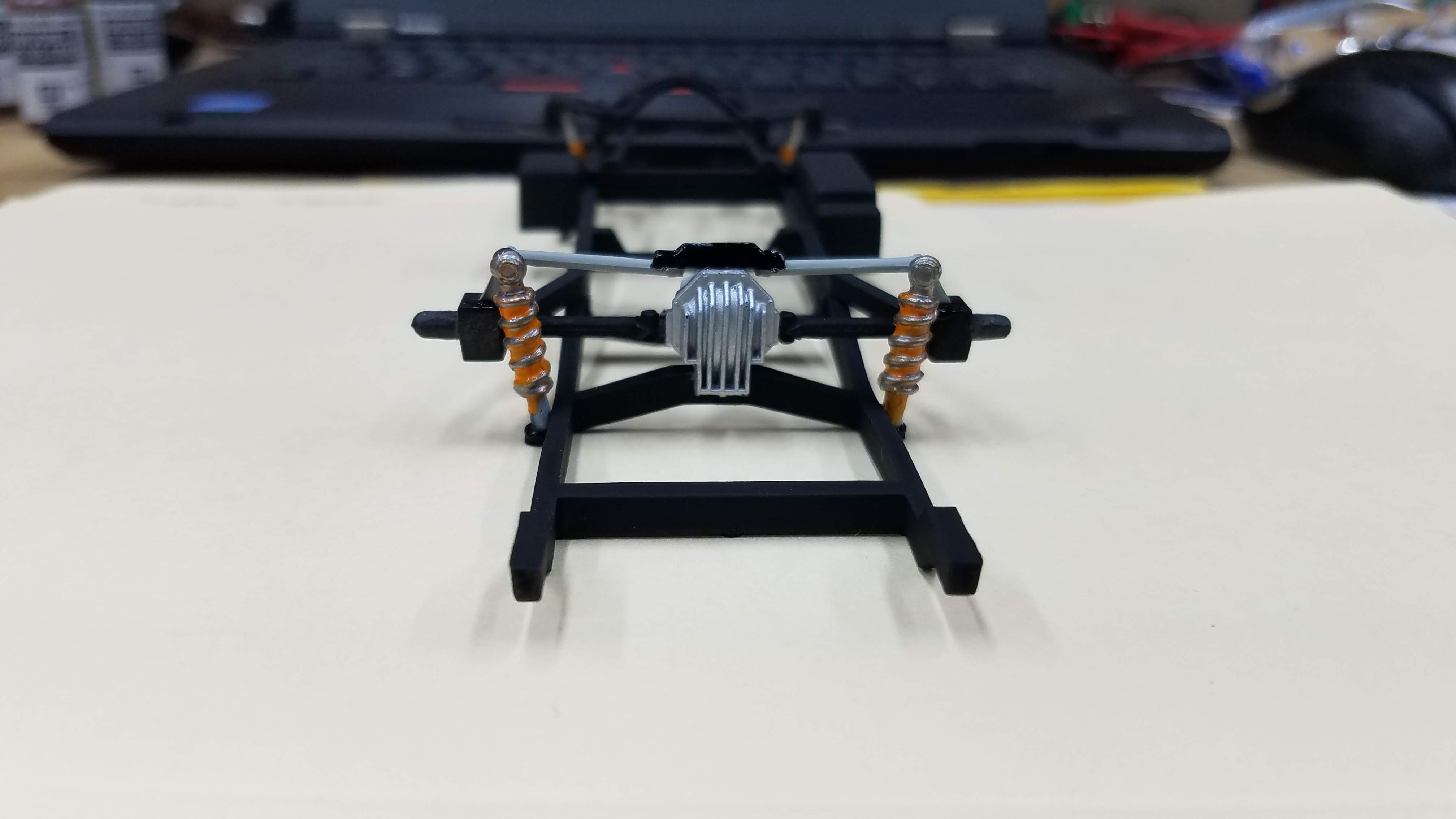
The rear axle, differential and coil spring over shocks is installed.
38 of 92
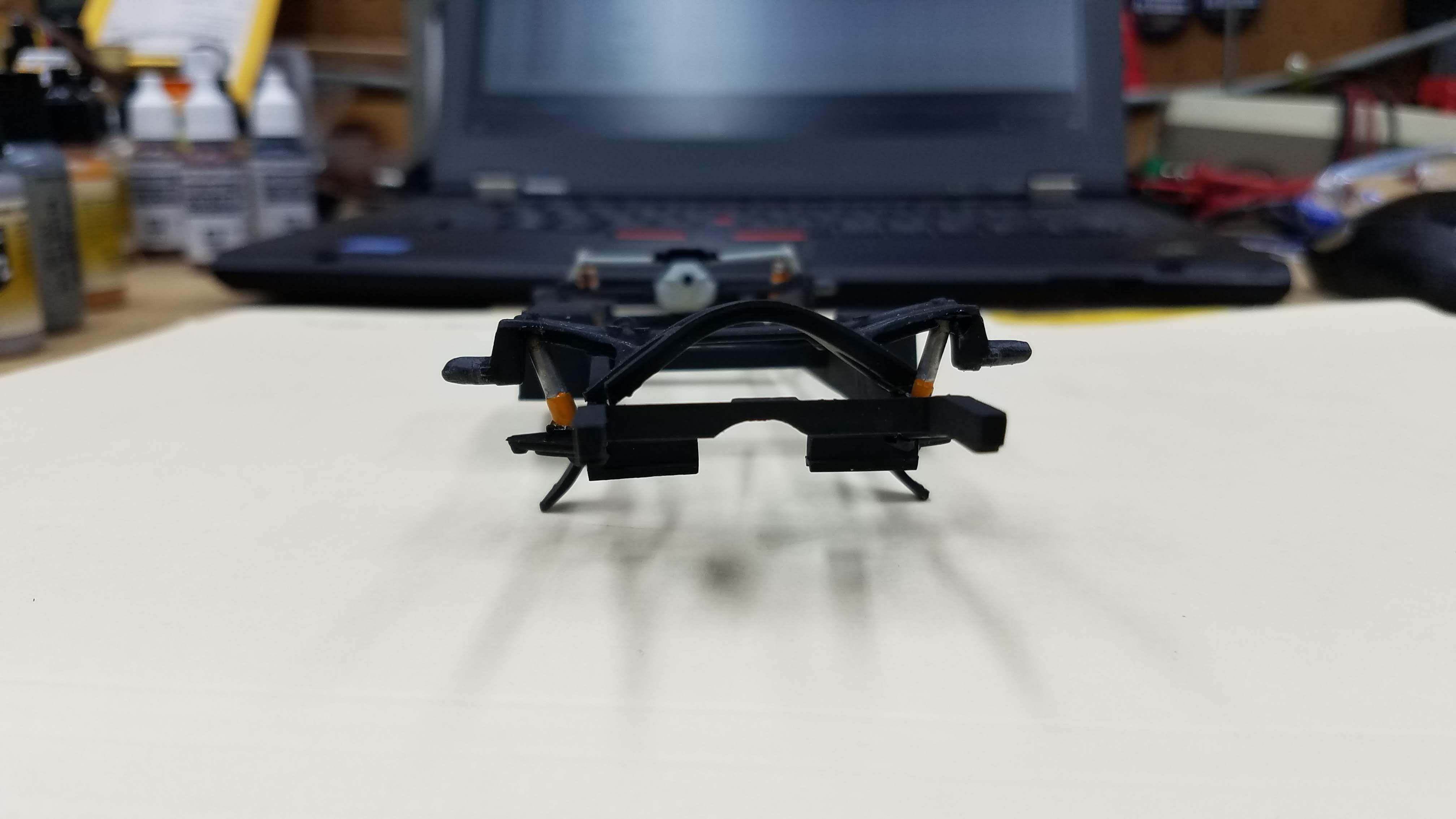
Front shocks are installed.
39 of 92
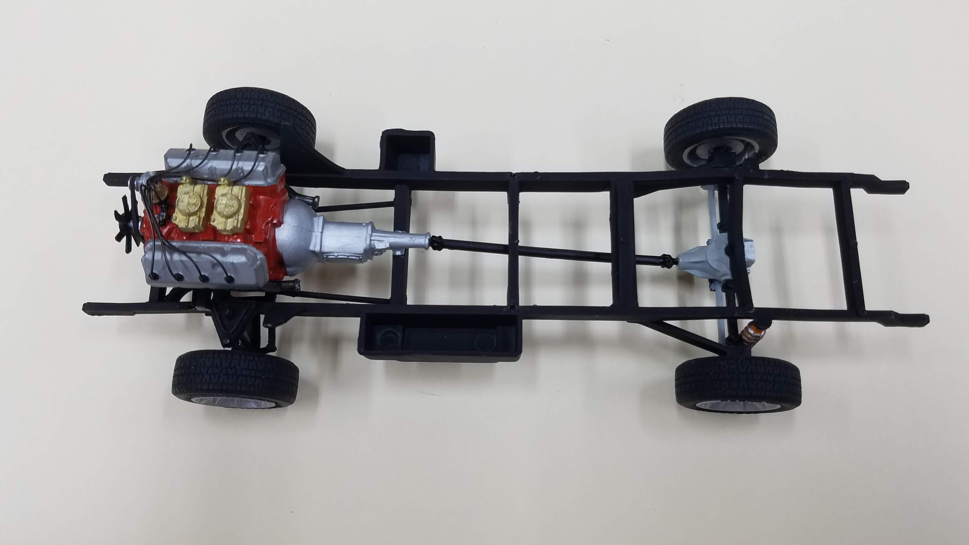
View of the frame bottom with rear axle, differential and suspension installed along with the front steering linkage.
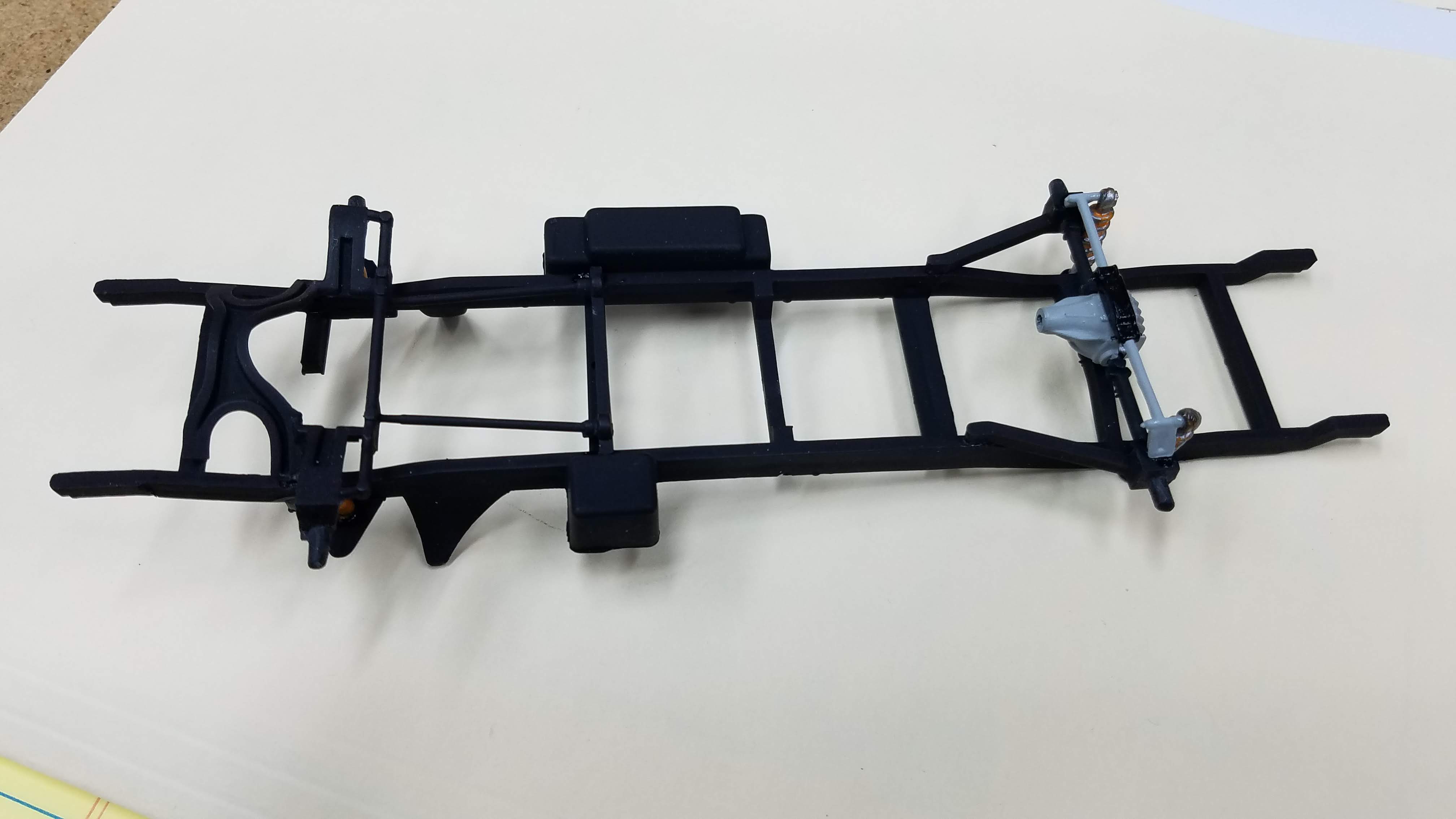
40 of 92
Side view of the frame. (Not sure why I took this?)
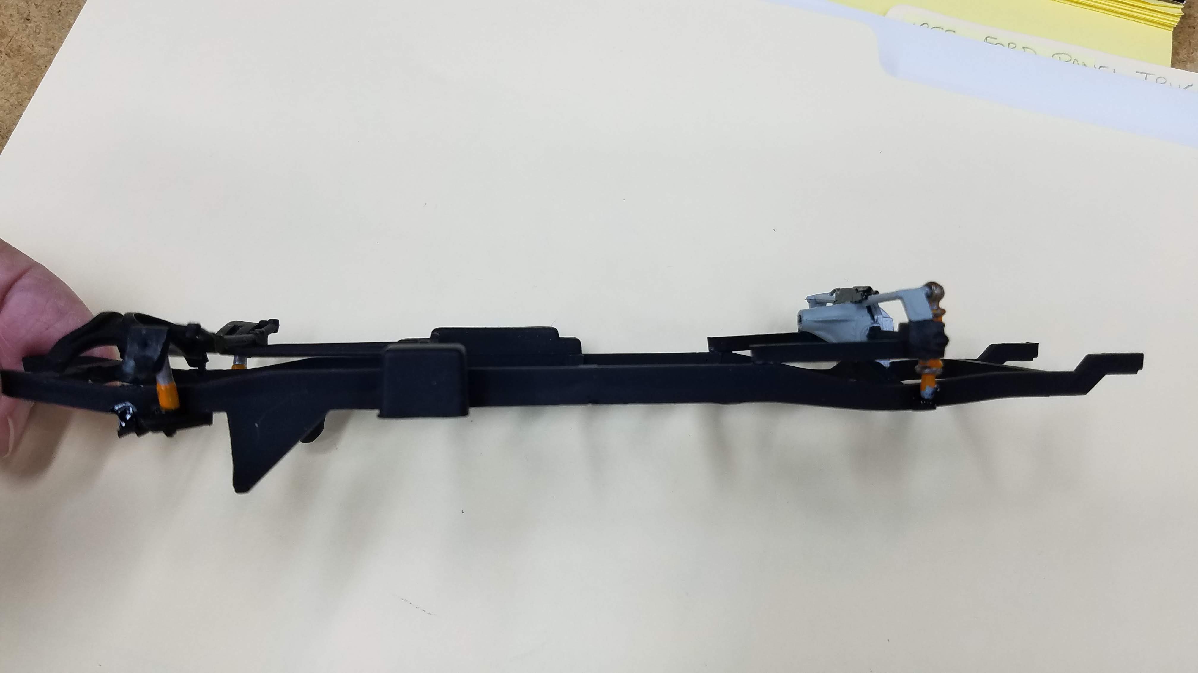
41 of 92
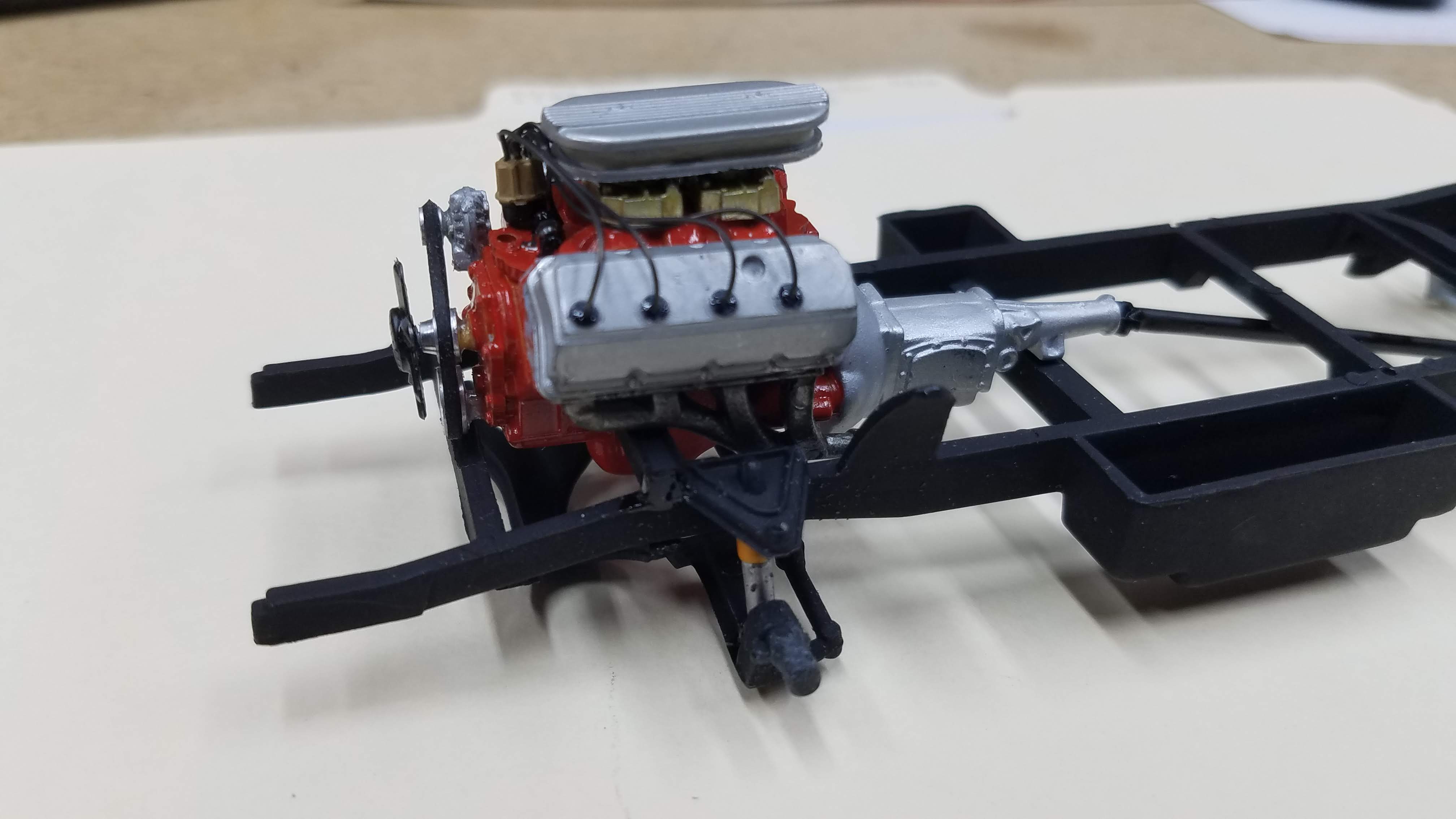
Engine is mounted on the frame.
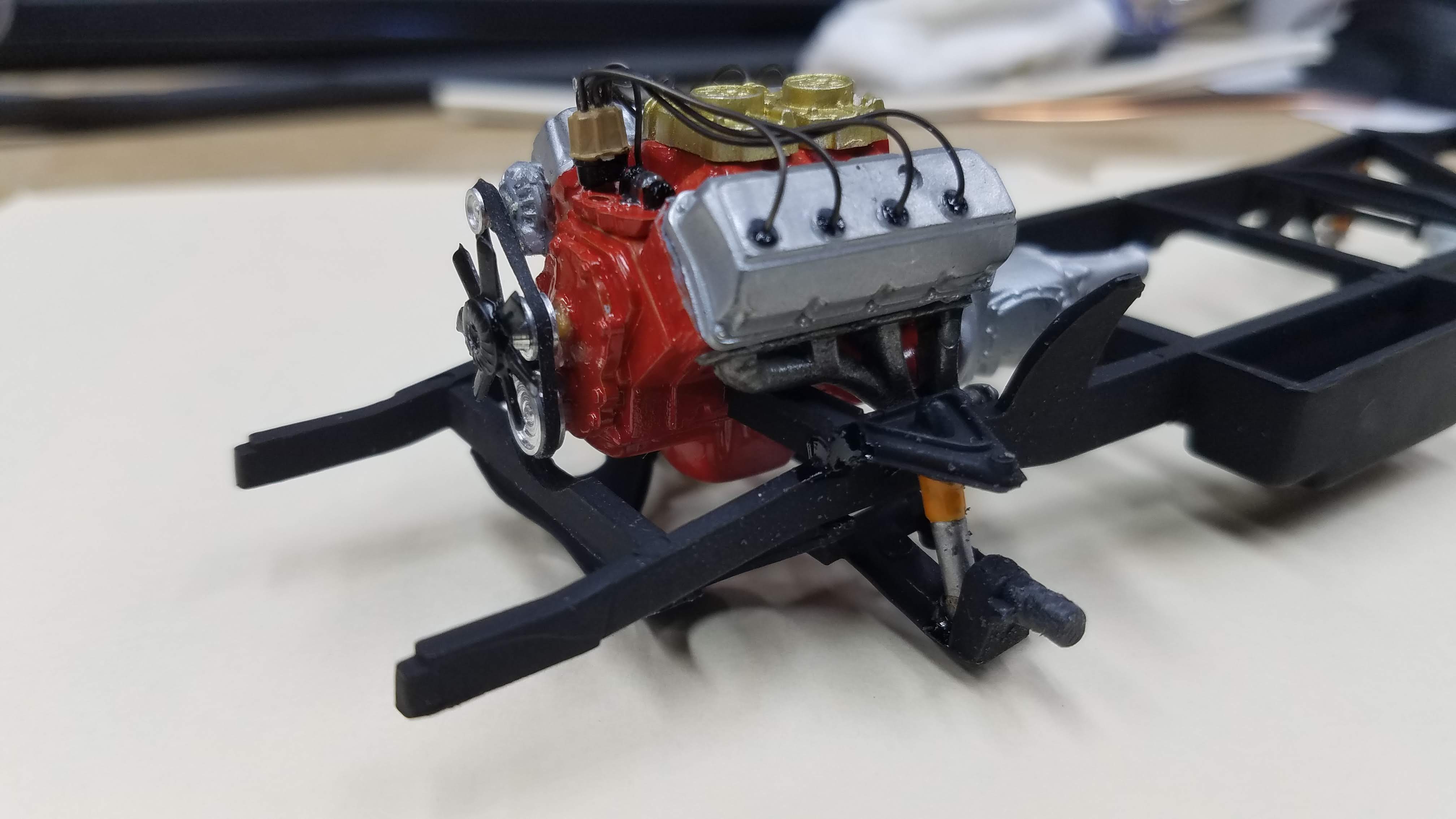
42 of 92
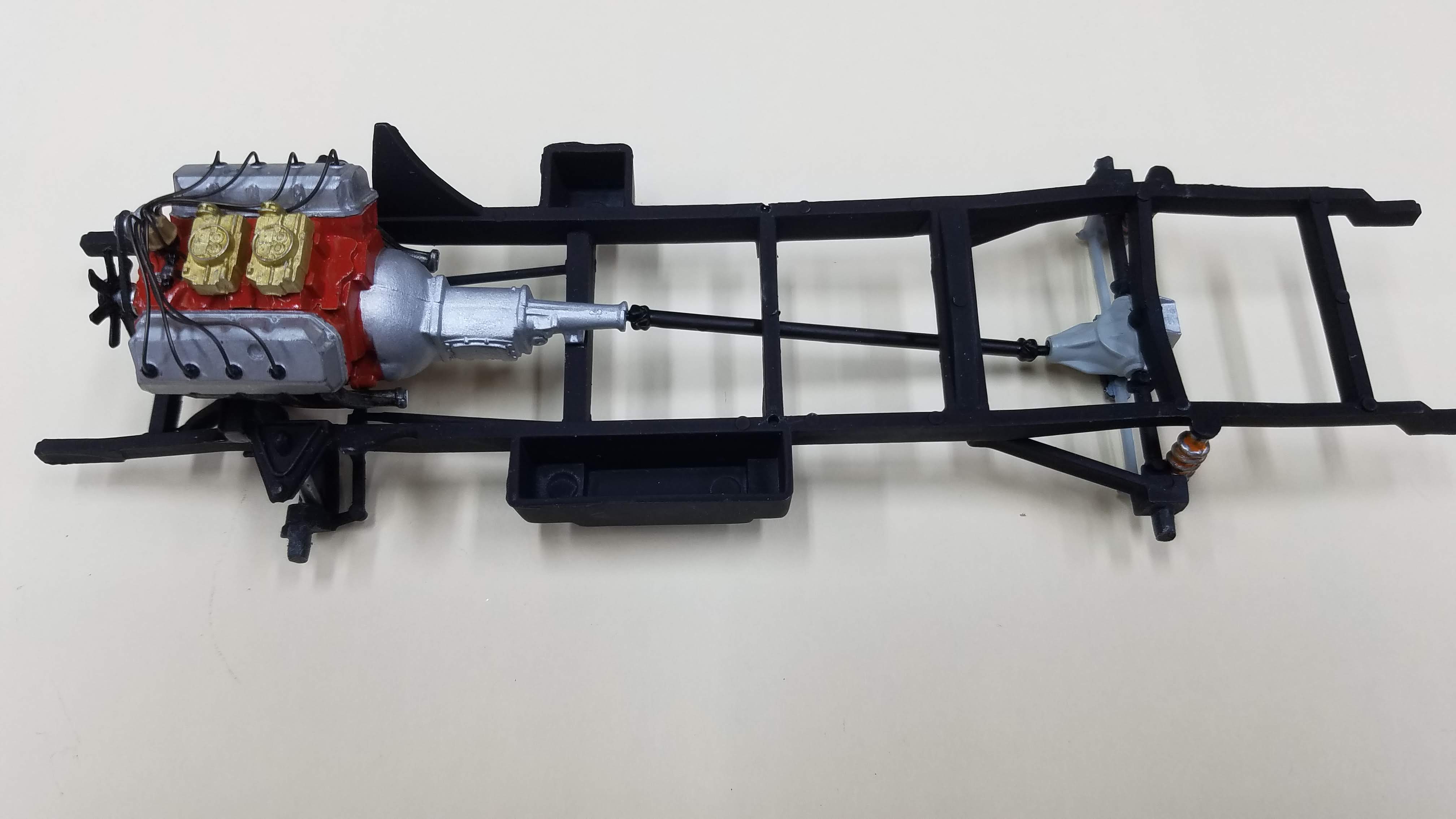
Top view of the frame with the engine mounted.
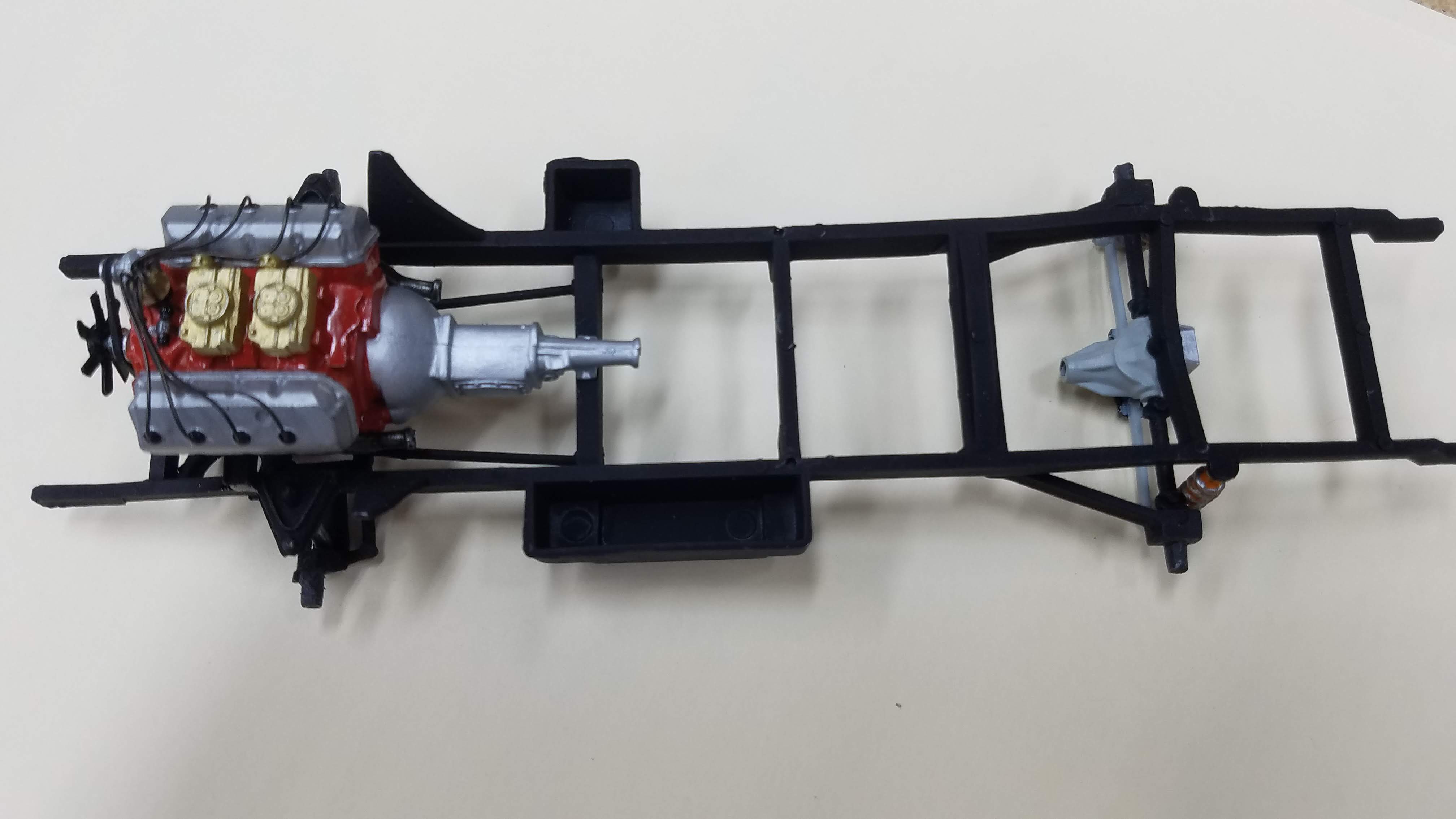
43 of 92
The drive shaft has been installed.
44 of 92
The air cleaner is installed on the engine. The air cleaner is from the '55 Ford engine that came with the kit.
45 of 92
Top view of the frame with the completed engine and drive shaft installed.
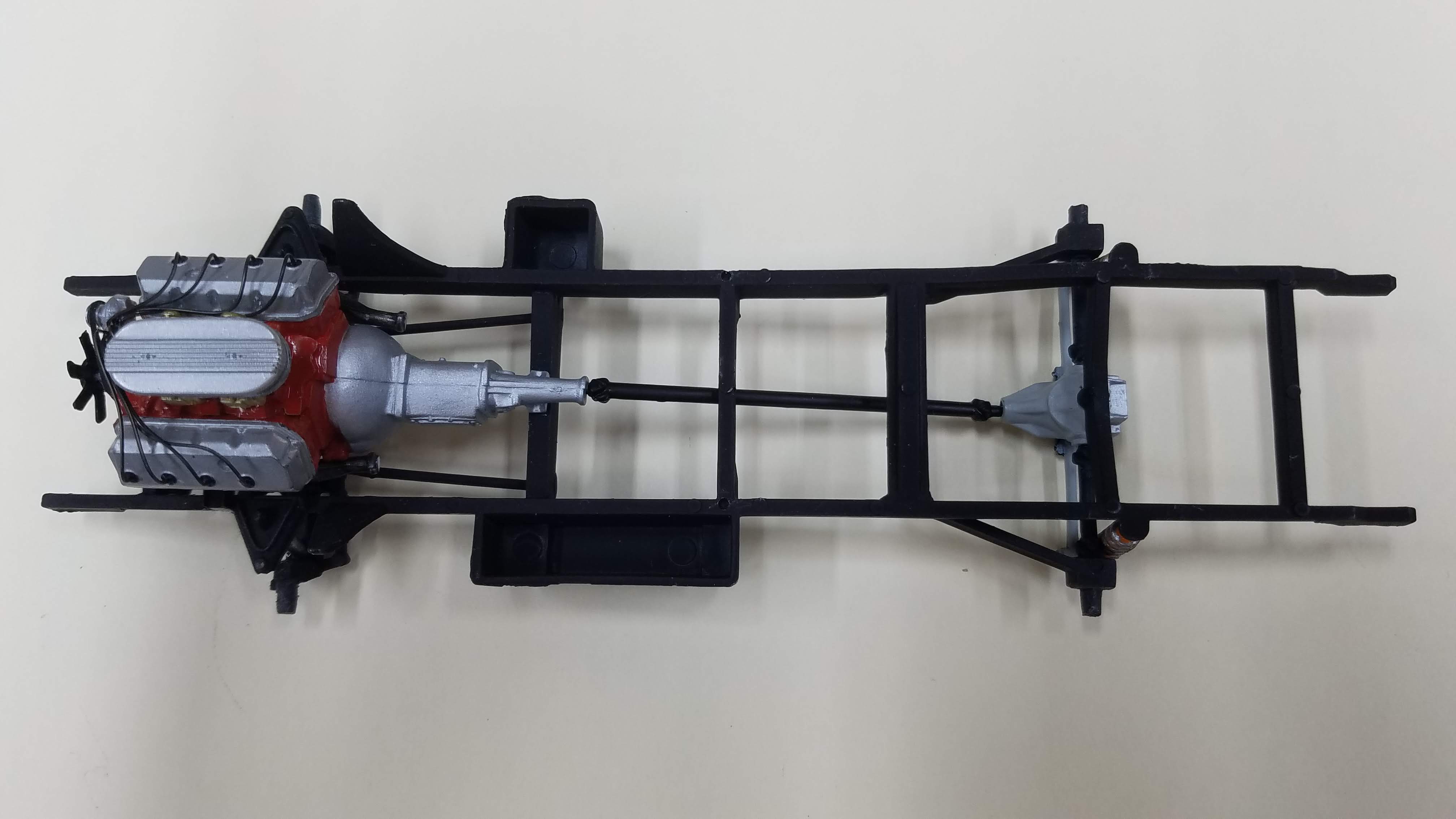
46 of 92
Side view of the wheels and tires are installed on the frame.
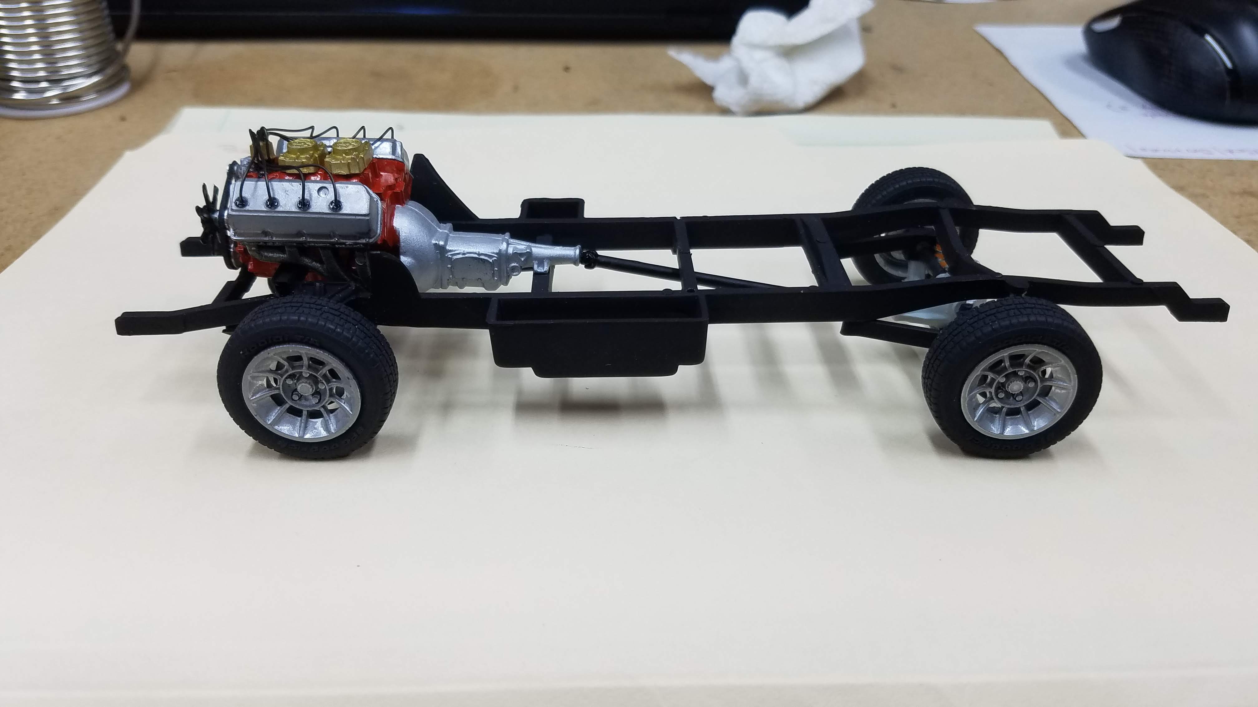
47 of 92
Top view of the chassis with the wheels and tires installed.
48 of 92
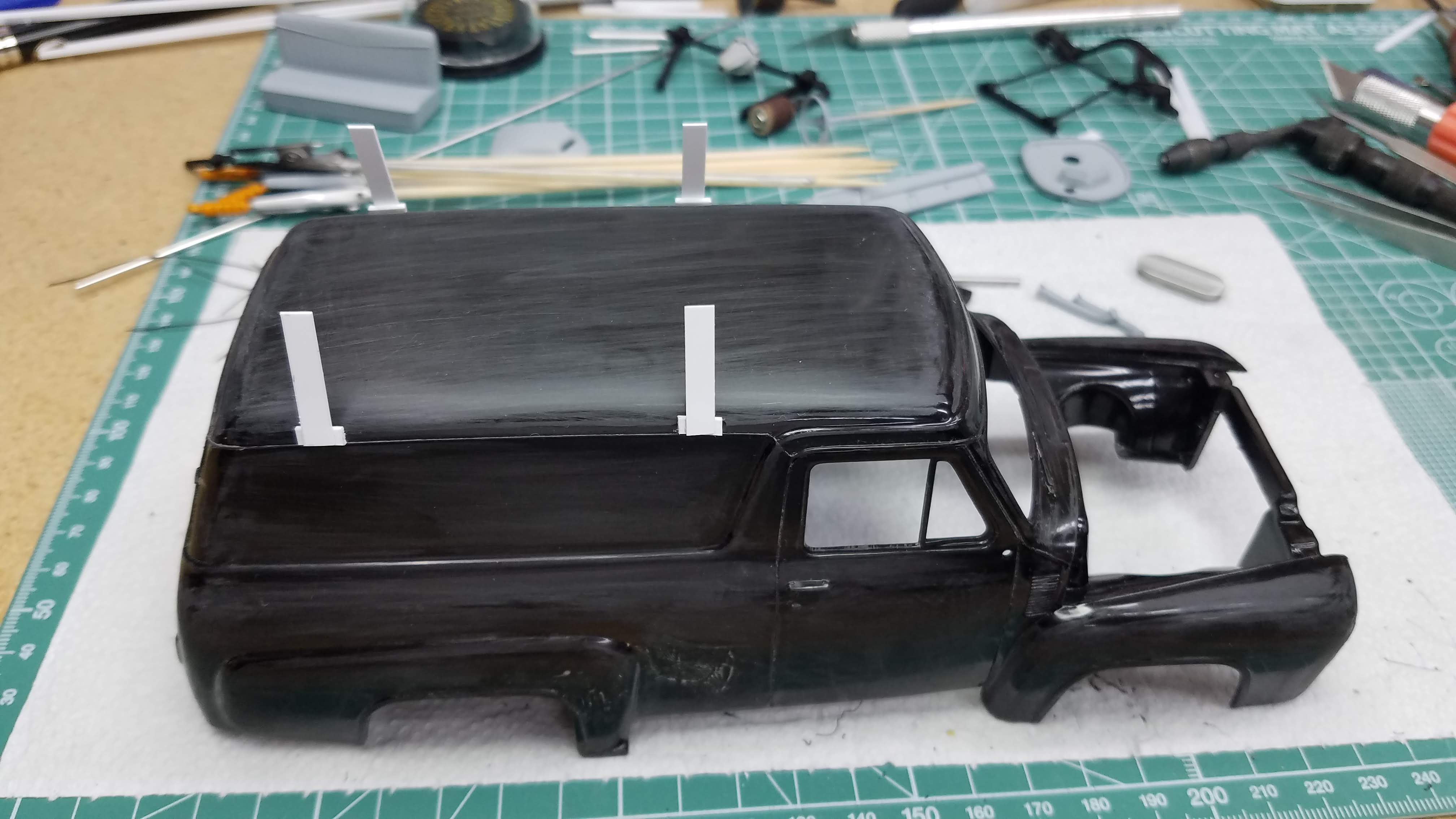
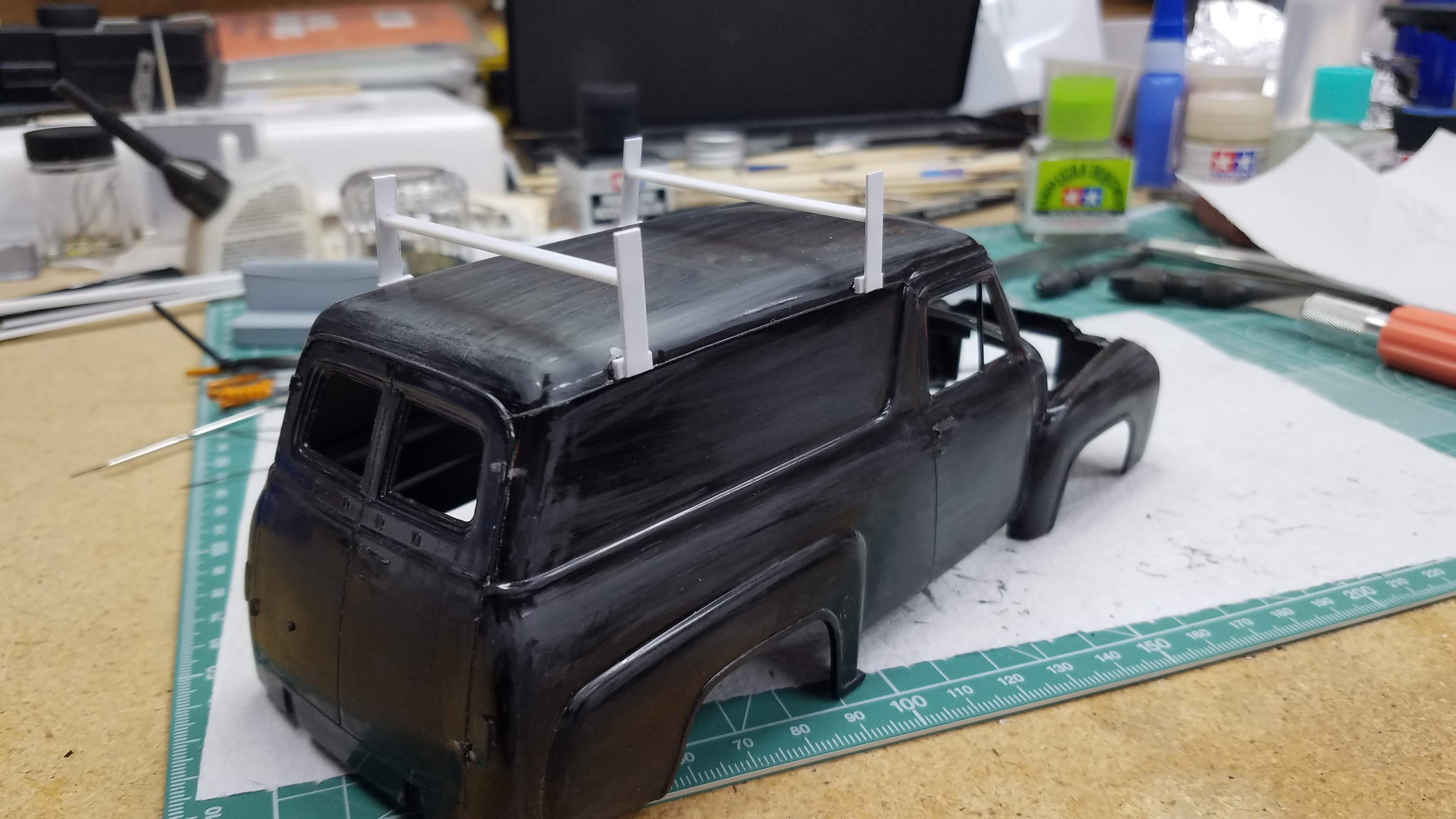
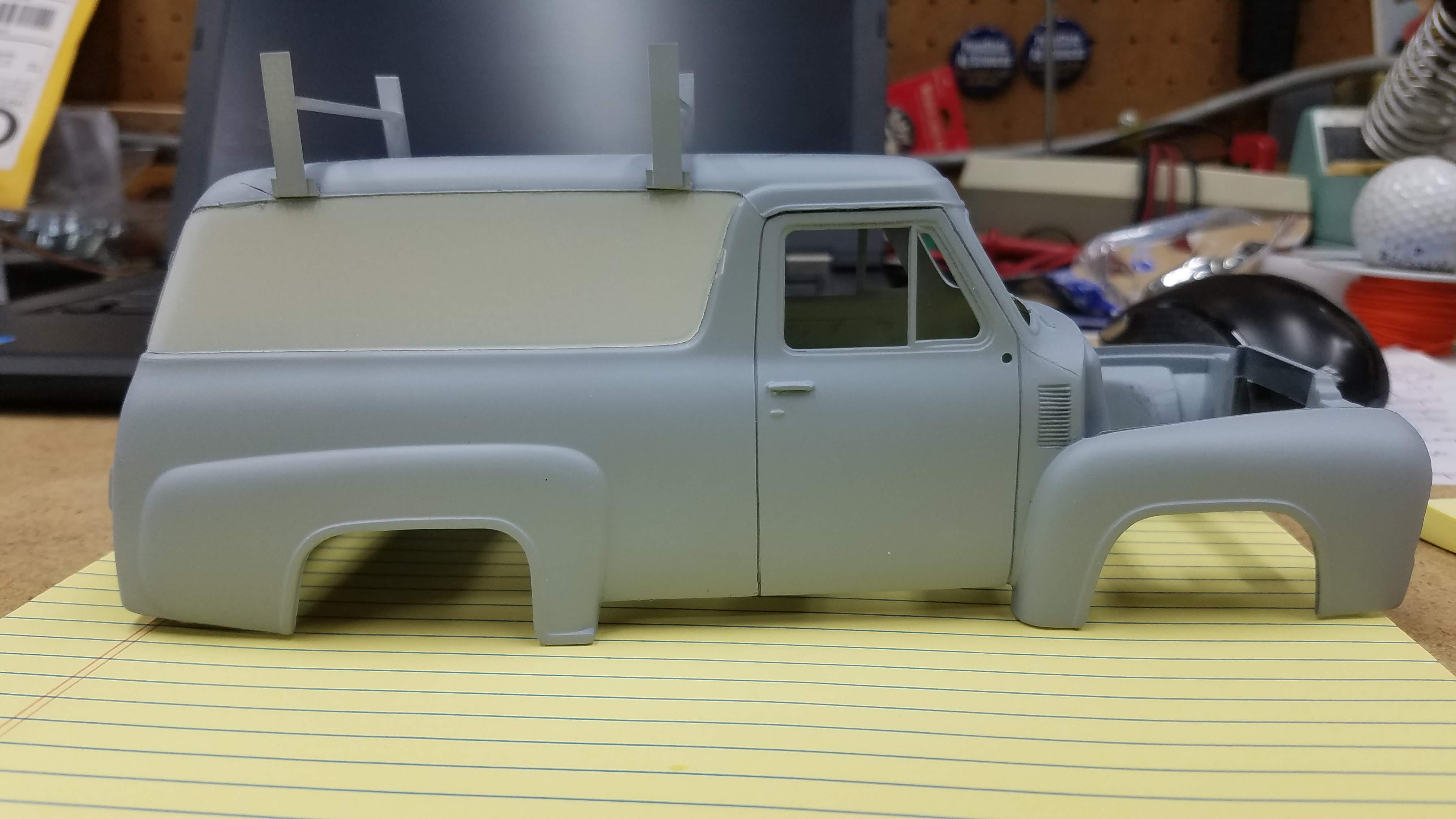
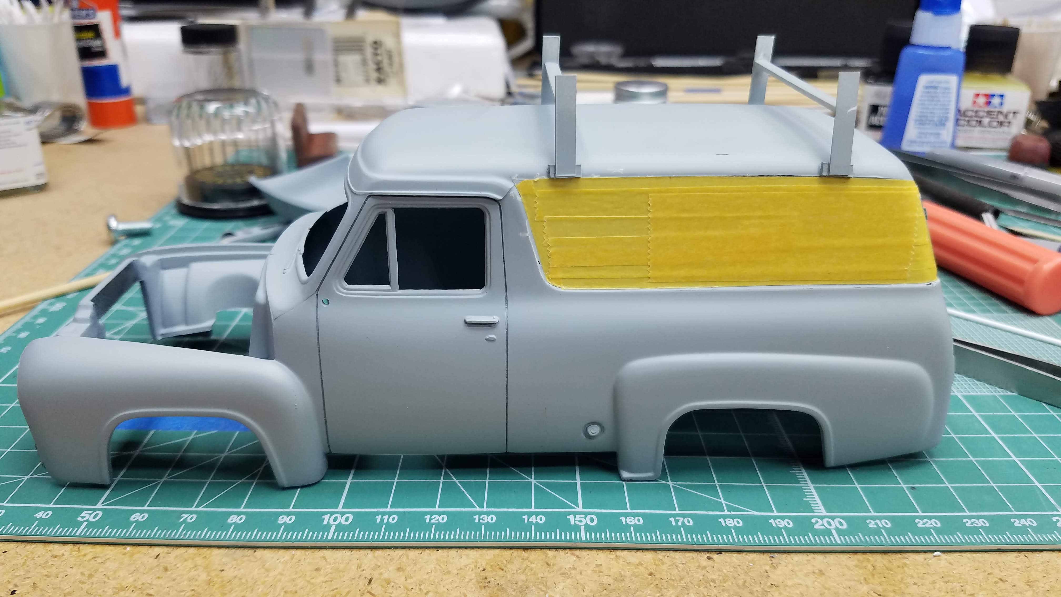
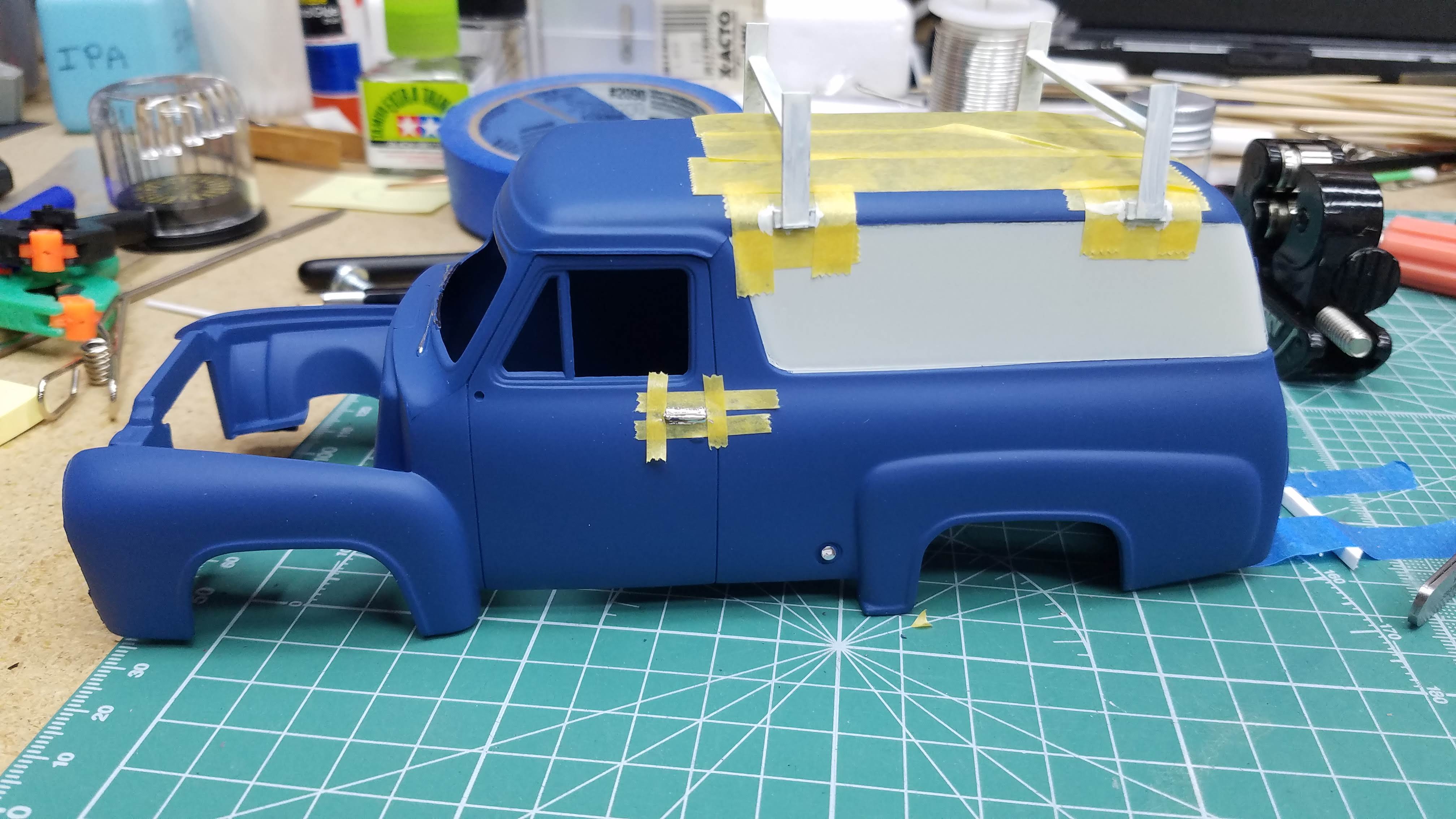
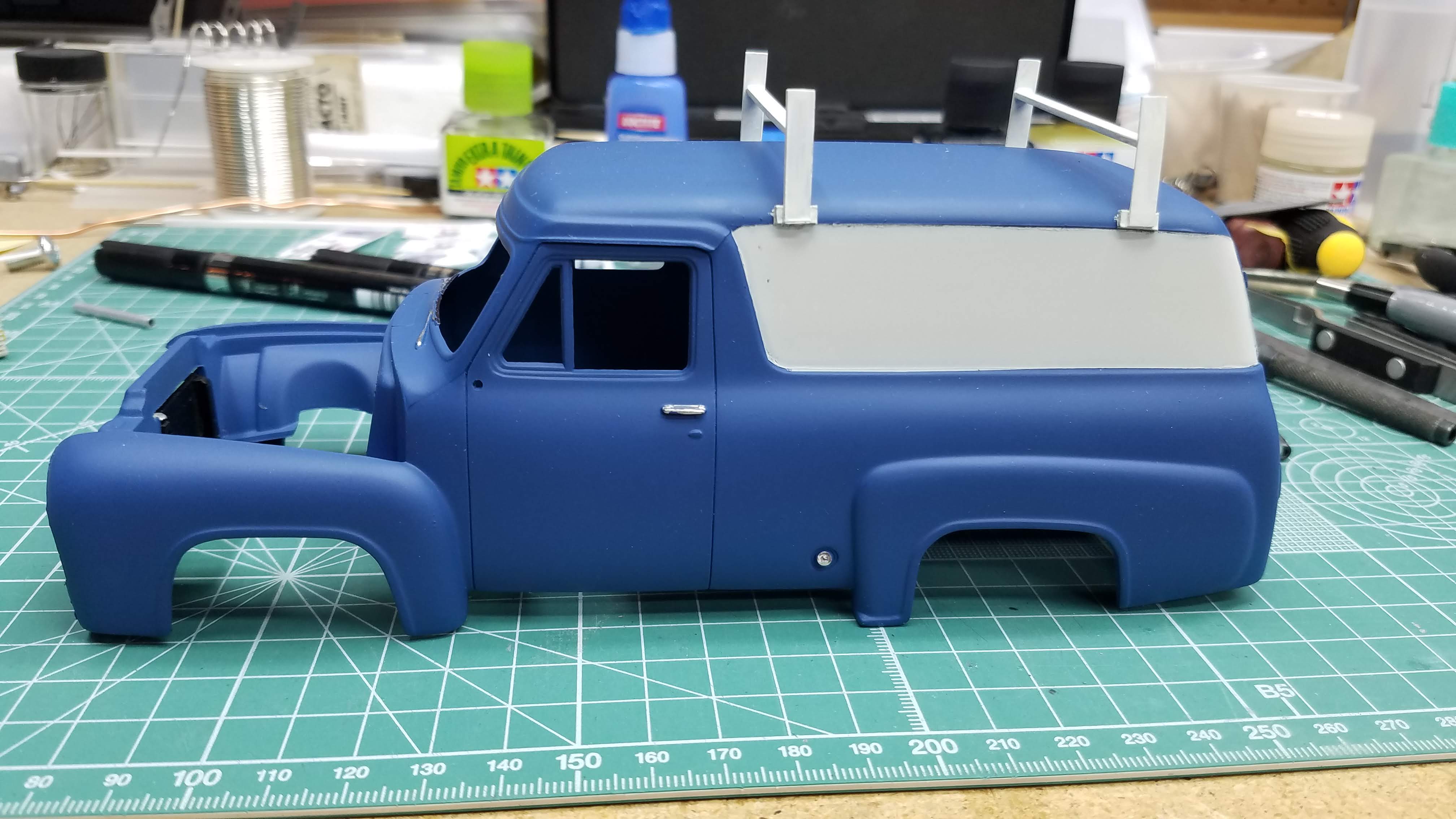
The body was sanded just enough to get most of the shine off of it. Then I mounted the uprights for the roof racks. All they are, are some small strips of 0.020"/0.508mm styrene that I glued to the sides of the roof line. This was the first time I ever build my own roof racks. They worked out fine, but next time I will definitely pin them to the roof edge before glueing them so they have more rigidity. Later during the build, one of them started leaning in toward the roof. Pinning would have prevented that from occurring.
49 of 92
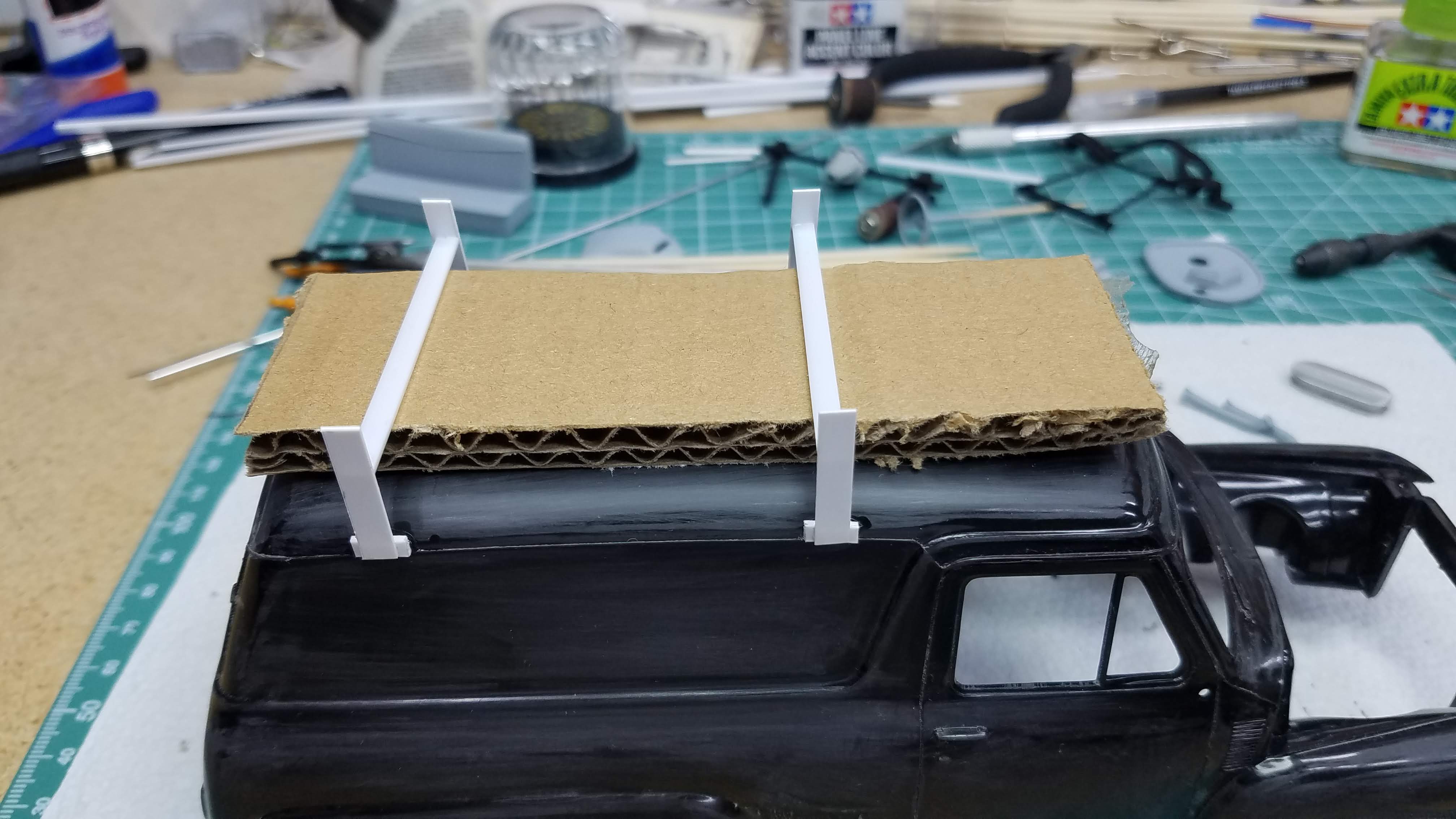
I used a piece of thick cardboard to keep the spacing between the cross members of the roof rack and the roof parallel to the the roof. The cardboard also supplied support to the 0.125"/3.175mm channel I used for the cross members while the glue was drying.
50 of 92
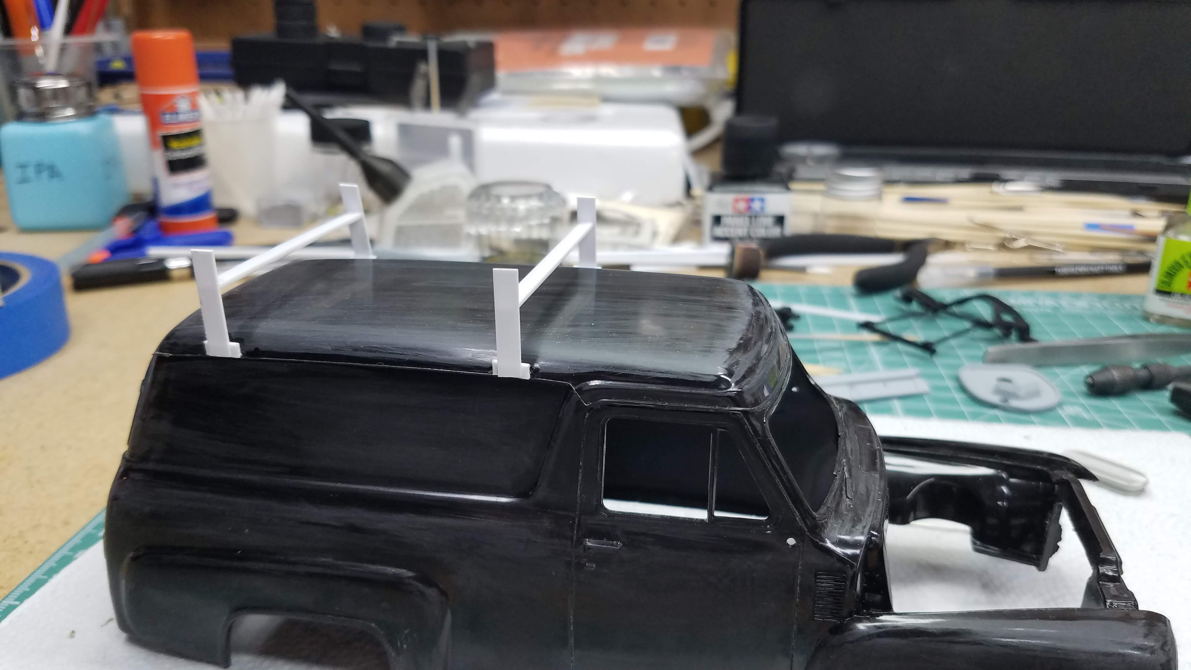
Side view of the installed roof racks racks.
51 of 92
Back view of the installed roof racks.
52 of 92
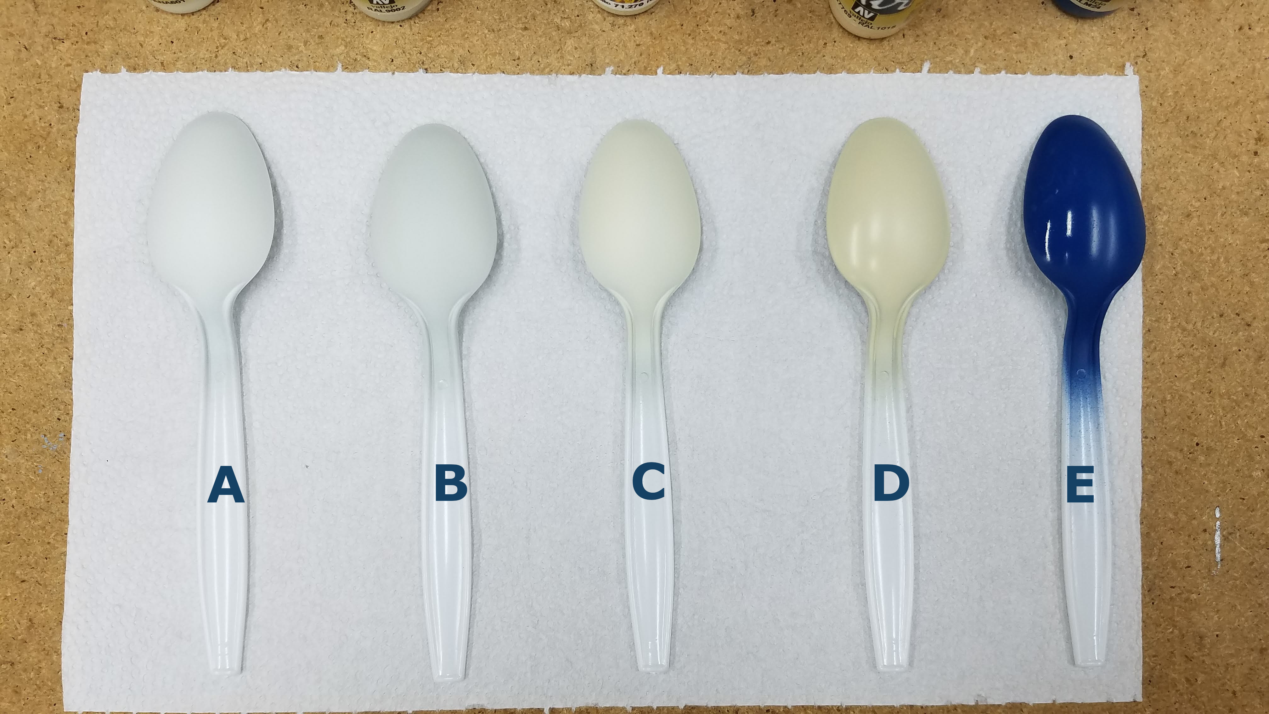
Before continuing with the build I wanted to decide what color white I would be using for the side panel and for the grill and bumpers. I already knew I was using blue for the main part of the body. I shot some test spoons and made my decision as outlined here. The spoons have a coat of Vallejo 70.510 Gloss Varnish (clear coat). I had never used this 'Varnish' so I guess we'll see:
-
Vallejo 71.279 Insignia White
I used this for the side panels where the main decal would be located and for the background of the dash board instrument cluster. -
Vallejo 71.119 White Gray
I used this for the grill and bumpers and the bottom half of the dash board. -
Vallejo 71.270 Off-White
Did not use this. -
Vallejo 71.132 Aged White
Did not use this. -
Vallejo 71.266 Dark Blue RLM24
I used this for the body, the top of the dash board, the wheel wells in the back of the truck and the steering wheel.
53 of 92
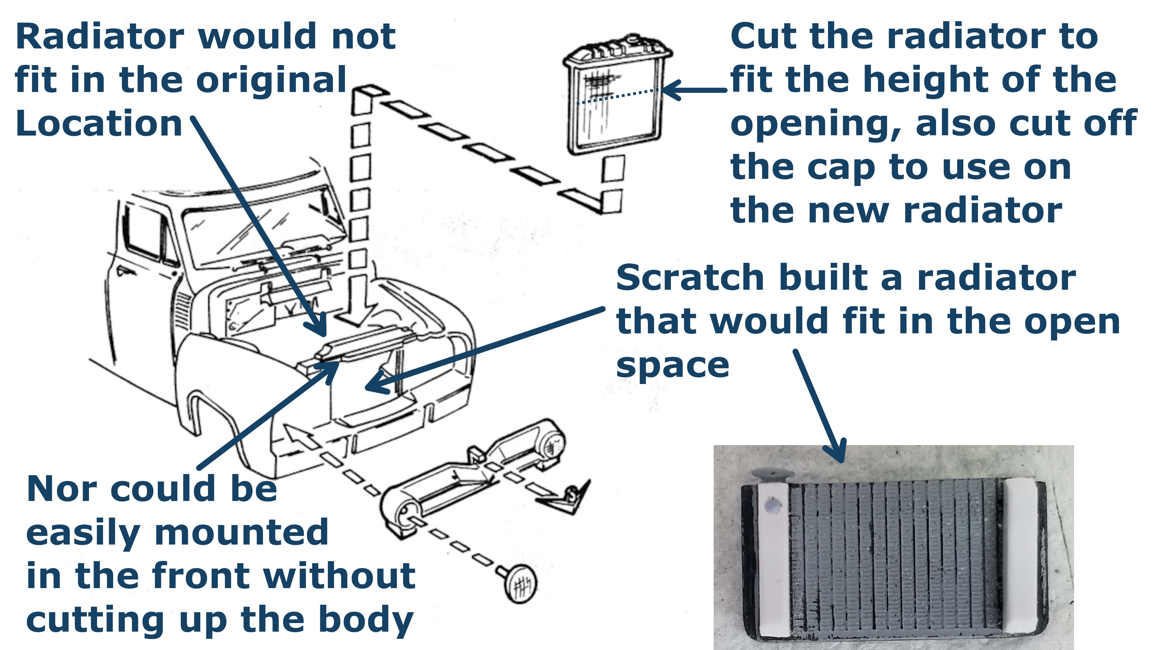
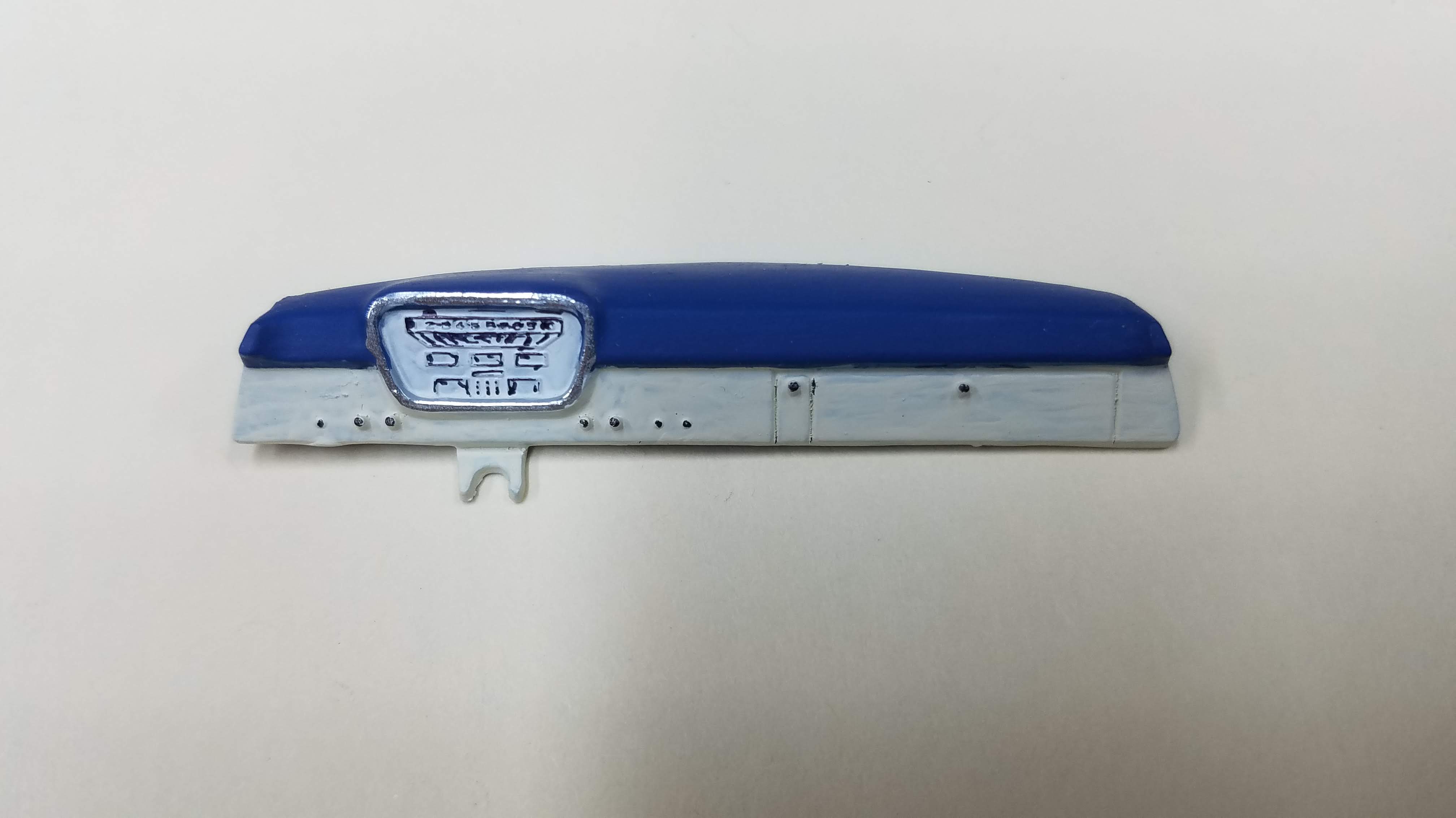
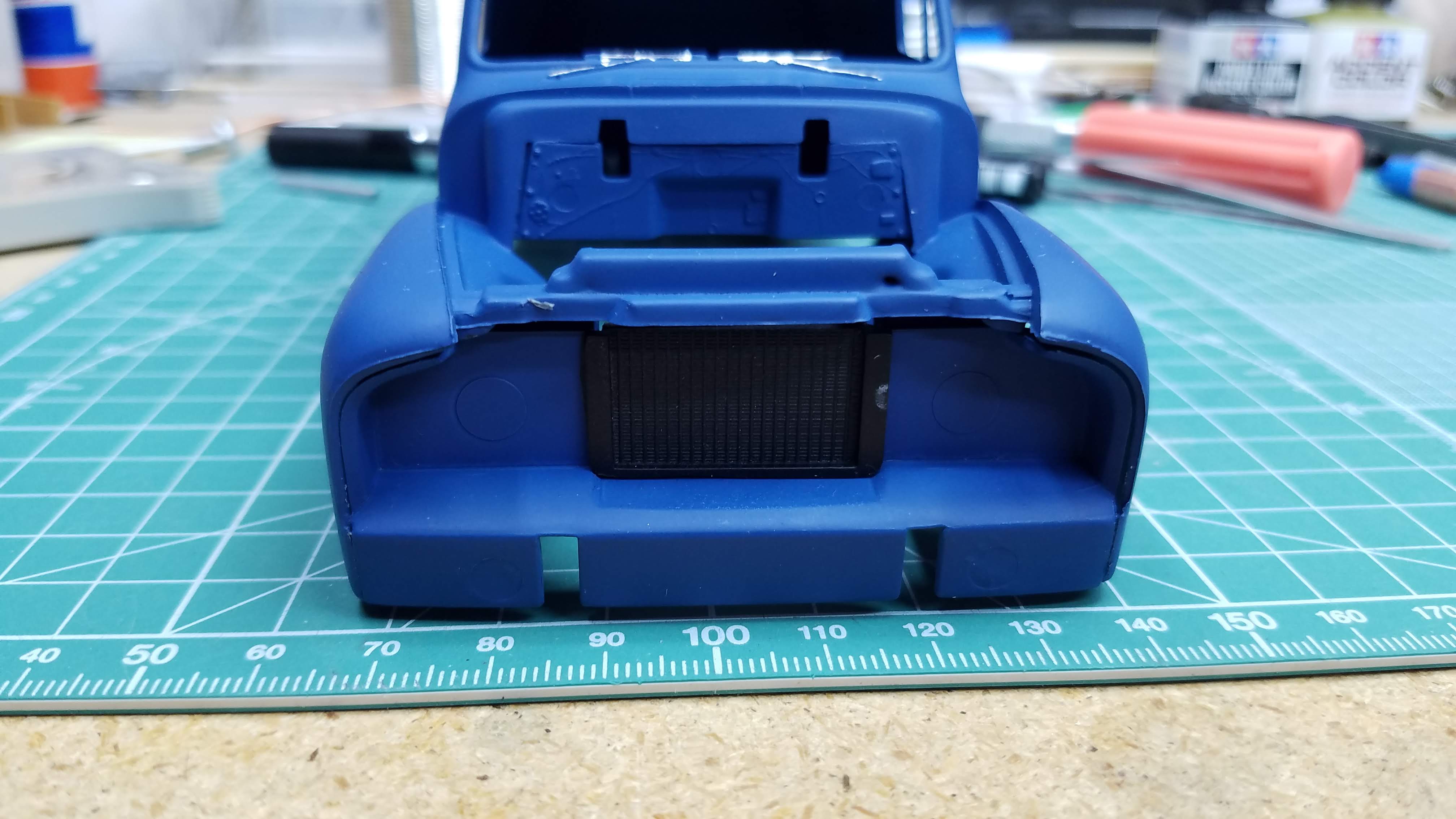
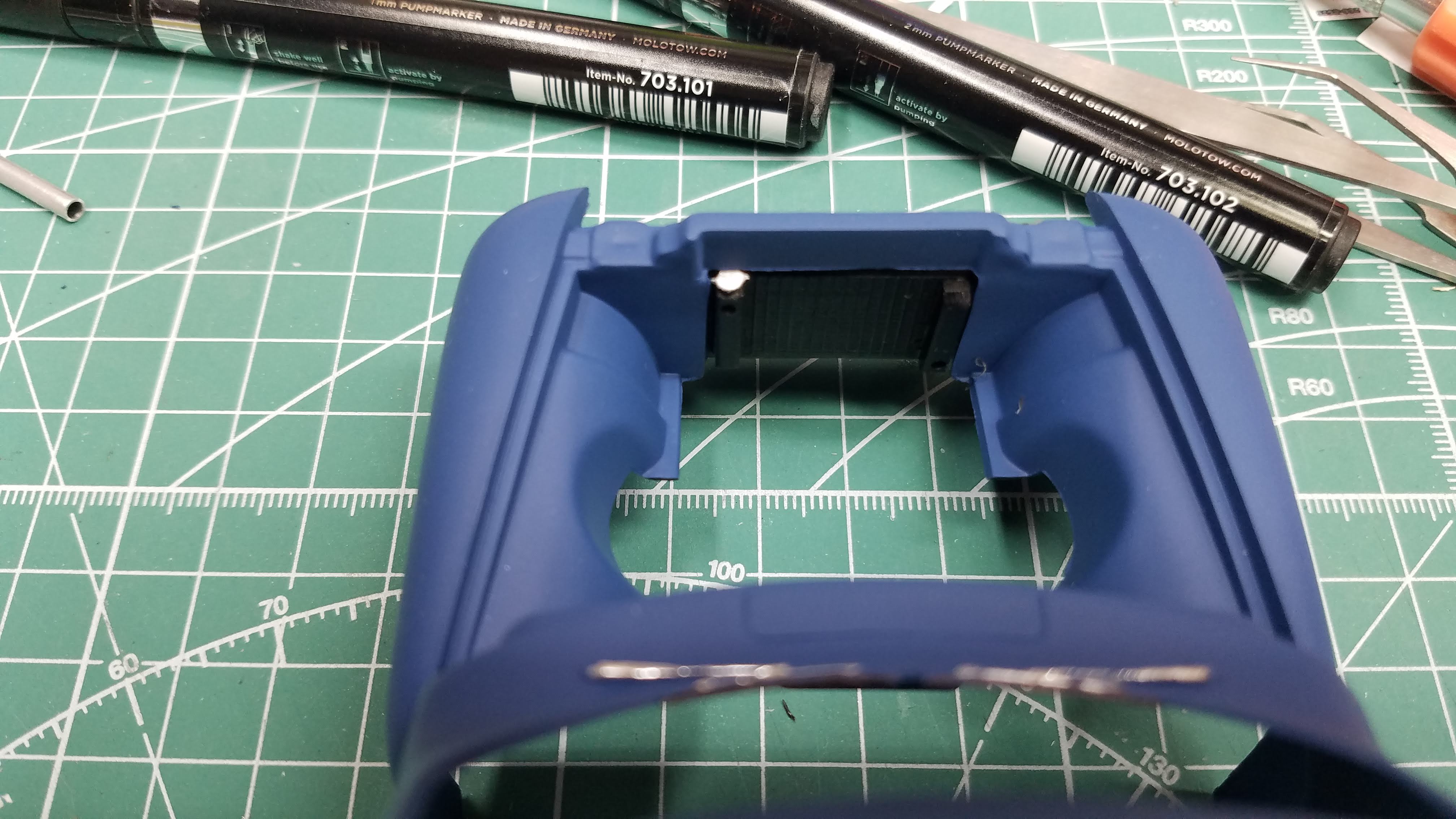
By installing the after marked engine pulleys the engine was long enough that the kit radiator did not fit. I thought about mounting the radiator on the other side of the body support, but that wasn't going to work. I didn't want to do any chopping of the body to move the radiator support front, besides, that would have affected how the grill would mount. Therefore, I decided I would have to scratch build a radiator to fit in the radiator opening as shown in this picture.
I first viewed a video Mark Batson at Hobbydude 007 YouTube Channel made about how he scratch builds radiators. I had seen it before but needed a refresher. I didn't have any radiator grill, so I order some. A few days later I got a message that my money would be refunded because they were out of stock. I had to come up with another solution.
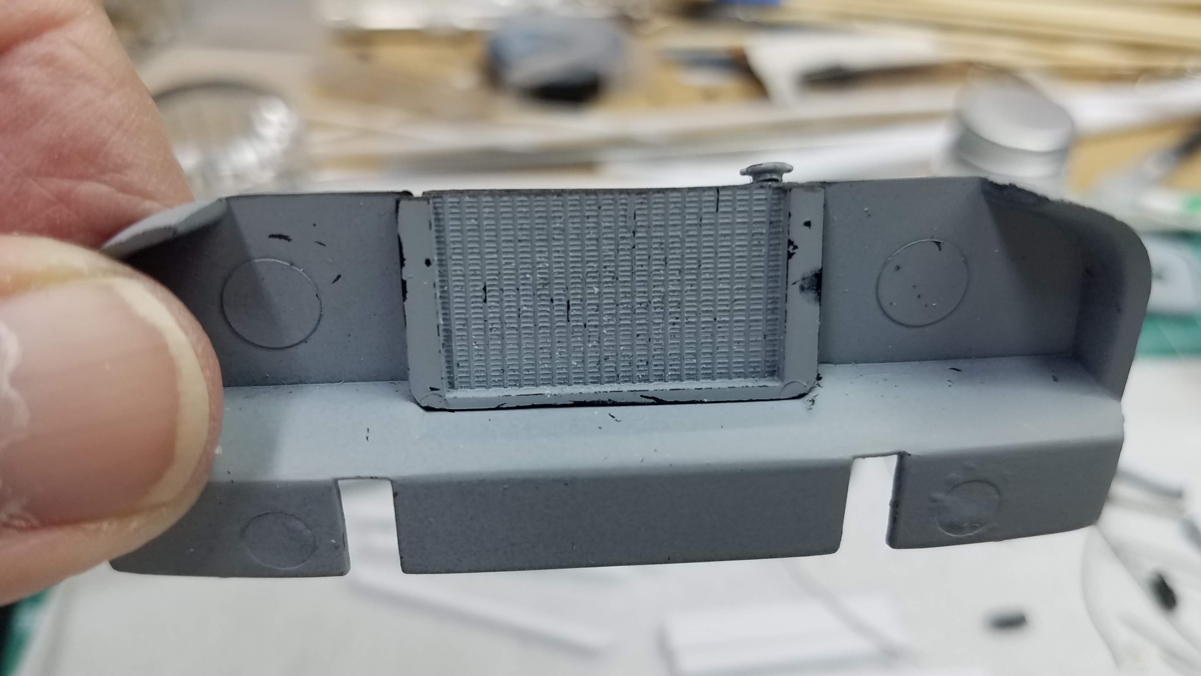
I decided to use the radiator that came with the kit, after all, it already fits in the opening. But what to do with the tank? I searched the Internet and found nothing, except that I had never thought about using a cross-flow radiator that has it's tanks on the sides. I roughed out a simple model and it will work! So... I cut the radiator the height of the opening. I then measured the tank of the original radiator and found that 0.100"/2.54mm square rod would be perfect. I cut two pieces the length of the radiator and glued them in place. I then cut the radiator cap from the original radiator and used that on my version. The last thing I did was use a #53 (0.059") drill and drilled the tanks to accept the radiator hoses.
54 of 92
It fit perfectly in the opening and by placing it on the front side of the body, the fan cleared and the grill still mounted nicely in it's place.
55 of 92
This is the radiator from the back side, the engine bay side.
56 of 92
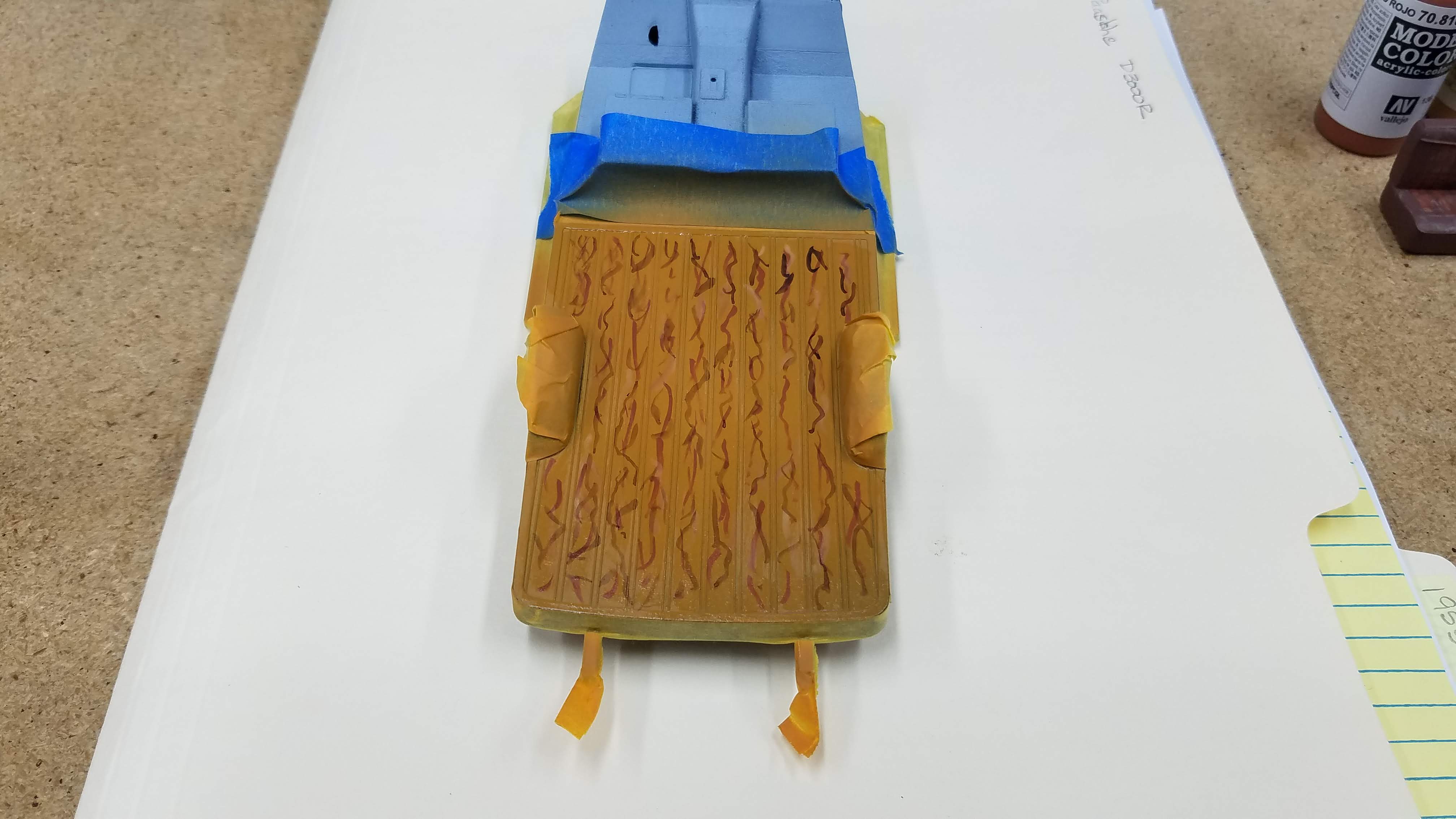
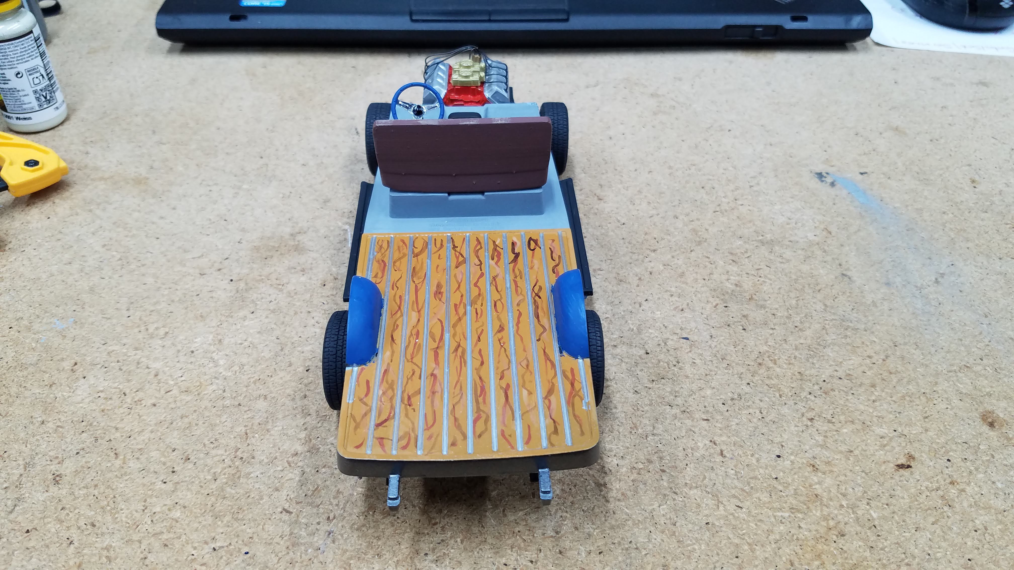
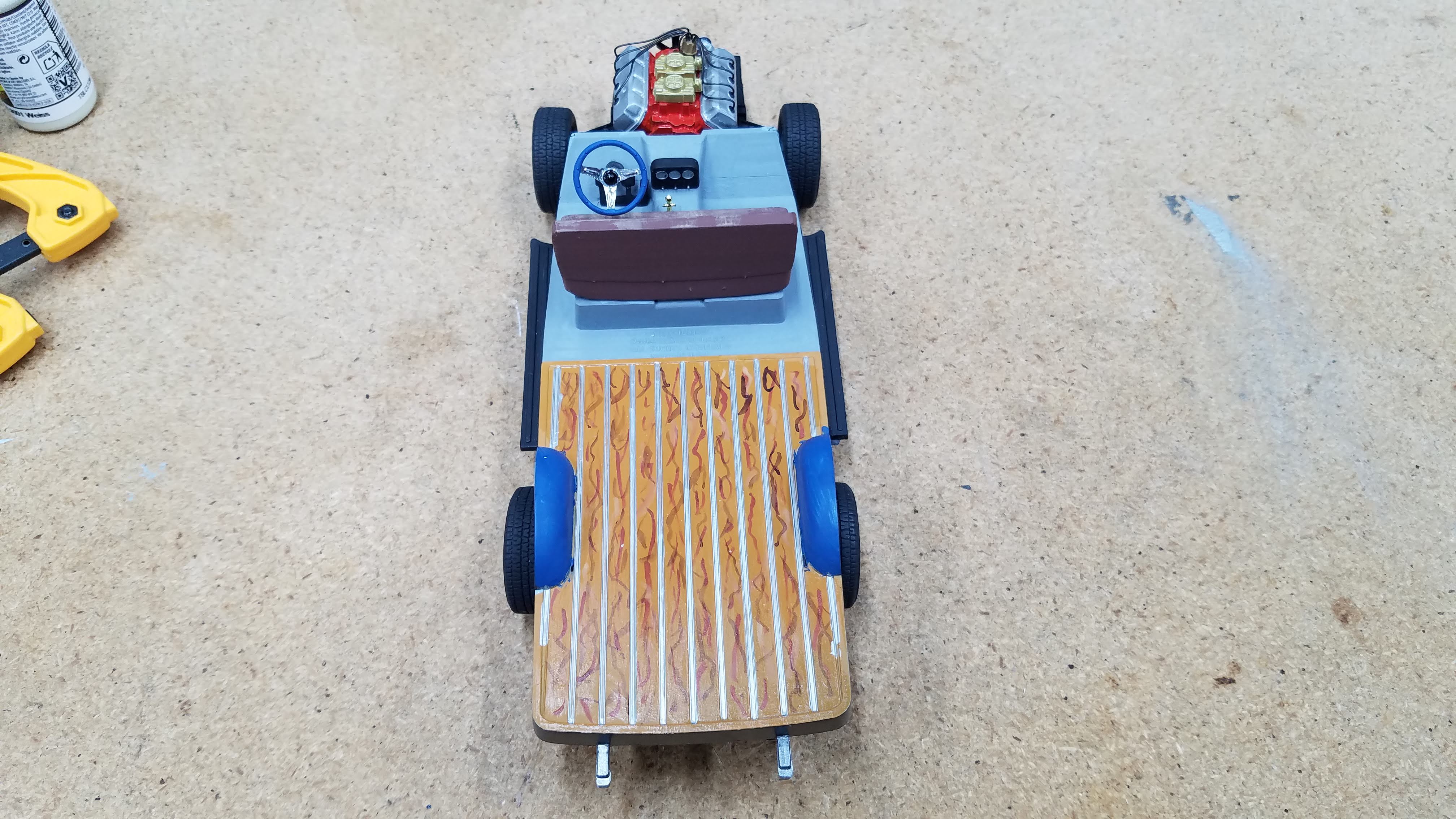
In the next several photos I made my first attempt at painting wood grain. I don't like the way I did it, it looks 'cheesy', even after clear coating it. I attempted to follow the Vallejo Step by Step for Wood Imitation, but I did not do a very good job. I started by painting the entire bed with Vallejo 71.077 Wood, then I used the following for the grain:
- Vallejo 70.818 Red Leather
- Vallejo 71.348 USAF Tan
- Vallejo 71.042 Dark Brown
57 of 92
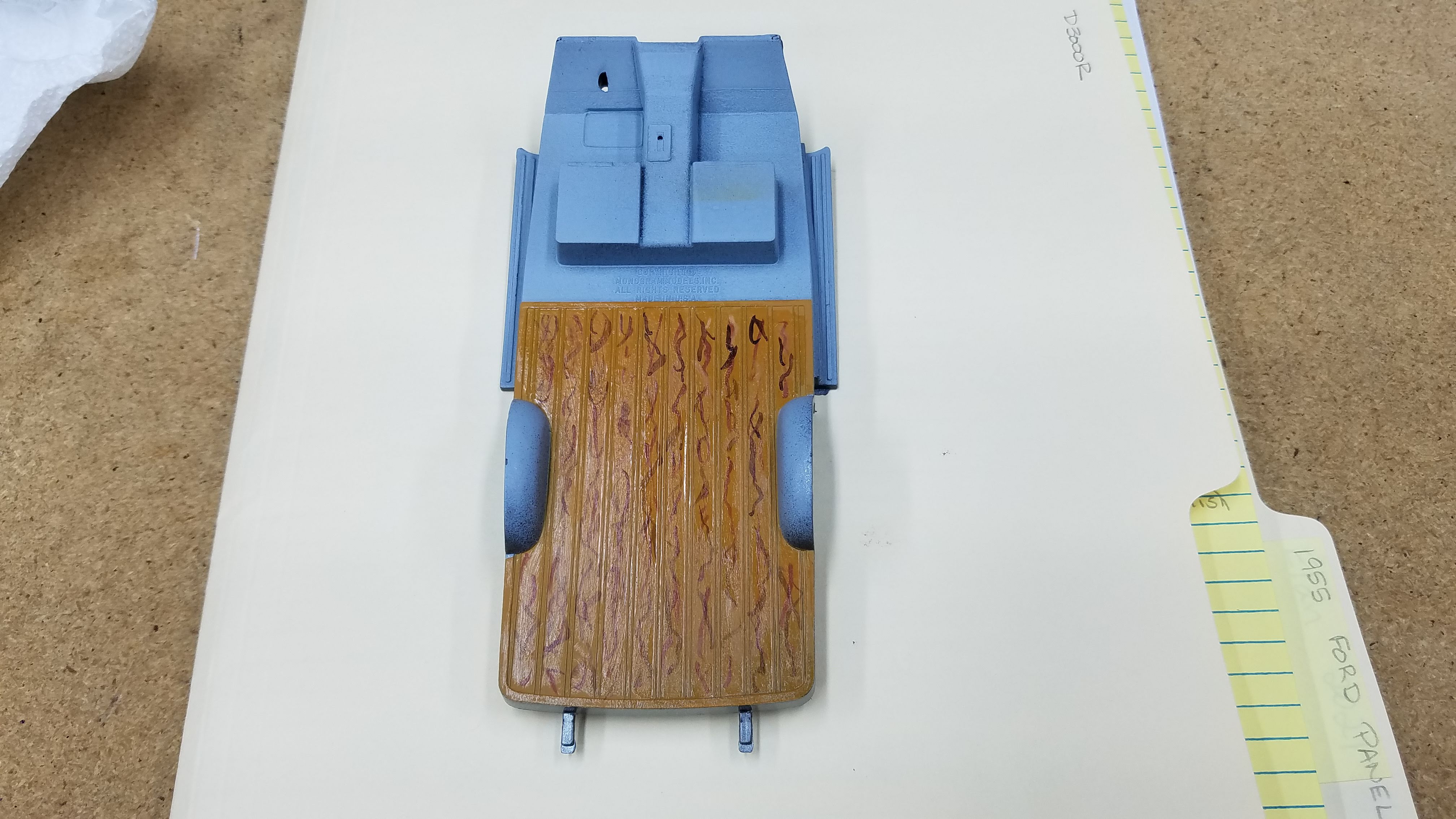
Truck bed with the masking tape removed.
58 of 92
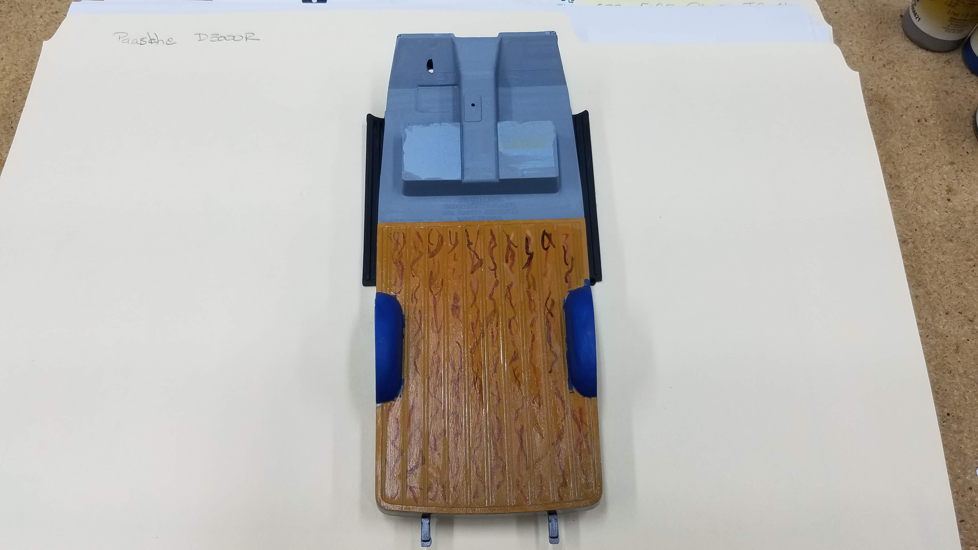
The interior with the fender wells painted the body color, the cab carpet painted with Vallejo 71.277 Dark Gull Gray and the running board painted with Tamyia XF-85 Rubber Black.
59 of 92
I wanted try my hand at painting a worn weathered leather seat. I followed the Vallejo Step by Step Painting Leather Seats. Again...as can be seen here, I did not do a very good job. I'm still a novice at dry brushing and blending colors, but I'll get there.
60 of 92
The interior tub is finished. The seat is mounted. The pedals and steering column are painted with Tamiya XF-1 Flat Black. The Steering wheel is in the body color; Vallejo 71.266 Dark Blue RLM24. The steering wheel spokes were done with a Molotow Chrome Pen and the center hub of the wheel is Tamiya X-1 Gloss Black.
61 of 92
The interior tub looking from the back of the van. I used the gold shifter that came with the kit.
62 of 92
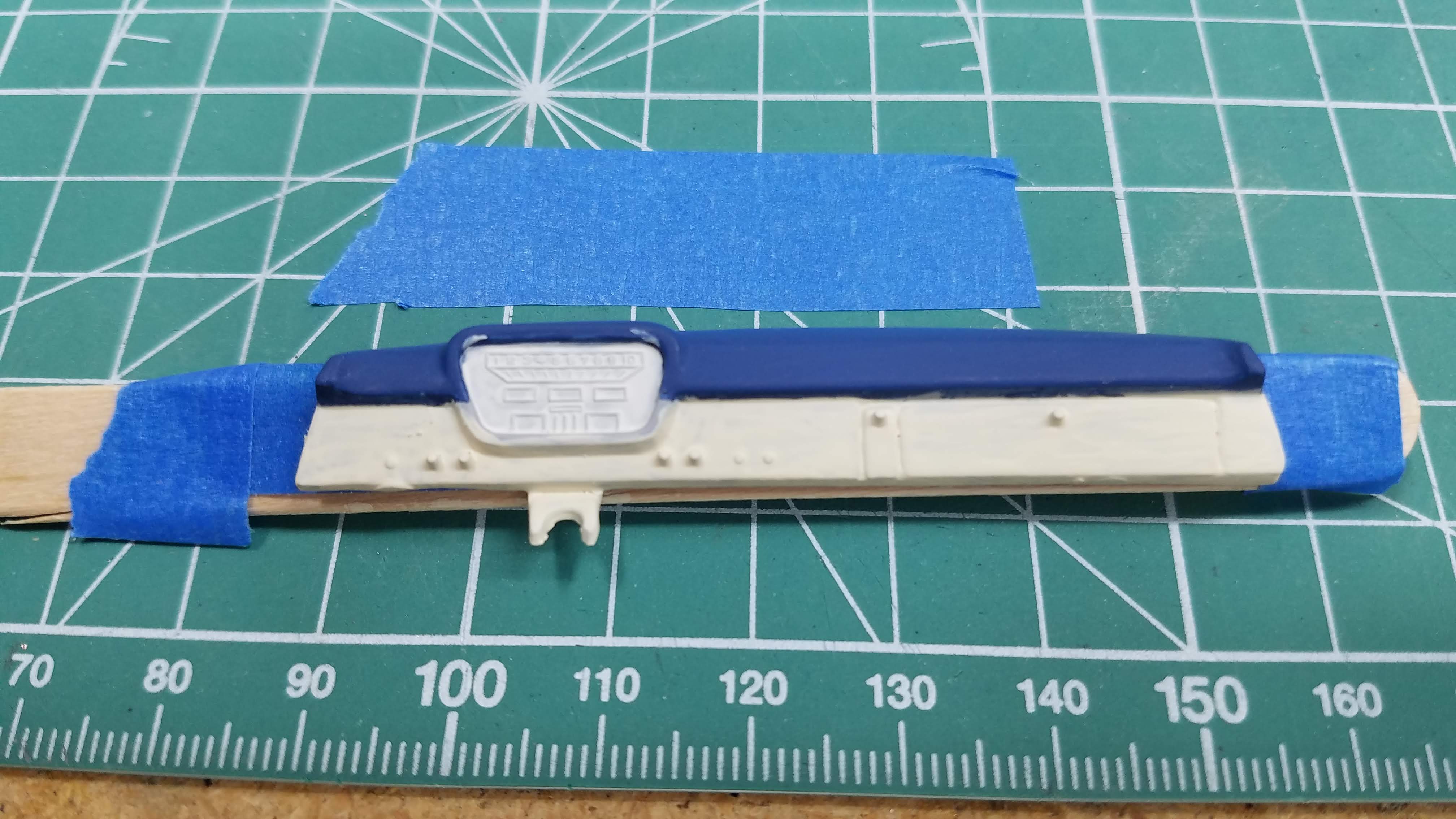
The dash board is painted. The top half of the dash is the body color; Vallejo 71.266 Dark Blue RLM24. The bottom half of the dash is Vallejo 71.119 White Gray, and the background of the instrument cluster is Vallejo 71.279 Insignia White.
63 of 92
I used a black Sharpie to highlight the dash board knobs and I attempted to pick up some of the detail in the instrument cluster with the same Sharpie. Not good. Lesson learned, I should have found a decal of gauges. I than used a Molotow Chrome pen to outline the instrument cluster.
64 of 92
The next several pictures are the interior tub setting on the frame, left side.
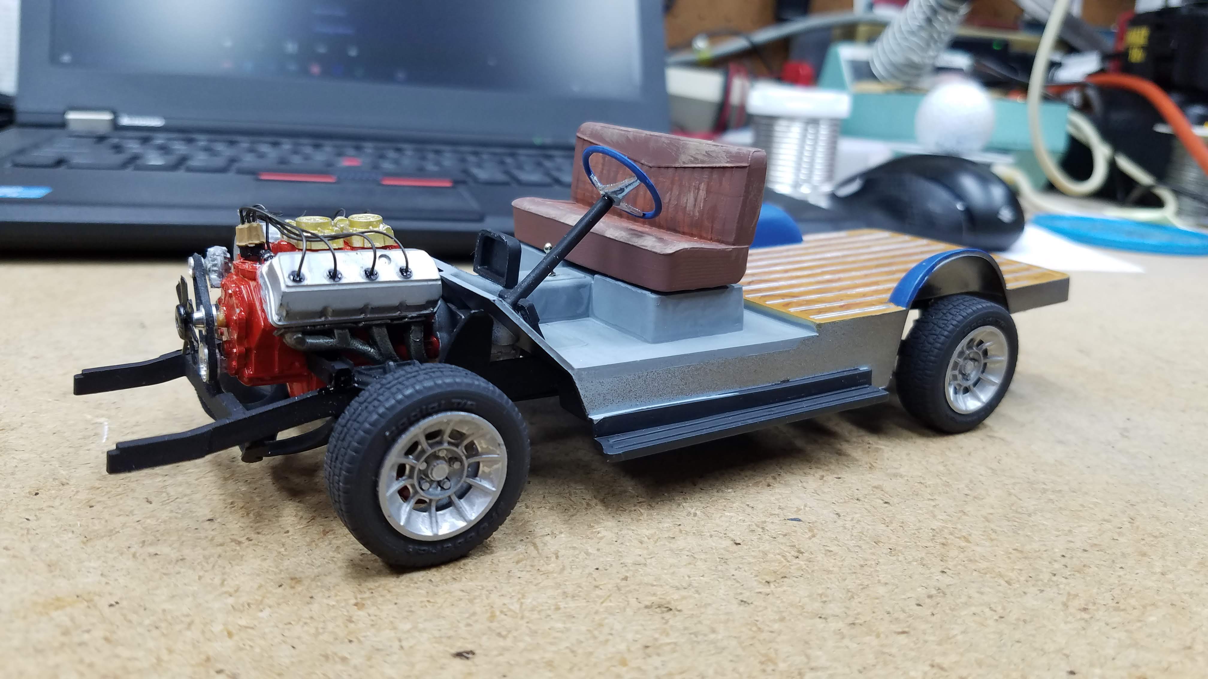
65 of 92
Interior tub setting on the frame, right side.
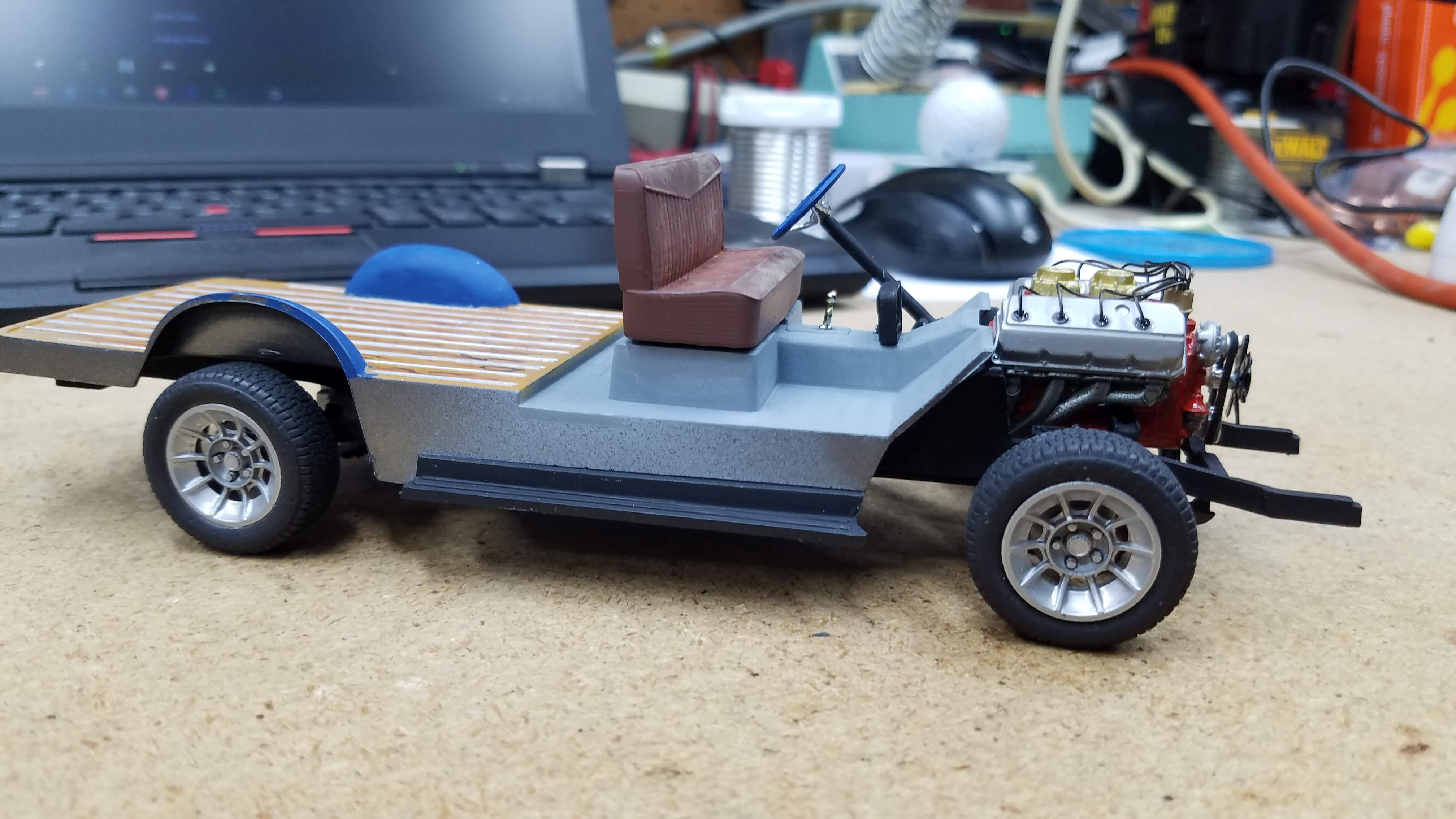
66 of 92
Interior tub setting on the frame, from the front.
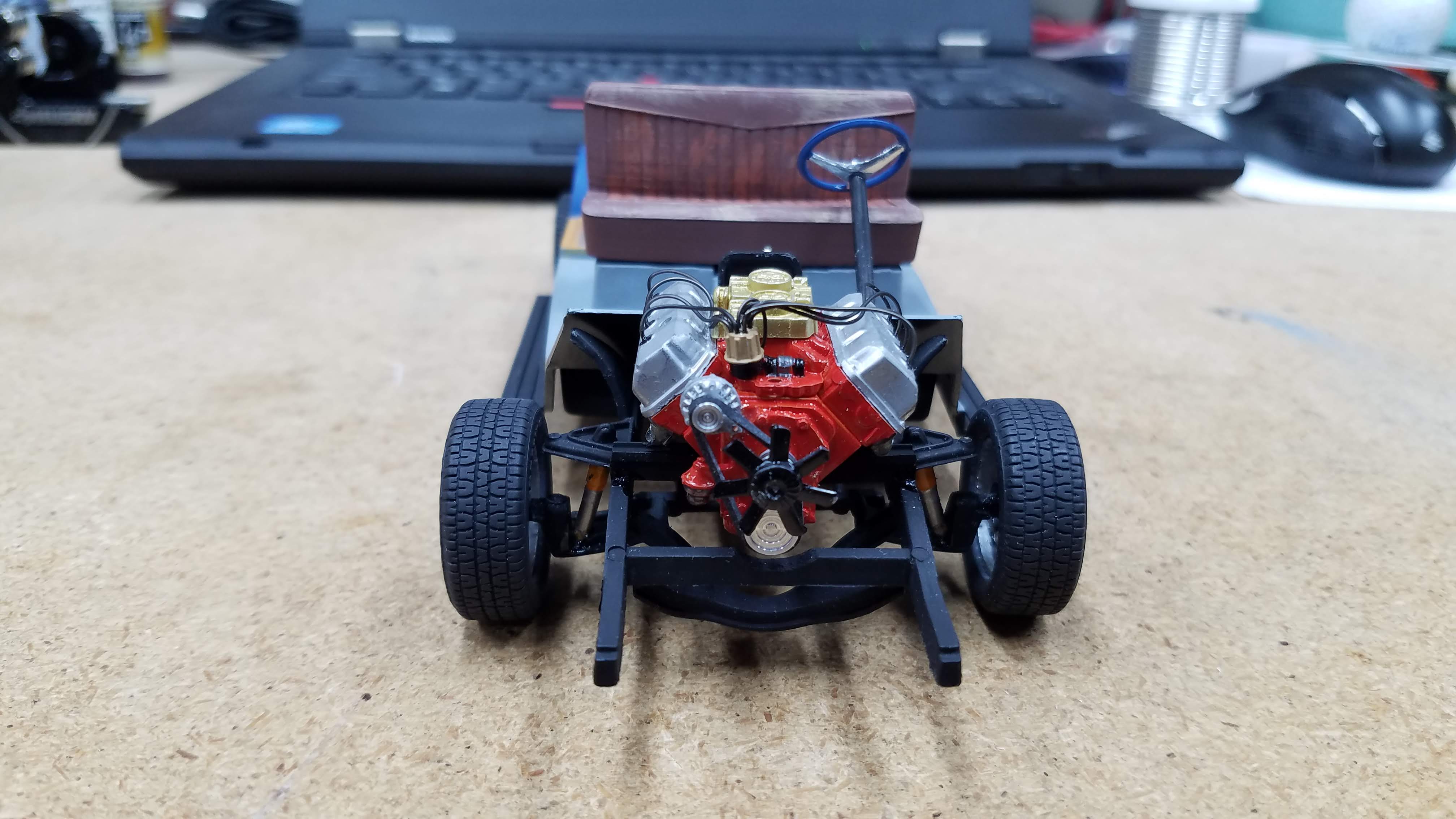
67 of 92
Interior tub setting on the frame, from the back.
68 of 92
Interior tub looking down from the top so that the center instrument cluster can be seen.
69 of 92
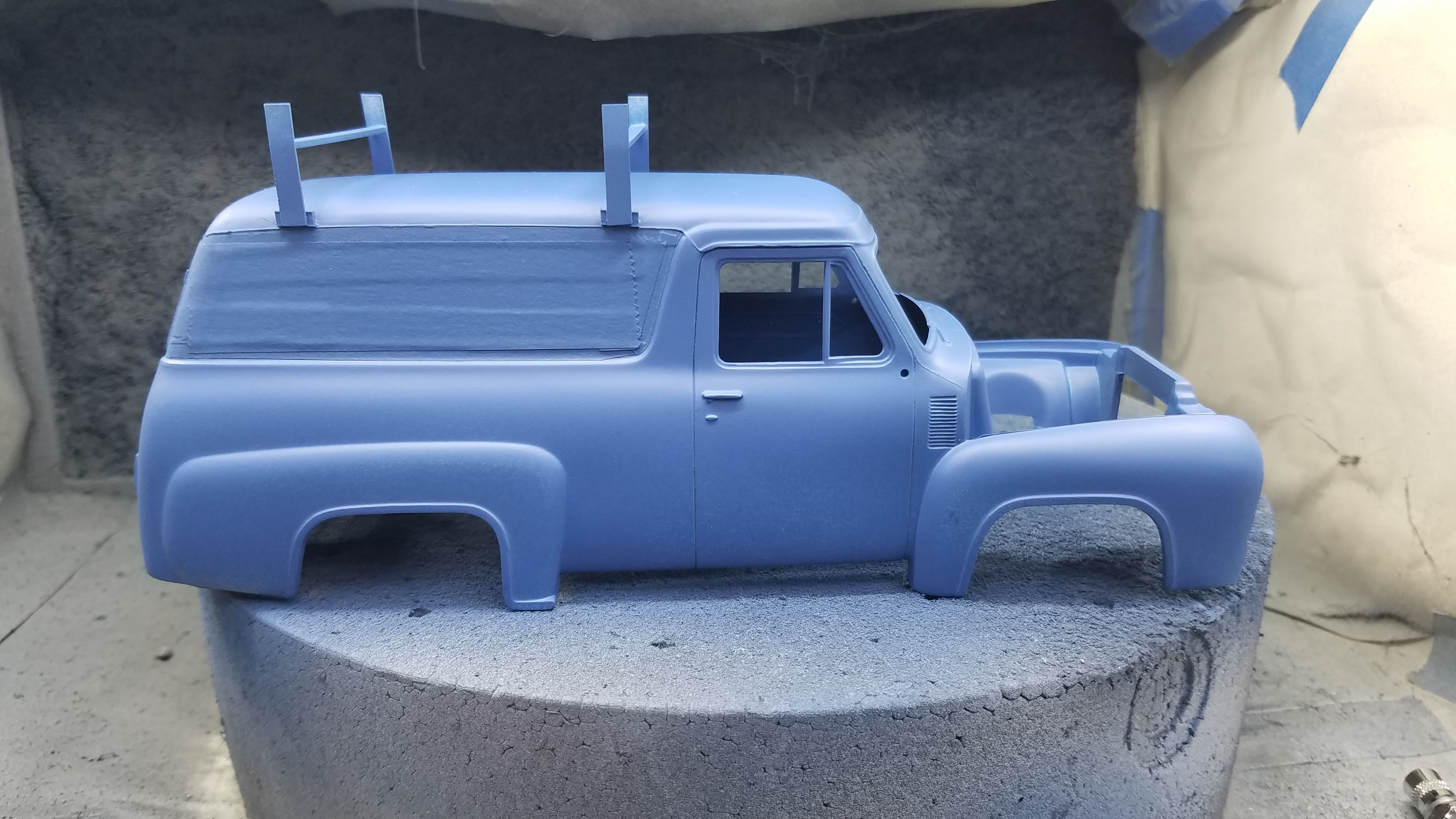
The body was primed and is masked to paint the side panels.
70 of 92
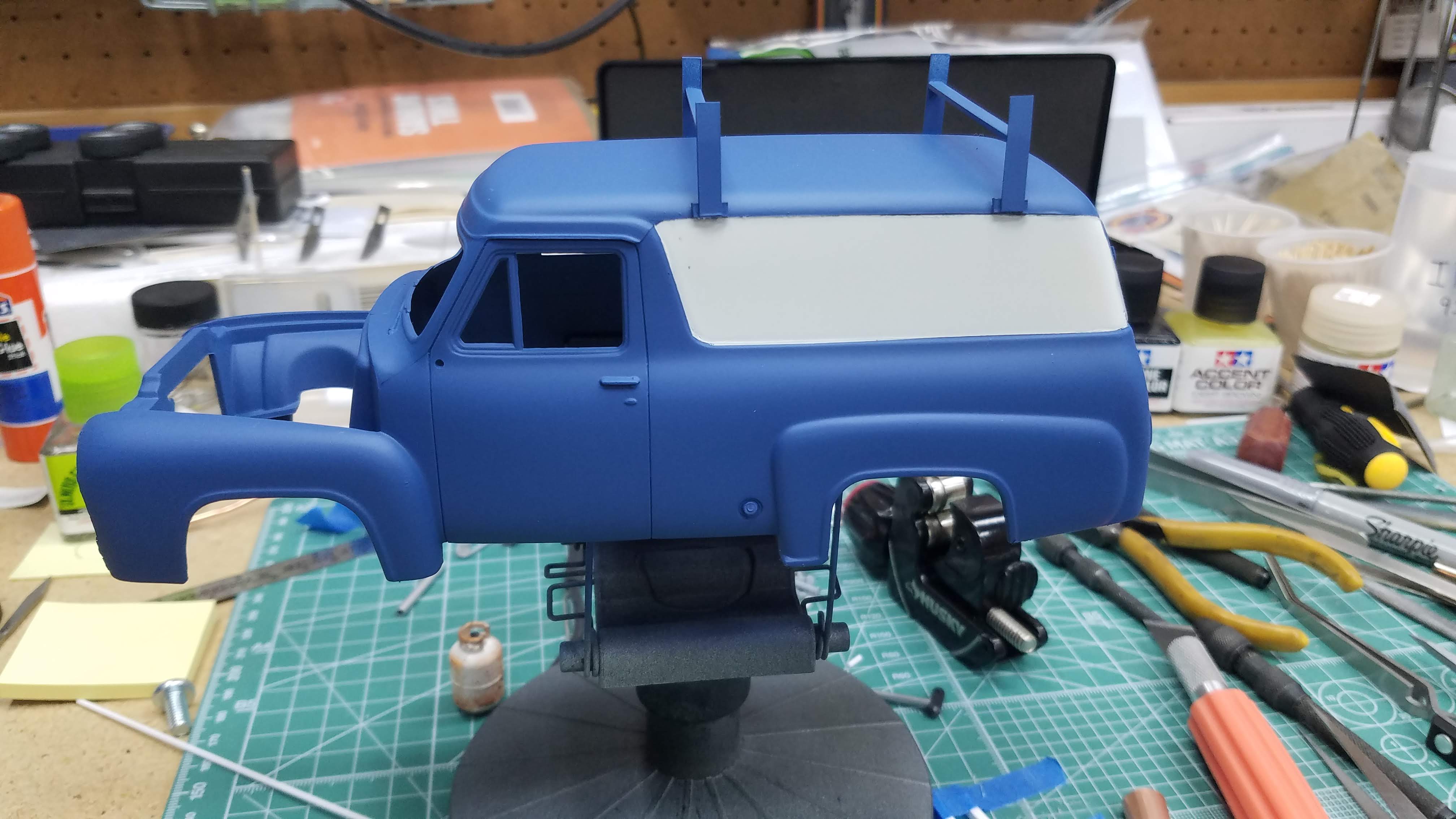
The mask is removed showing the painted side panels.
71 of 92
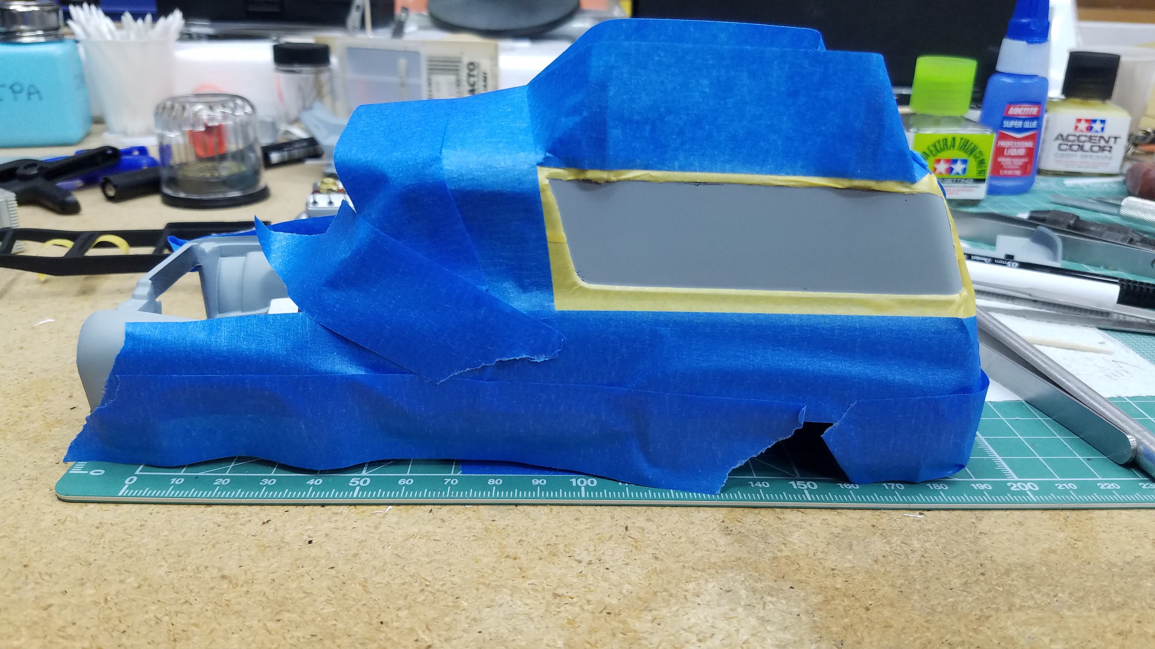
The side panels paint was allowed to cure for more than 48-hours. It was than masked so the body could be painted.
72 of 92
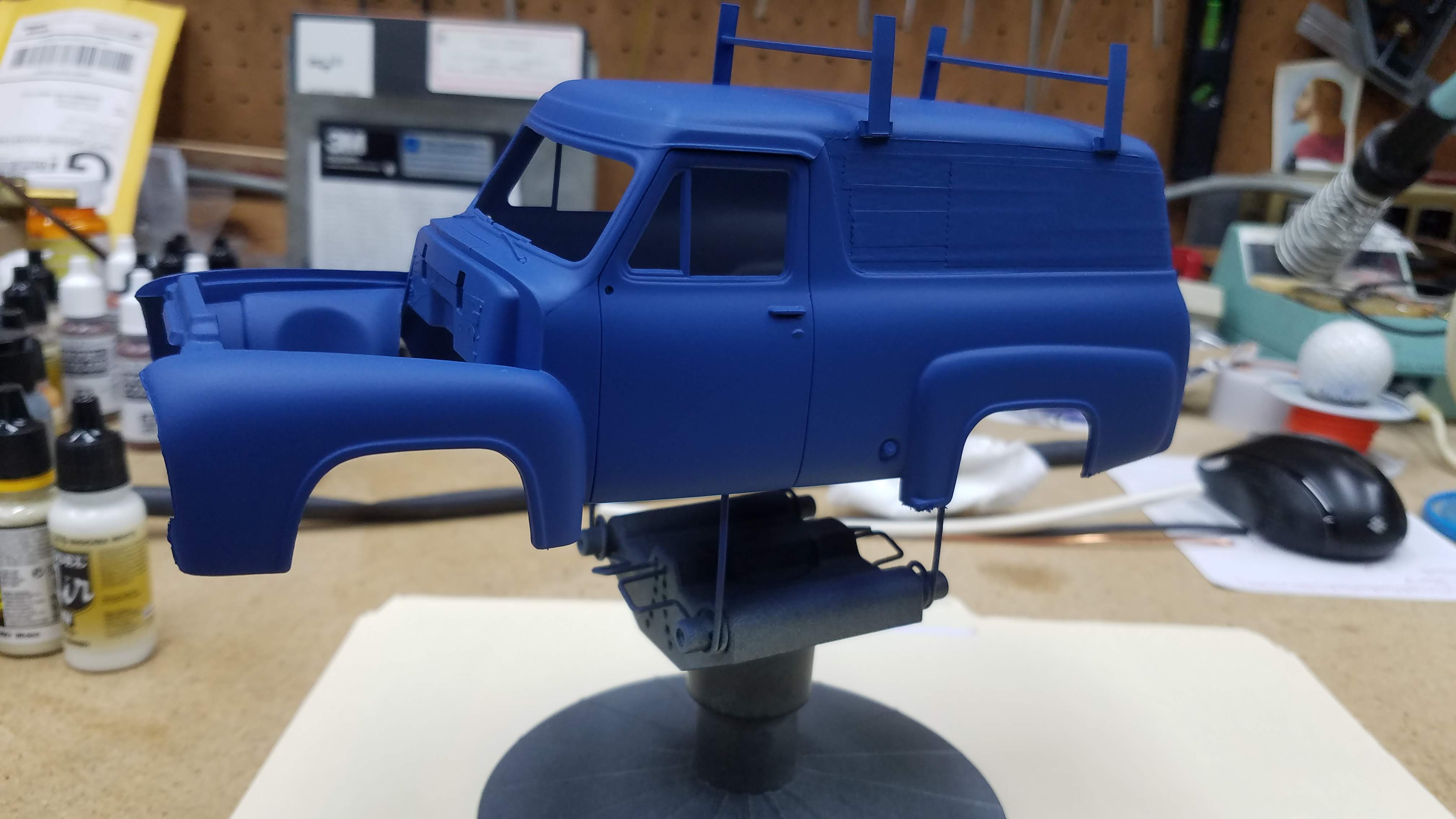
The first coat of body color, Vallejo 71.266 Dark Blue RLM24. In this photo, the LED lighting in my spray booth is making the dark blue look a lot lighter than it really is. (I actually like that shade of blue. I'll have to try and duplicate it for later build.)
73 of 92
The second and third coat of Vallejo 71.266 Dark Blue RLM24 was applied and on the holder waiting to fully dry. This photo is a better depiction of the actual body color.
74 of 92
The side panel masking was removed.
75 of 92
More masking is applied to paint the roof racks and the door handles. The roof racks were brush painted with Vallejo 71.279 Insignia White. It took four coats to cover the body color. The door handles, windshield wipers and gas cap were painted with a Molotow chrome pen.
76 of 92
All the masking tape was removed.
77 of 92
The front of the body with the radiator were installed.
78 of 92
A look from the roof at the engine compartment showing the radiator and it's silver radiator cap.
79 of 92
Two coats of Vallejo 70.510 Gloss Varnish was applied but got a-bit 'crinkly'. I think I had my airbrush pressure to low and I should have used some flow retarder. Oh well, I think it still look good.
The next several photos are of the completed build.
80 of 92
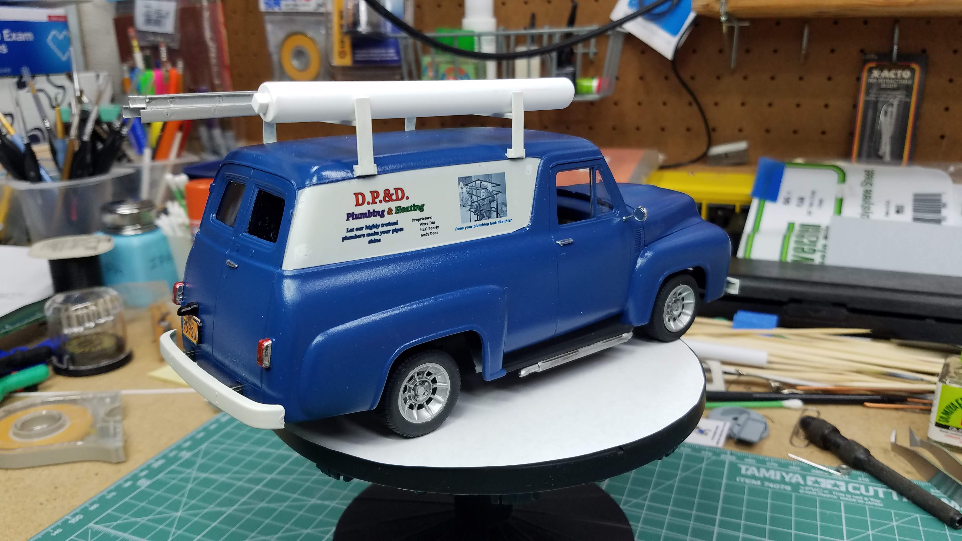
Completed Build
81 of 92
Completed Build
82 of 92
Completed Build
83 of 92
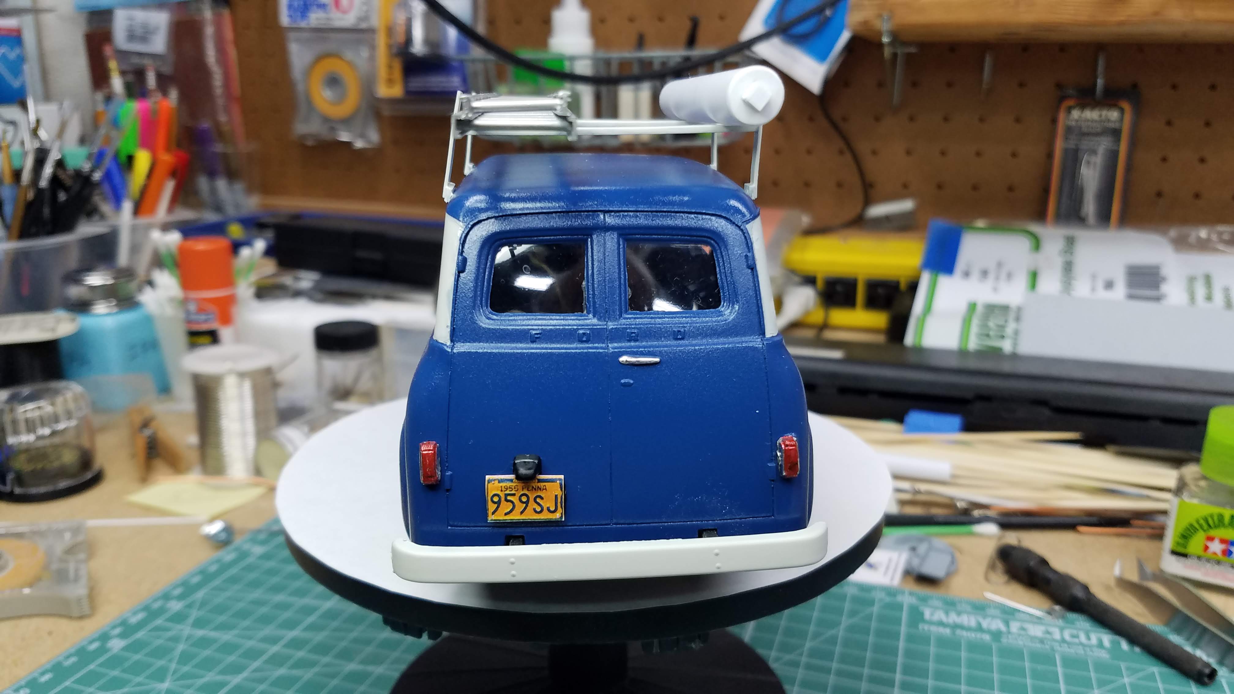
Completed Build. I make my own license plates. Since I live in Pennsylvania, I want to use a PA license plate. I found a 1955 Pennsylvania plate on line and using Gimp GNU Photo Editor I increase the resolution and sized it to fit the license plate holder. I print them on plain paper and use Elmers Disappearing Purple School Glue to glue them in place. After two years, the ones I previously did are still solidly attached.
I did the tail lights with a Molotow chrome pen and then painted the lenses with Model Master Clear Red.
84 of 92
Completed Build
85 of 92
Completed Build
86 of 92
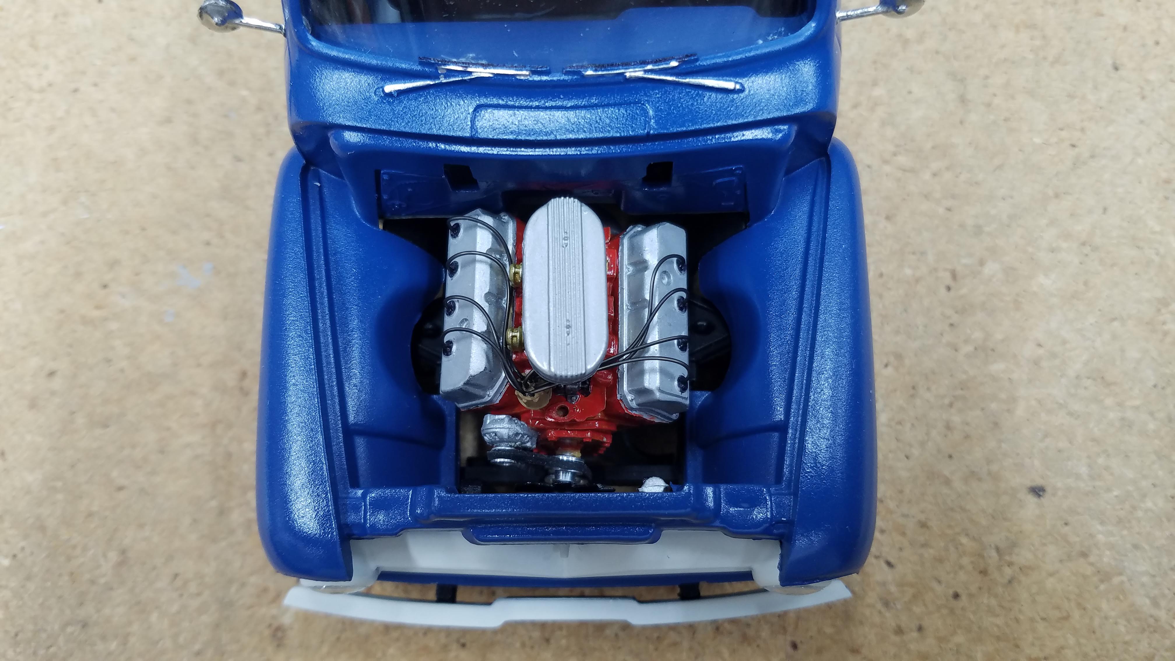
This picture is with the hood open and looking at the engine.
87 of 92
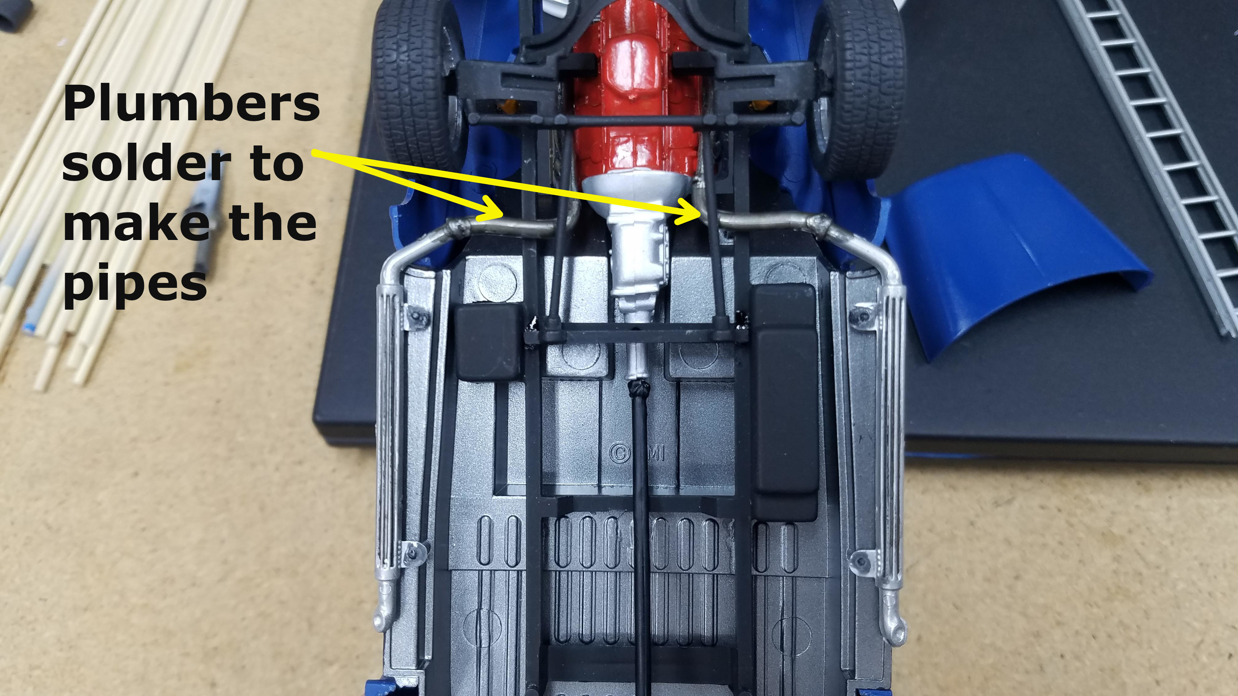
I wanted to use the side pipes. In order to use them, the Hemi exhaust manifold pipes were too long. I cut the Hemi exhaust manifold pipes and then fabricated connecting pipes using plumbers solder. I then painted the solder with Vallejo Metal Color 77.723 Exhaust Manifold making it thinner at the joints so that it would fade into the other pipes looking like there was a connection made.
88 of 92
I made my own decal using Gimp GNU Photo Editor. I found the picture of Curly in the mass of pipes from the stooge short "A Plumbing We Shall Go". Before I use any photo's I make sure they are in in the Creative Commons area so I don't get nailed with a copyright violation. I then use Gimp and create an image the size I want the decal and add text and any photos. When they are finished I print them on water slide paper in my color laser printer.
89 of 92
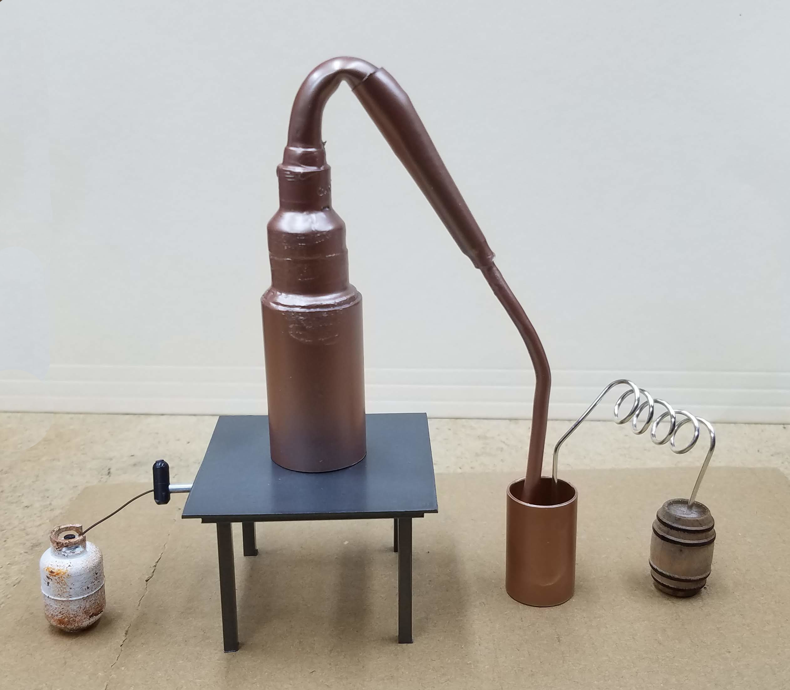
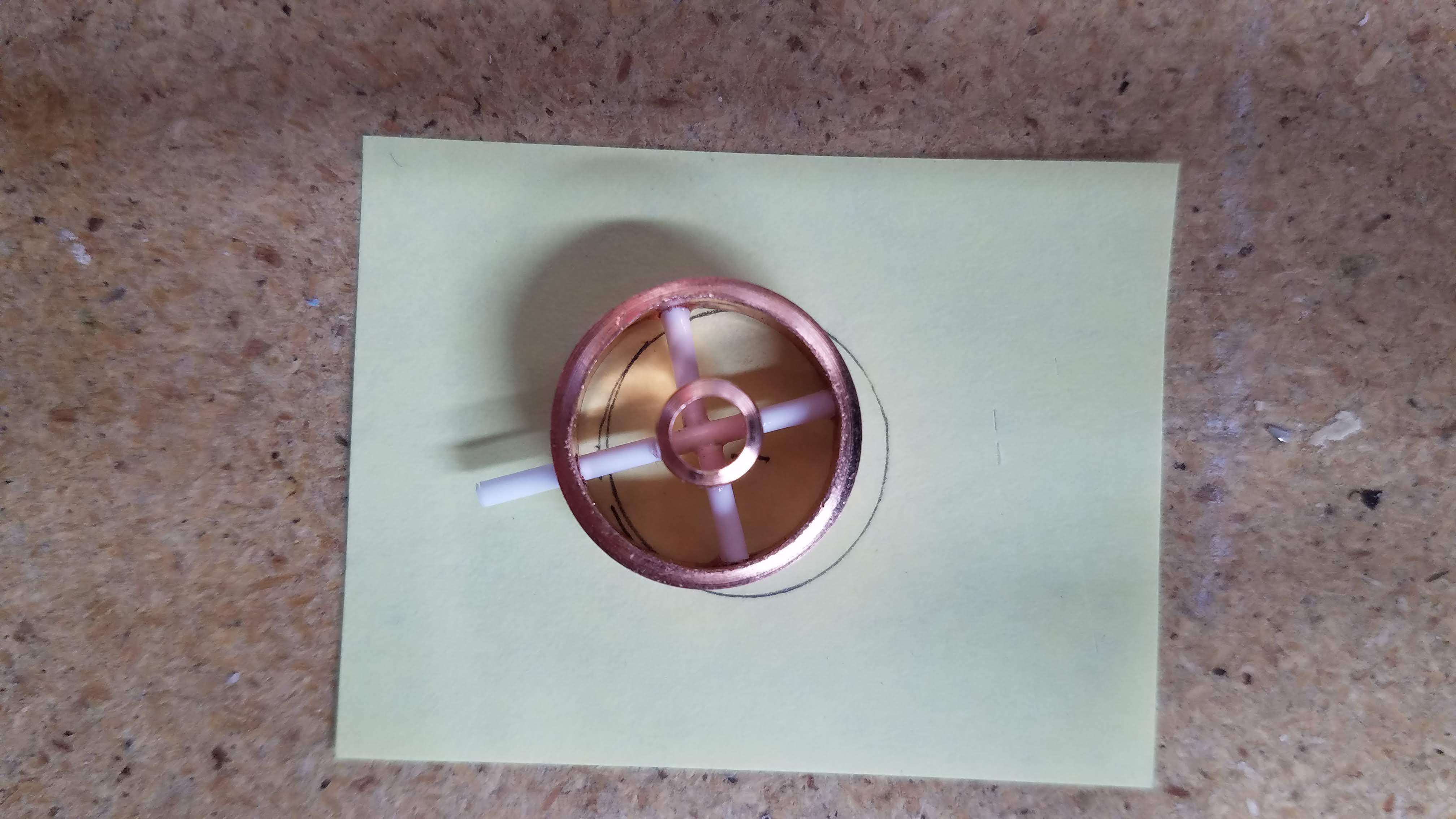
The main business is actually building moonshine stills, so I thought I would build a 1:24 scale 10-gallon copper still with a thump barrel and a chared white oak barrel.
The following photos are of this still and it's various parts.
90 of 92
This will be the burner to heat the still.
91 of 92
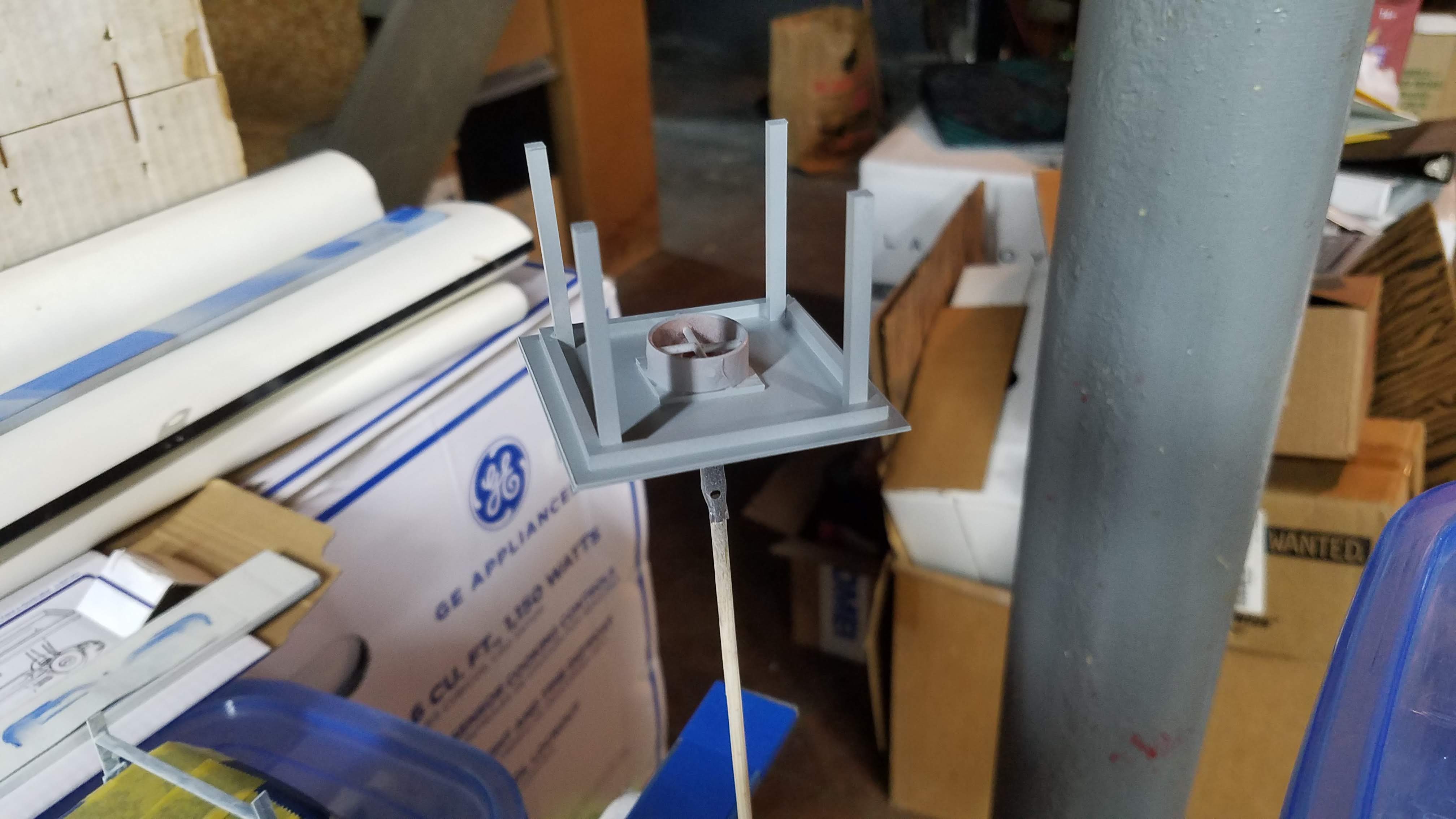
A scratch built table with the burner mounted on the bottom.
92 of 92
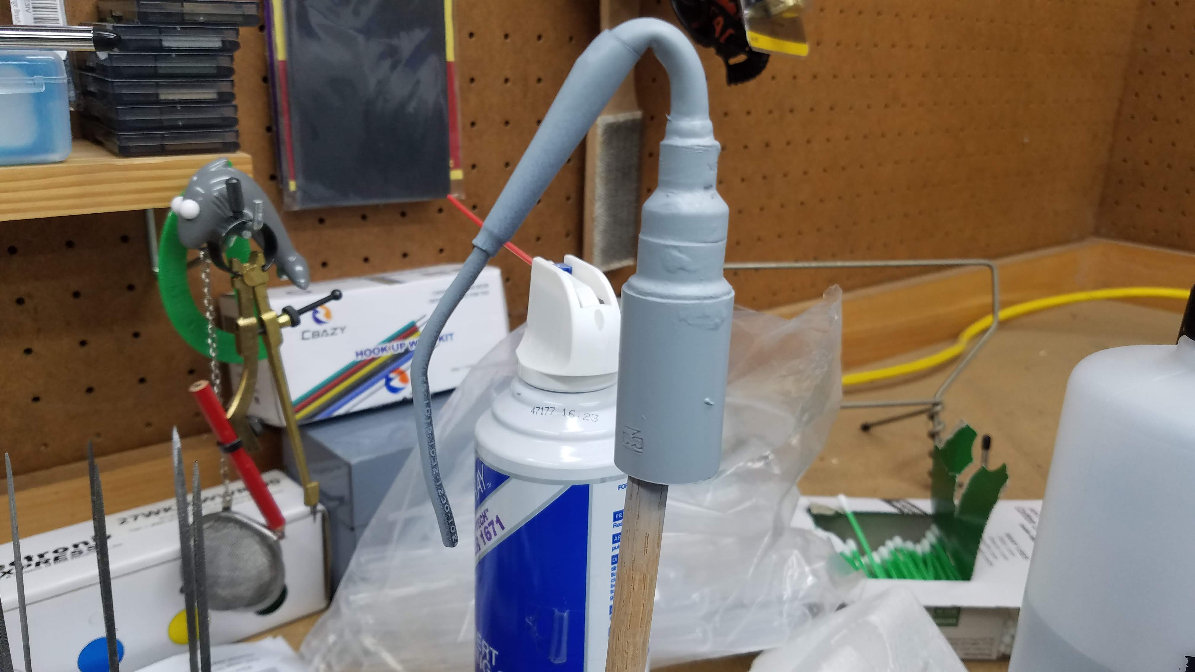
The still and thump barrel were sprayed with Vallejo Metal Color 77.710 Copper. The table was painted with Vallejo Metal Color 77.712 Steel. A piece of 0.125"/3.175mm aluminum tube was used to make a gas line to the burner. The gas regulator is just a piece of sprue and the hose going to the propane tank is a piece of 30 AWG (American Wire Gauge) wire that I use for spark plug wires. I bought the propane tank from Etsy The still and thump barrel are made from copper pipe adapters. The curved output pipe is made from a piece of TV cable on the top and 12 AWG electrical wire for the bottom that goes into the thump barrel. The tapered portion is shrink sleeving. The condensation coil is made with 18 AWG solid wire and I didn't paint it because I wanted it to be stainless steel. The wooden barrel was bought from Etsy - through Dollhouse Miniatures. The table was built from 0.040"/1.016mm sheet styrene. The bottom ridge was made from 0.100"/2.54mm square rod. And the legs were made with 0.125"/3.175mm square rod.