Opening
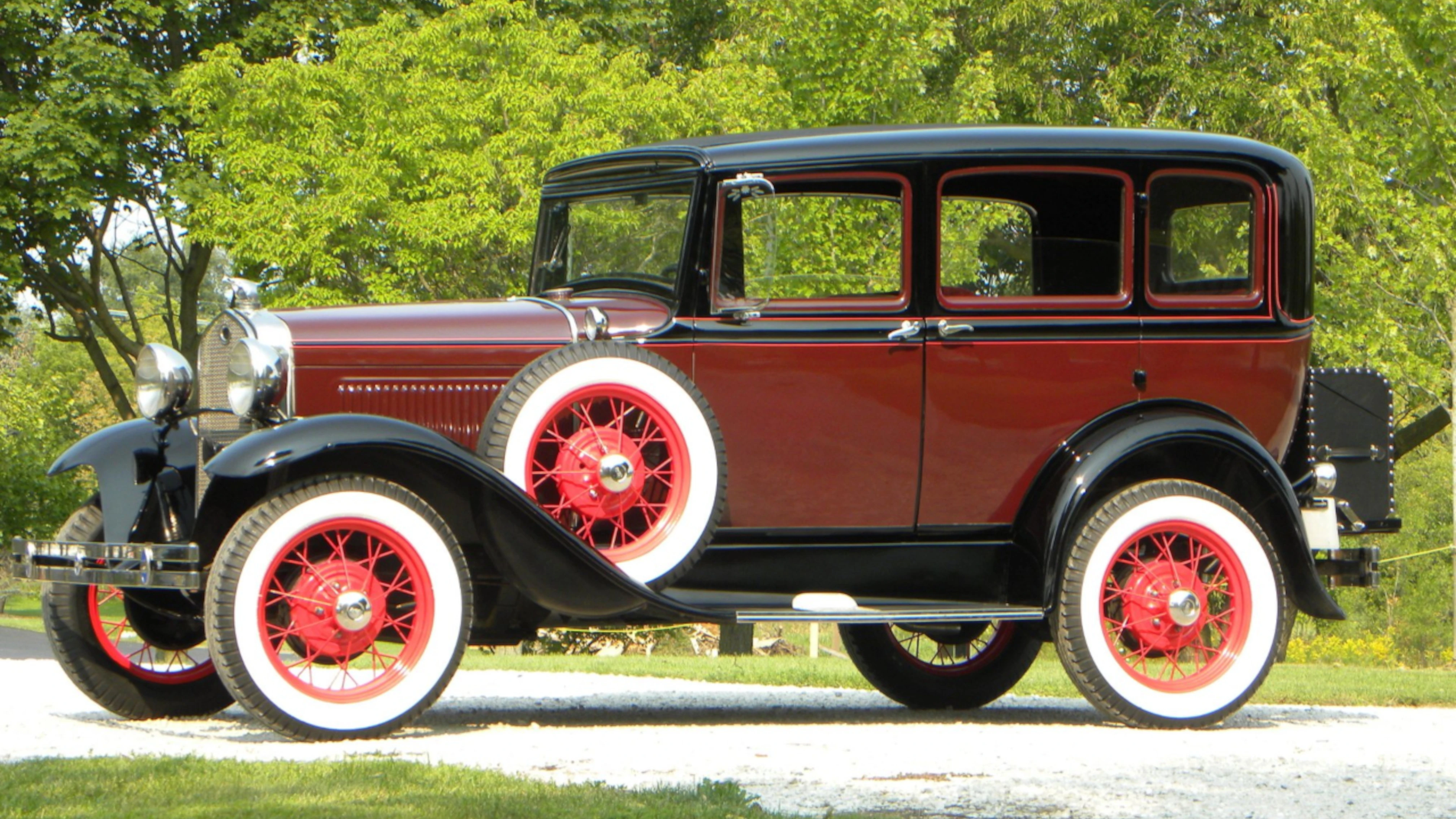
This is the look I'm shooting for. The die cast body does not have a lot of detail; therefore, I might not be able to do the masking around the windows and the strip along the side of the door where the door handles are mounted. This photo will be replaced with a photo of my finished model when the project is complete.
This is a 1931 Ford Model 'A'; however, the 1928 and 1931 are very similar. This picture came from ClassicCars.com I hope the owner of this picture does not mind that I used it.
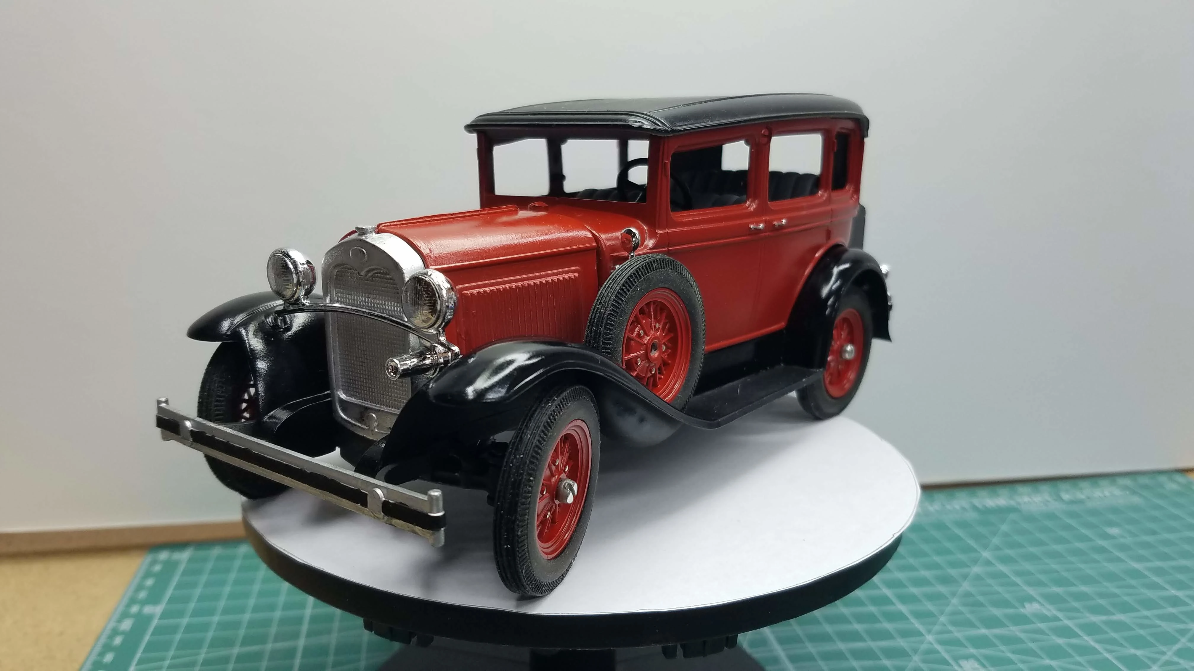
Here is a picture of my finished build. The only thing I did not do was the block trim along the doors and around the windows, the chrome around the hood, and the white walled tires. The model did not come with clear parts for windows.
1 of 50
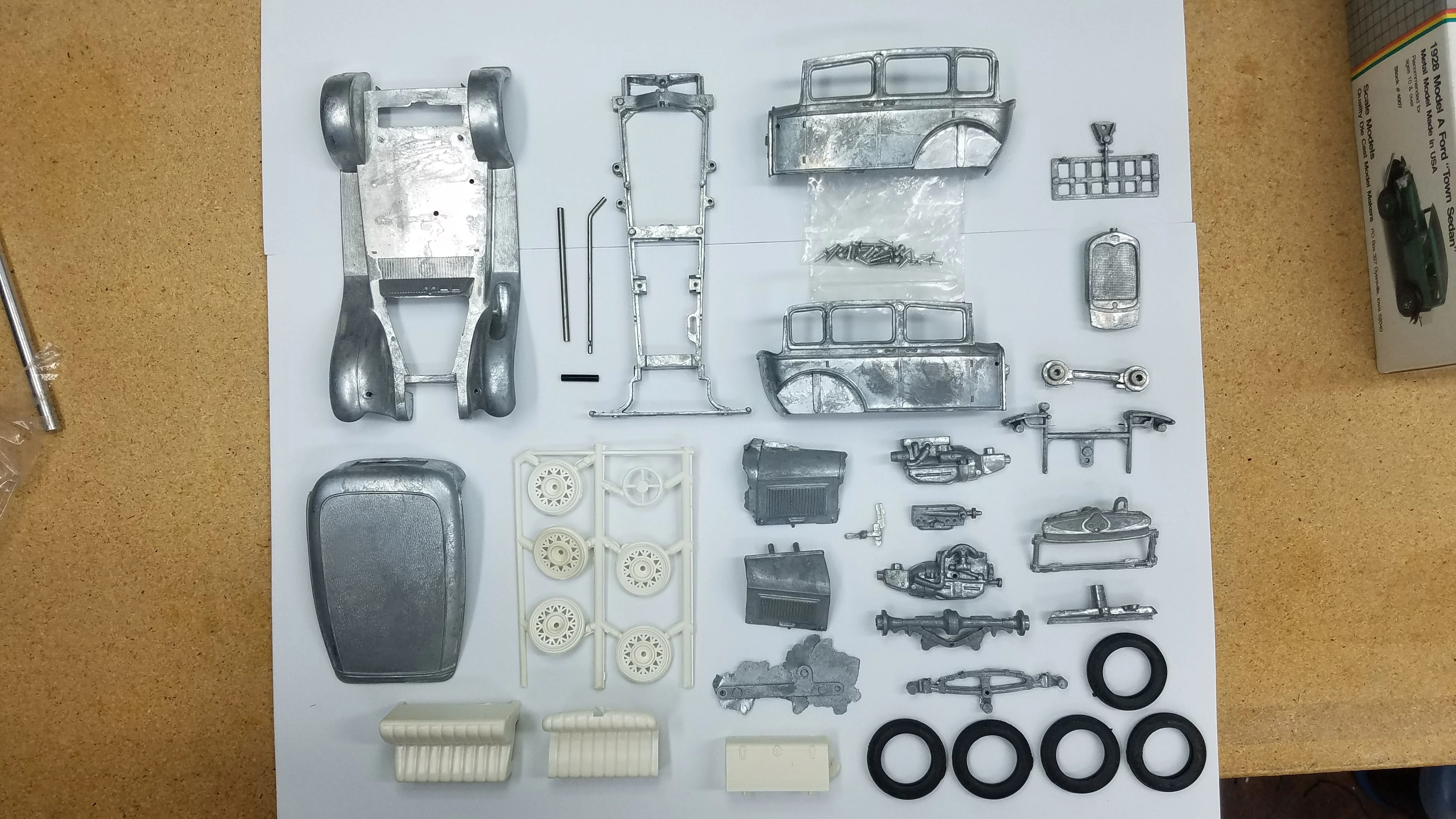
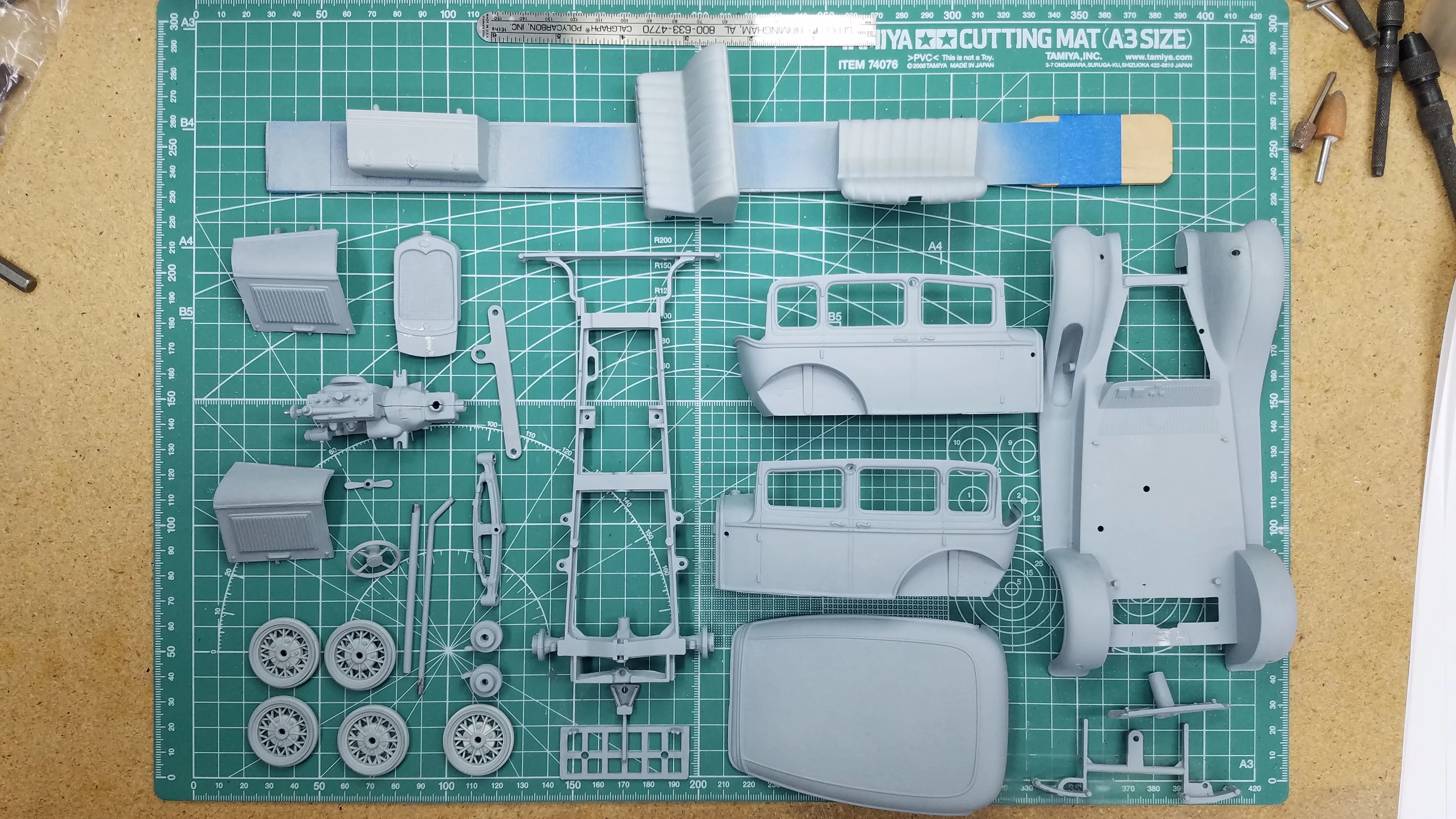
These are all the parts except the chrome tree. (The chrome tree was missing from this box even though the box was still wrapped in plastic wrap. It could be that it was re-wrapped before I bought it? I eventually opened the 1931 version of the kit and took the chrome tree from that kit.)
The box states that there are over 75 realistic pieces; however, even with the chrome tree there are less than 50 pieces.
2 of 50
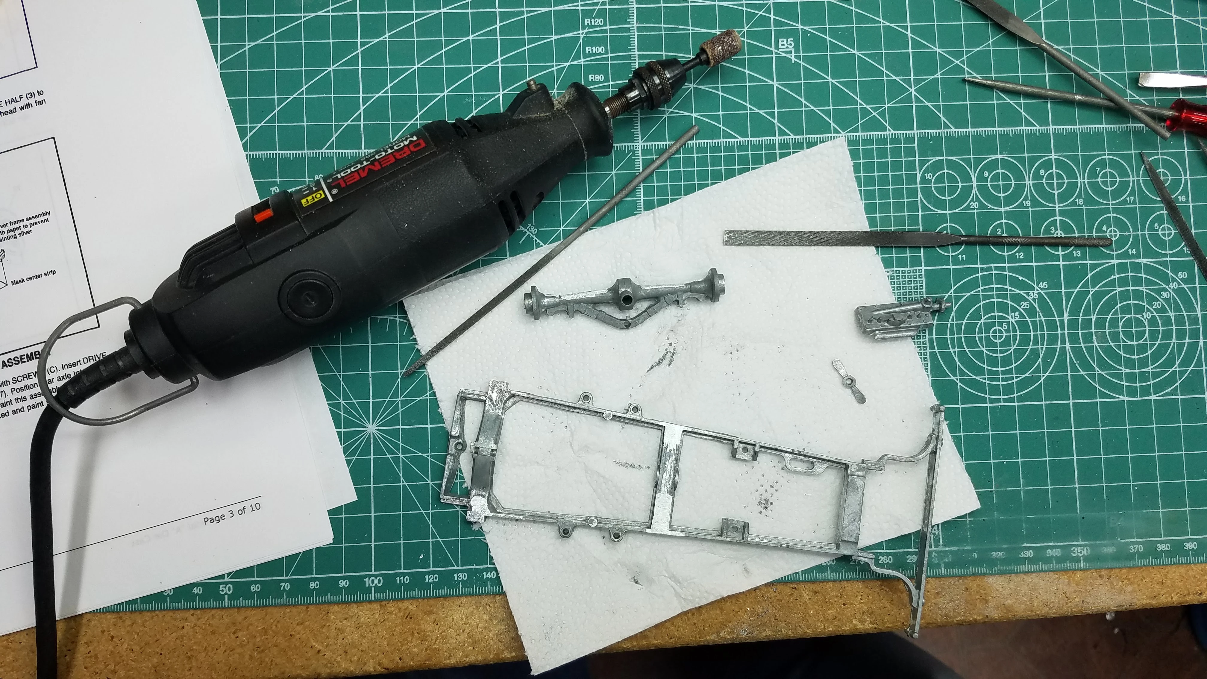
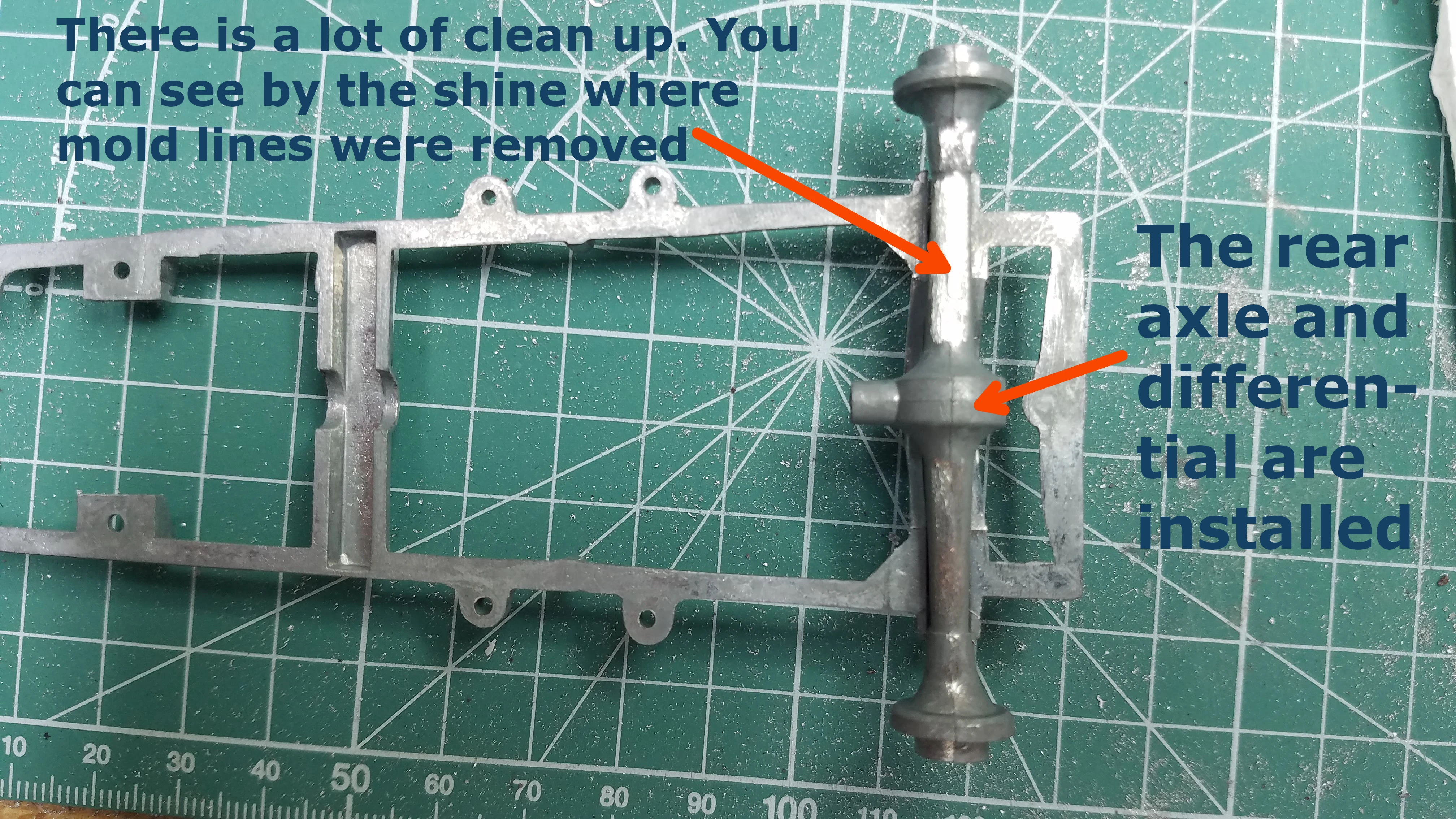
There is a lot of clean up to do on the cast parts. I started with the engine halves and moved to the frame. Using a hobby file set is ok for the small areas, but to get rid of the injection mold marks and larger pieces of flash my Dremel tool with a sanding drum is being used.
3 of 50
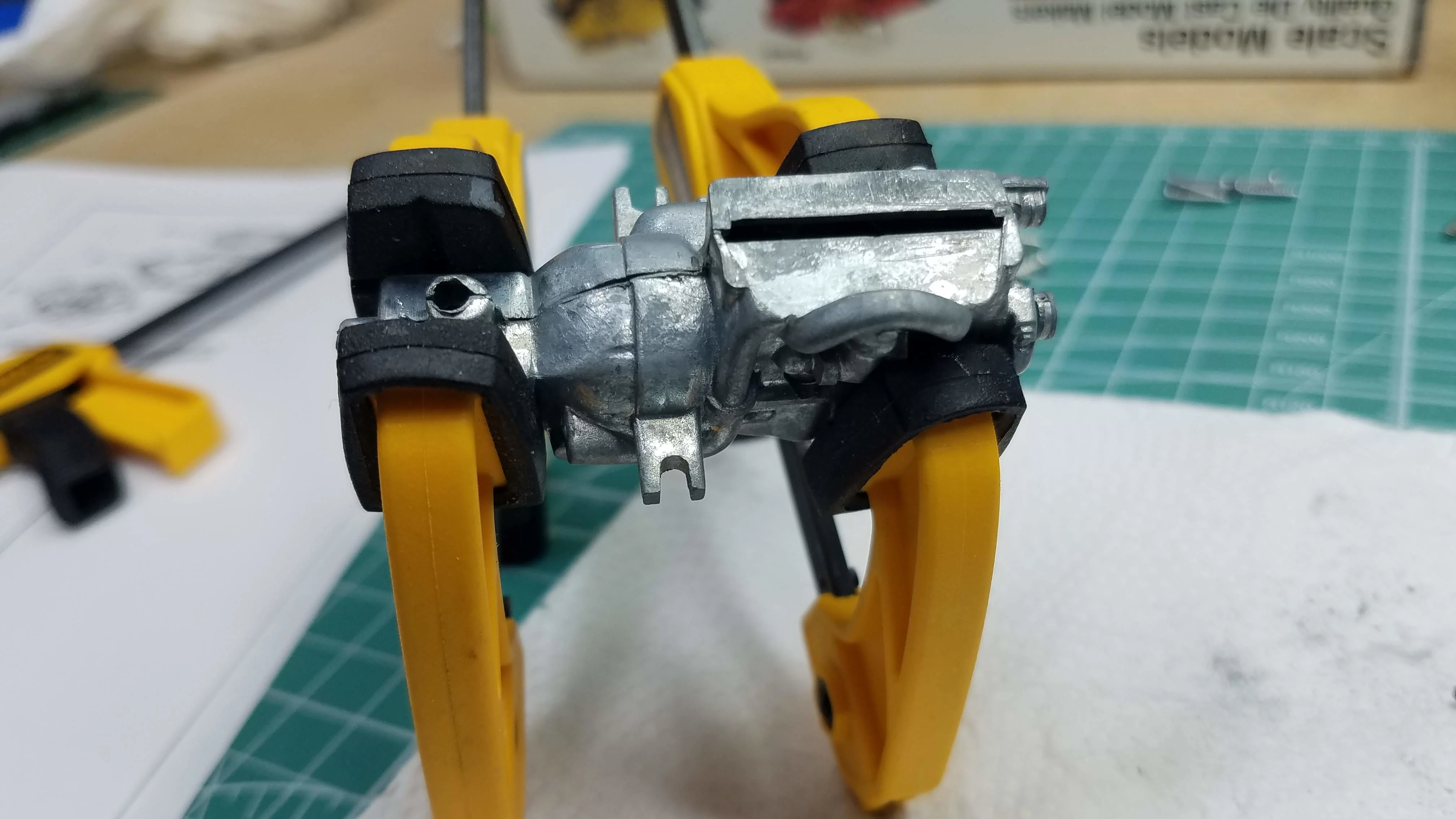
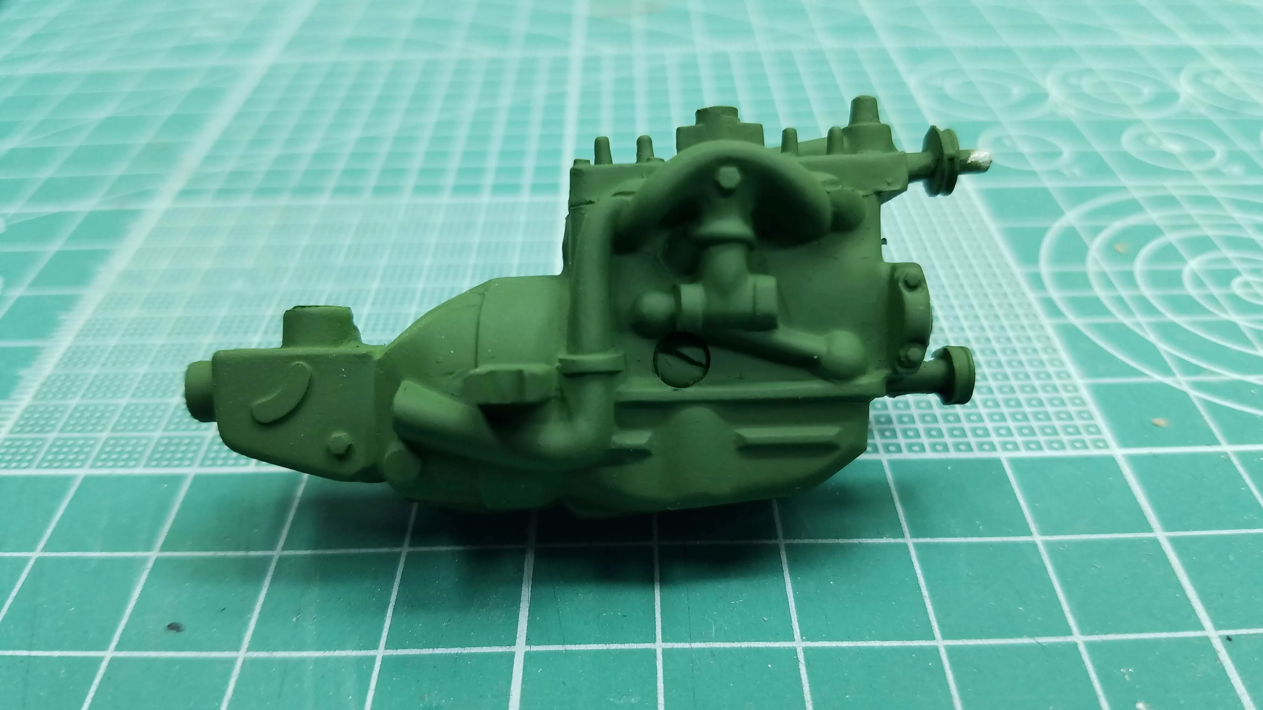
The engine halves are put together and the one screw that is supposed to hold them together was inserted. After the screw was screwed in and tightened the halves were still not fully closed, so I clamped the halves together and ran some Loctite along the seams. When the Loctite dries I'll use a file to smooth out the joint.
4 of 50
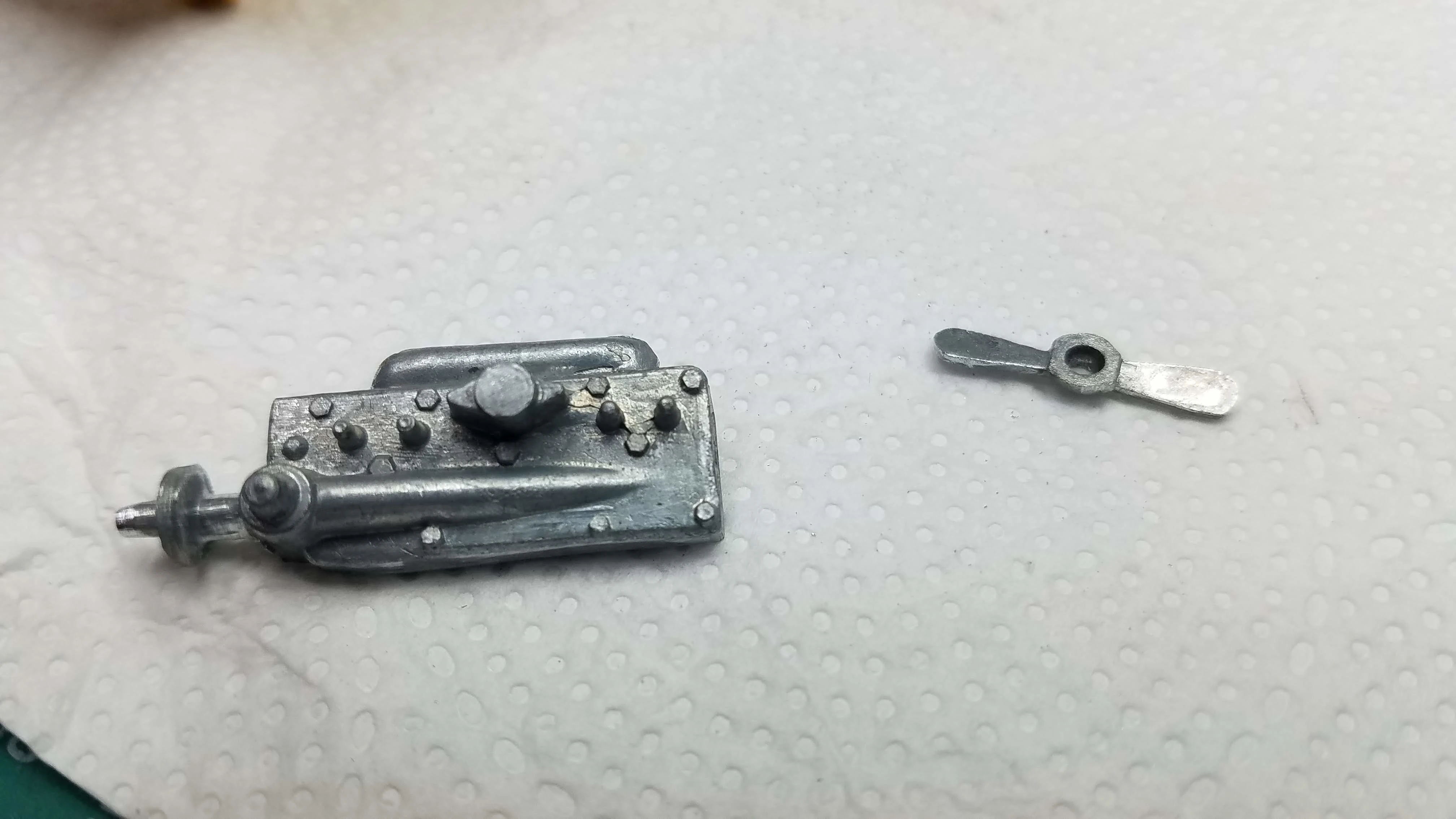
I don't have a before picture of the fan blade, but before removing all the flash and mold marks I couldn't tell that it was a fan. Now at least it looks like a two bladed fan. The head needed a lot of cleanup. The shaft where the fan mounts was too large due to mold lines. Also, I might have to "machine" the head and block to make the head fit flush against it.
5 of 50
I know I might be repeating myself, and I'm not complaining, but here is the frame with the rear differential and rear axle attached. It can be seen where cleanup is occurring by the shiny areas.
6 of 50
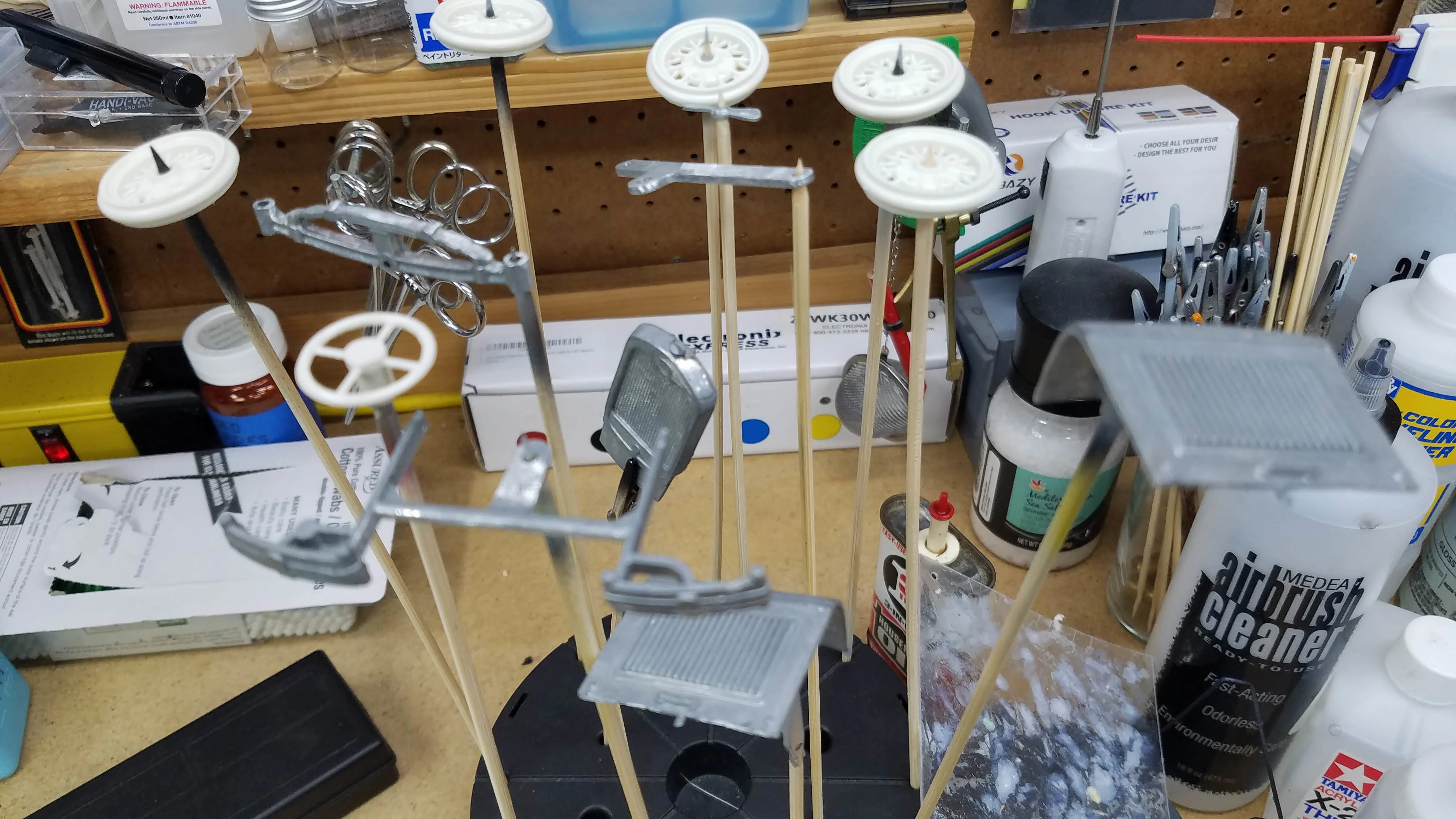
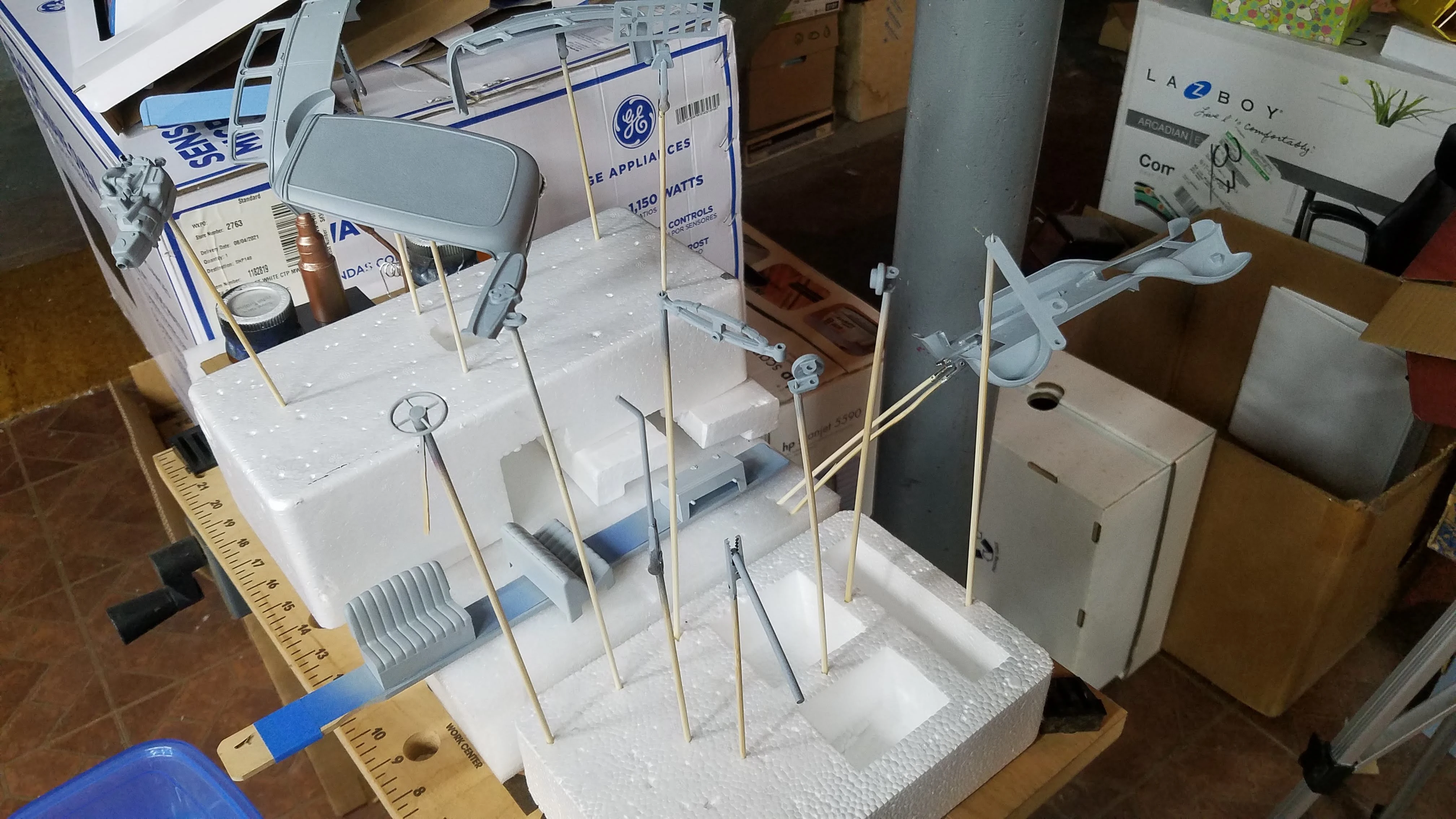
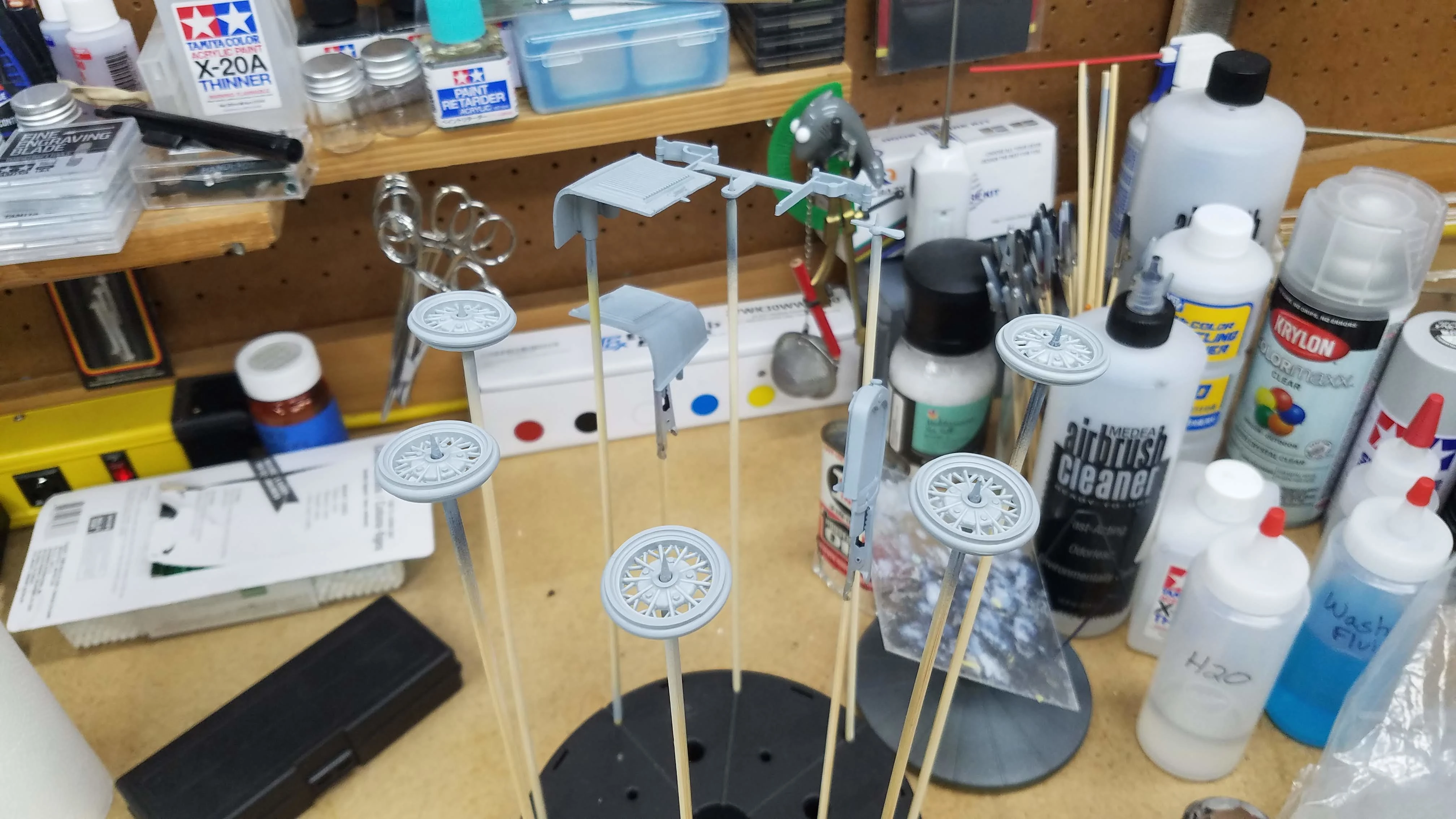
Some of the parts are on sticks and ready for primer to be applied. I will not be priming until all parts are cleaned and rubbed down with #0000 steel wool.
7 of 50
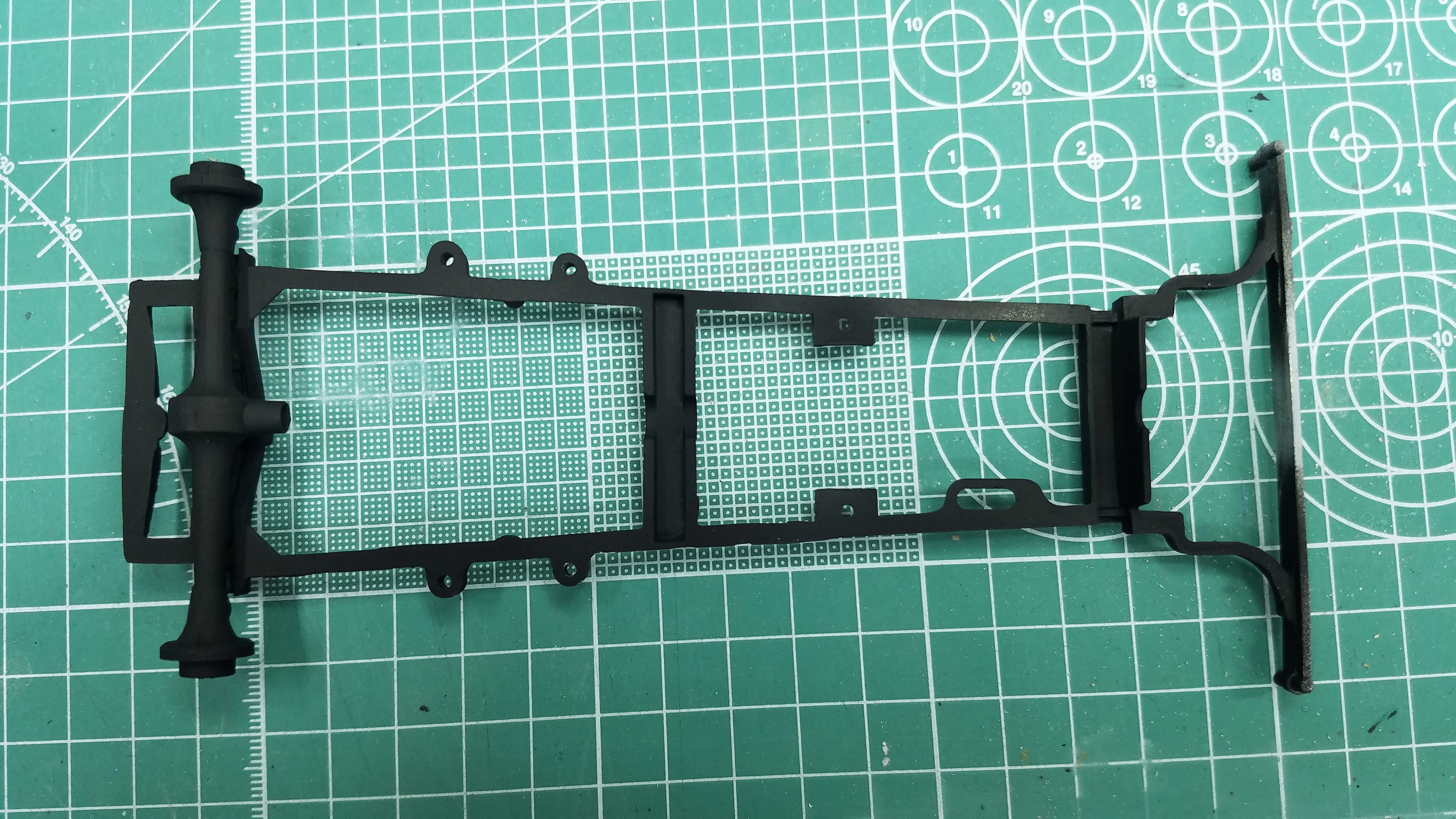
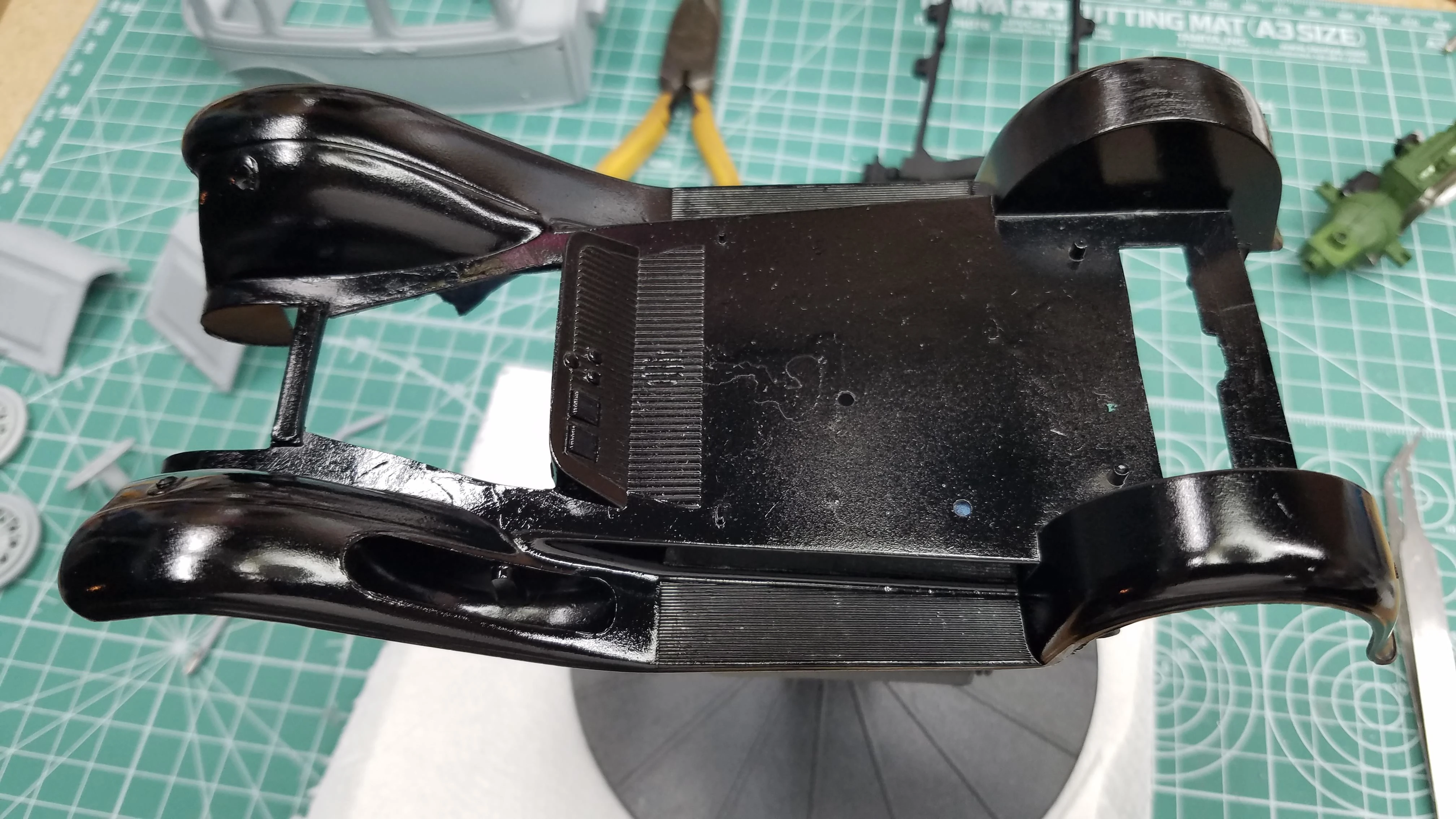
This is the bottom of the Fender-Frame assembly. There were/are a lot of injector pin marks and molded in text that needed to be removed. This picture shows the text has been removed that was located just above the muffler and tail pipe. There are large injector pin marks in the fender wells. They need to be removed and are going to be difficult because there is not a lot of room, especially to fit a Dremel tool bit.
8 of 50
Another shot of the Fender-Frame assembly showing more injector pin marks and some of the text that is still being removed.
9 of 50
The injector pin marks under the front fenders are huge and again...getting a tool in there to clean them off will be difficult and time consuming. I ended up using the pointed Dremel grinding bit.
10 of 50
Holes need to be drilled in the rear fenders. I'm sure it is to mount the tail lights. I marked the center points and used a center punch to make a dimple. I then drilled a pilot hole with a 1/16" drill bit. The finished hole is then drilled with a 3/32" drill bit. The photo shows the left fender with the pilot hole drilled and the right fender with the center punch dimple.
11 of 50
All parts that need priming have been primed.
12 of 50
More parts that have been primed.
13 of 50
More parts that have been primed.
14 of 50
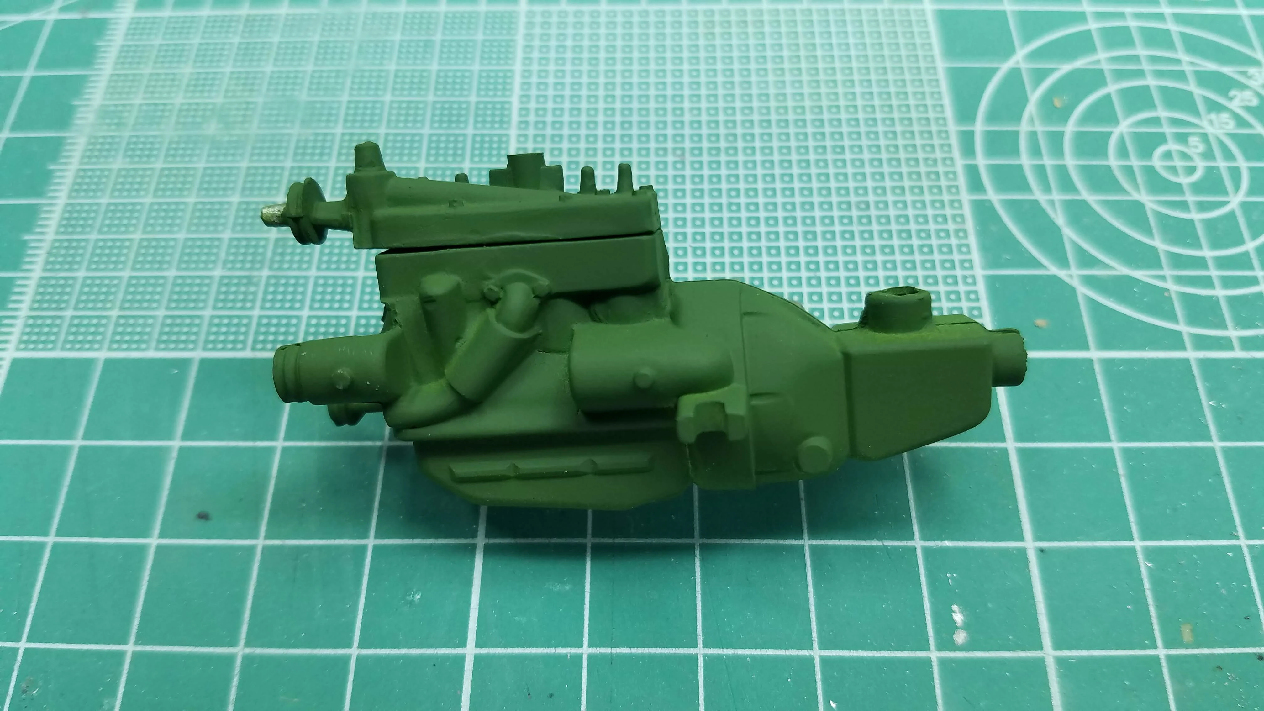
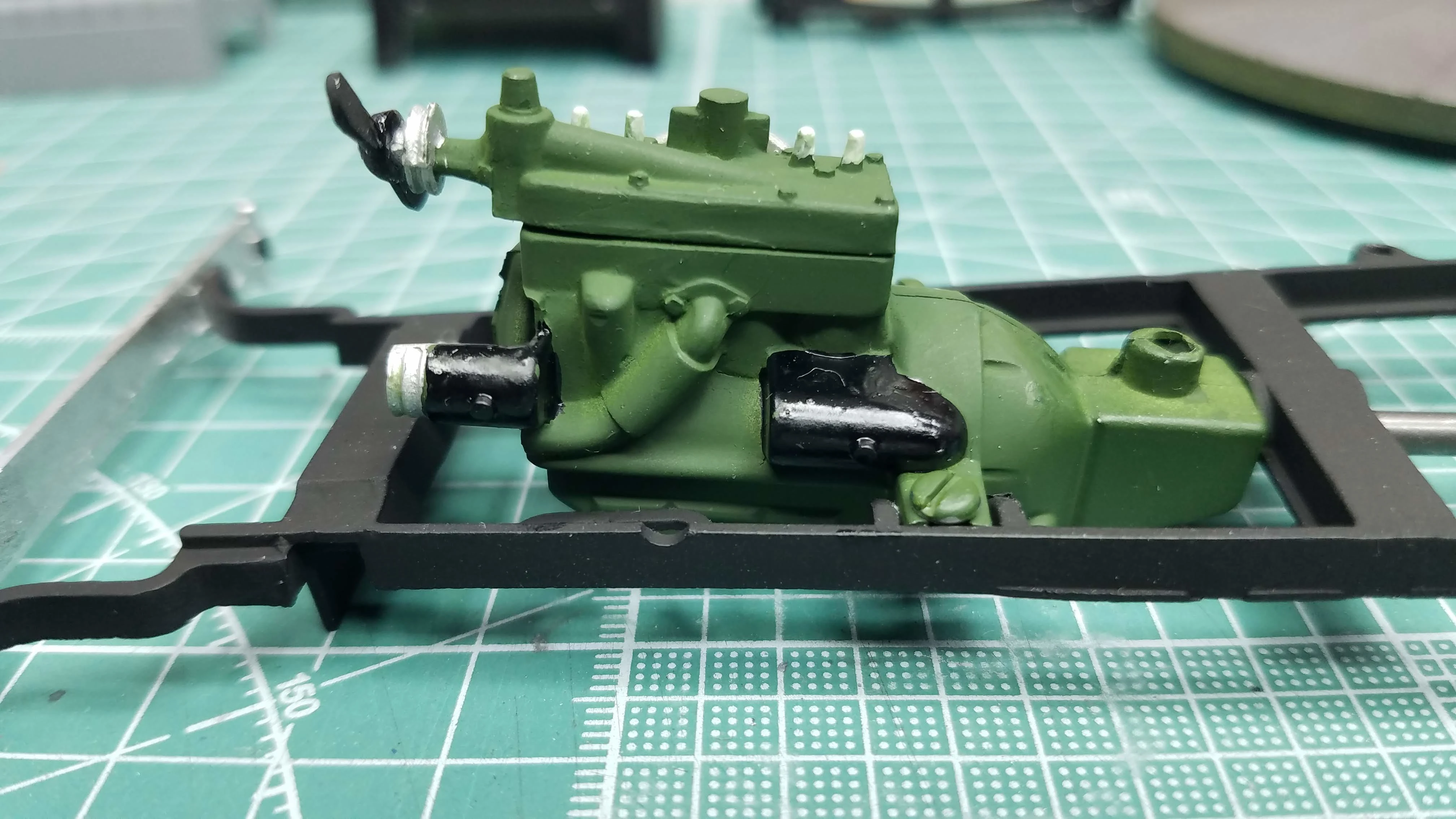
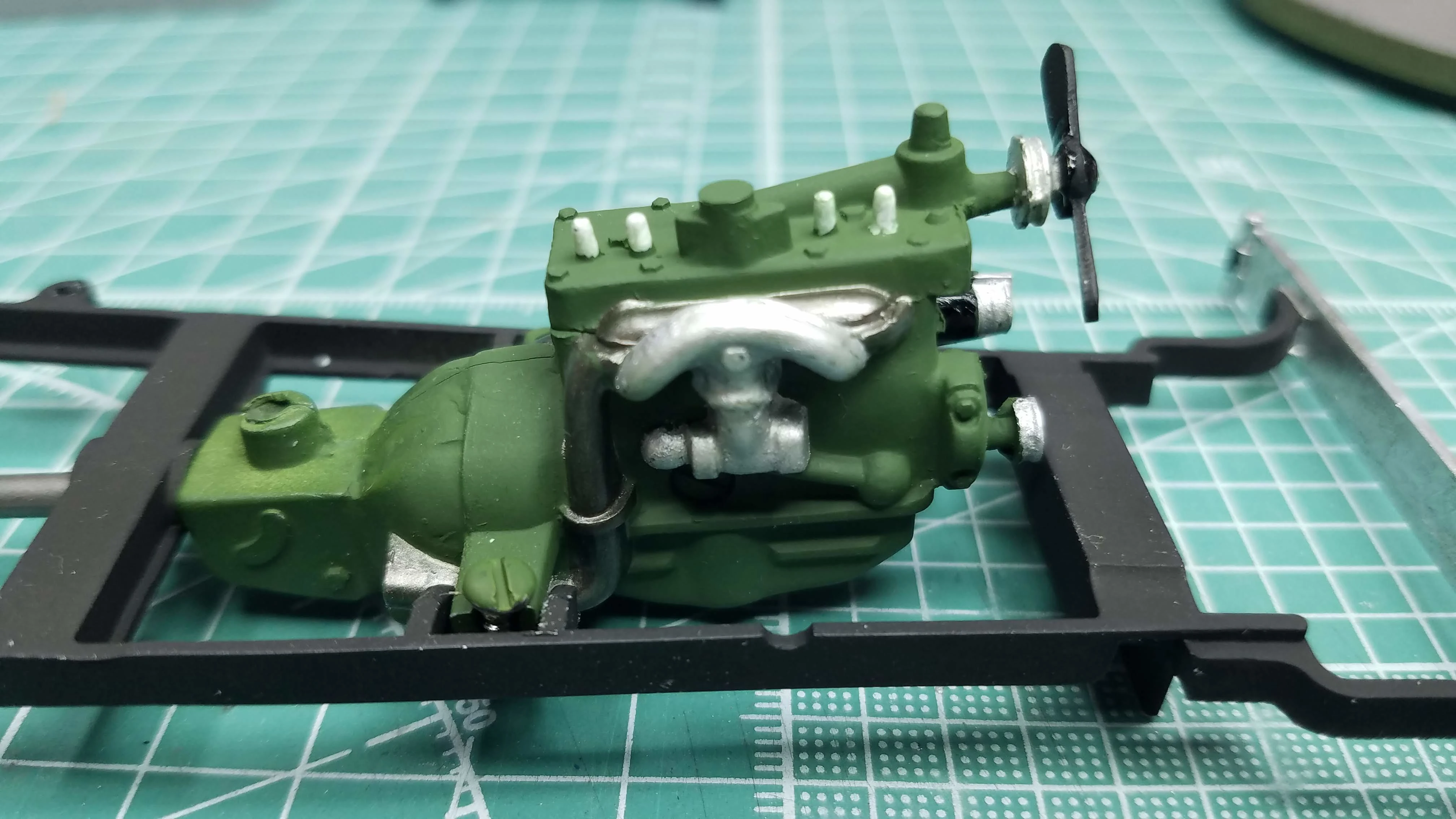
The engine has been painted with Tamiya XF-5 Green. In the late 1920's and early 1930's, many of the Model 'A' engines were green. This shows the left side of the engine. Some detail will be painted later. As can be seen, there is still a gap between the head and the block. This is the best I was able to get it while maintaining structural integrity.
15 of 50
Another view of the engine.The engine has been painted with Tamiya XF-5 Green. In the late 1920's and early 1930's, many of the Model 'A' engines were green. This shows the right side of the engine. Some detail will be painted later.
16 of 50
The frame, rear suspension, axle and wheel hubs are assembled and painted with Tamiya XF-1 Flat Black.
17 of 50
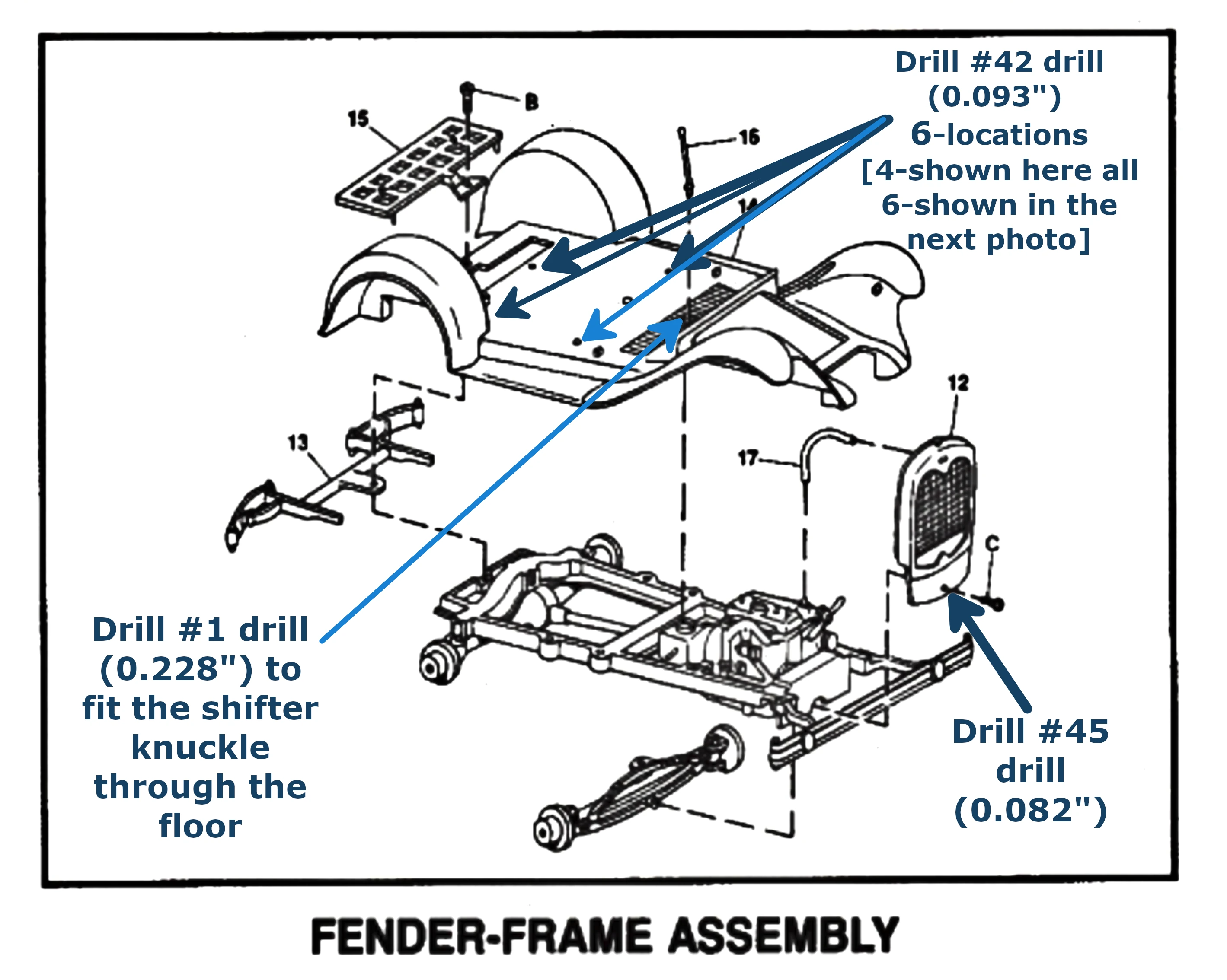
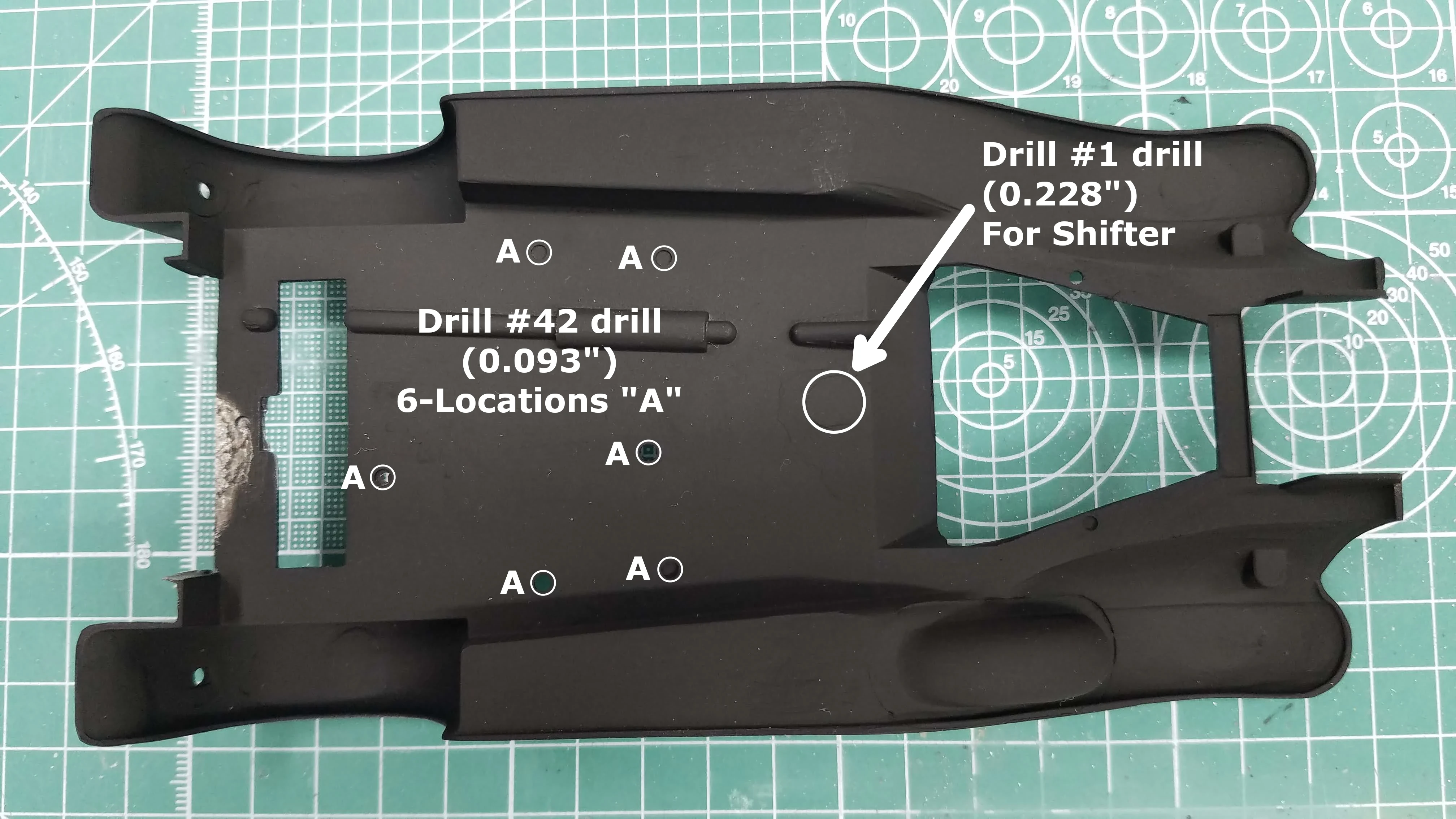
Fender-Frame assembly diagram showing some of the holes that may need to be drilled open. On my Fender-Frame assembly five of the six locations had to be drilled opened using a #42 drill (0.093"). I also had to drill open the radiator mounting hole. The whole was there; however, it was too small to accept the screw. I drilled it open with a #45 drill (0.082"). The next photo shows a better view of the location of these holes.
On the floor pan, where the shifter goes through to the transmission, the floor is marked for where the shifter goes through the floor; however, the hole needs to be drilled. I spotted the center and drilled a pilot hole. I then worked my why up to the final drill size using five different drill sizes. The final hole was drilled with a #1 drill (0.228"). It's important to work up to the final drill size so that the hole remains round and does not start to look like a rounded side triangle. When the floor pan is placed on the frame, the protruding transmission shifter boot should protrude through the floor.
18 of 50
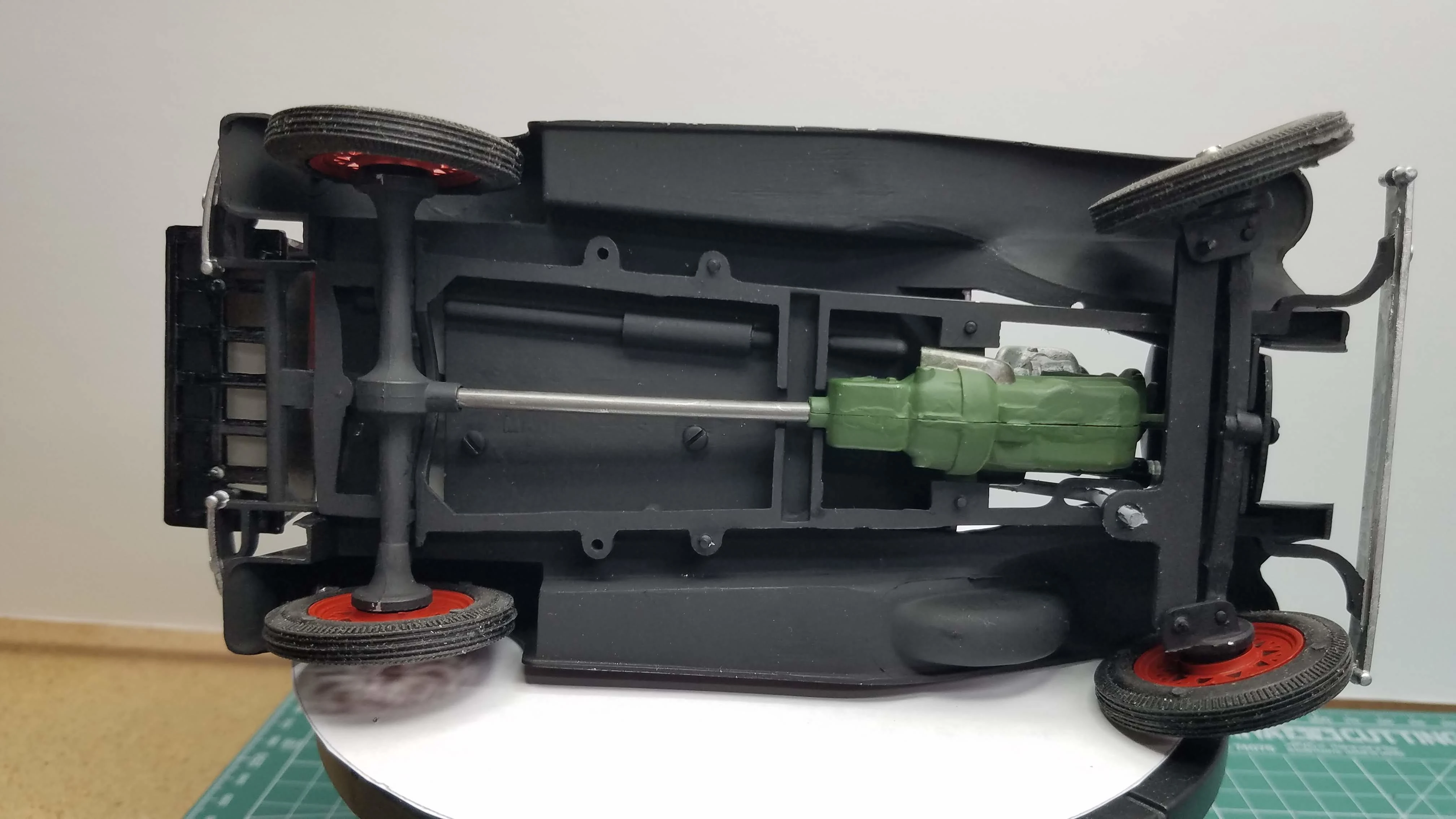
The bottom of the Fender-Frame assembly is painted with Tamiya XF-1 Flat Black. As shown in the previous photo, there are holes that might need to be drilled open. This picture gives a better view as to the location of these holes. There should be a round indentation as to where the hole should be located.
19 of 50
The top of the Fender-Frame assembly is painted with Tamiya X-1 Gloss Black. I did not fuse with the floor pan since it won't be seen.
20 of 50
For some reason, and I don't know why, I had trouble getting paint to properly adhere to the radiator. This photo shows the first attempt. It took three more attempts and it's still looks like crap. As you'll see later, I used Vallejo 77.707 Chrome over a Vallejo 77.660 Gloss Black on the front and sides of the radiator; however, I looks more silver than chrome.
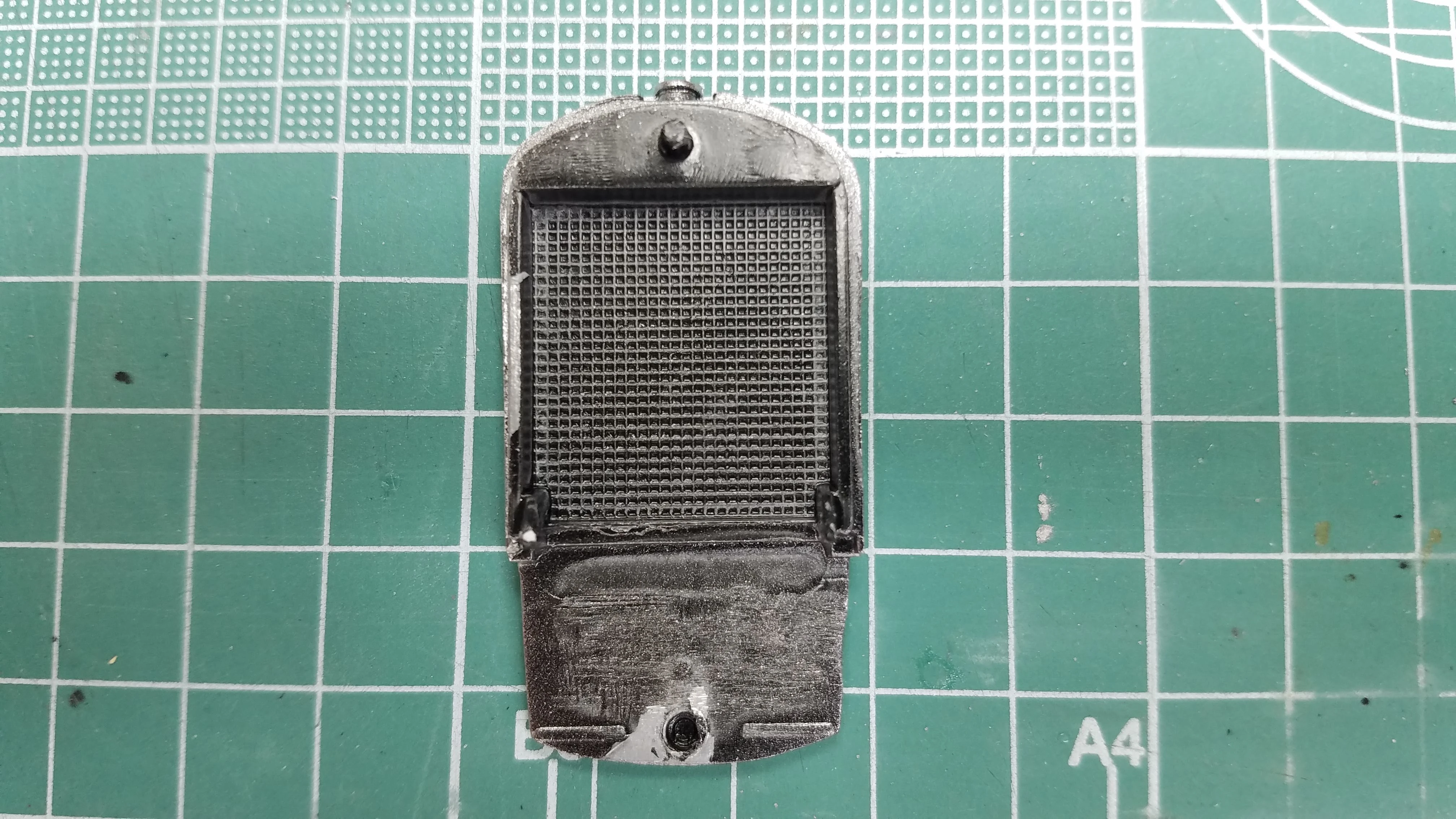
21 of 50
The body parts are primed with Vallejo 74.615 USN Light Ghost Grey Surface Primer. This photo is out of sequence since you can see that the radiator is still in primer in this shot.
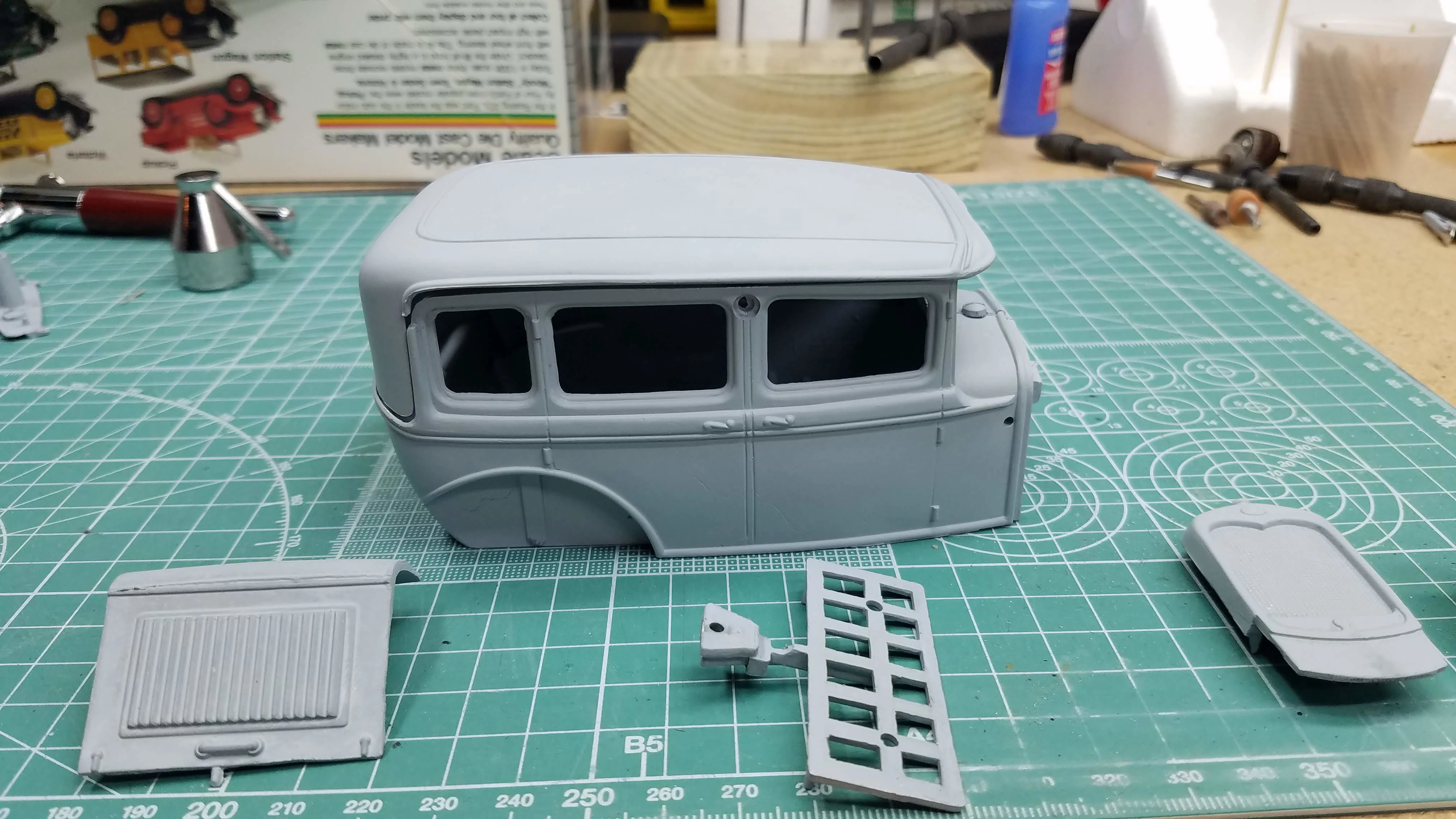
22 of 50
The engine is mounted in the frame. I added some detail to the left side of the engine. The starter, generator and fan blades are painted with Tamiya X-18 Semi-Gloss Black and the pulleys are painted with Tamiya XF-16 Flat Aluminum.
23 of 50
I added some detail to the right side of the engine. The intake manifold is painted with Tamiya XF-16 Flat Aluminum and the exhaust manifold and pipe are painted with Vallejo 77.723 Exhaust. The spark plugs are painted with Tamiya X-2 White.
24 of 50
This photo was taken before the engine mounting screws were painted to show the drive shaft installed. The drive shaft is painted with Vallejo 77.712 Steel. The front suspension is also shown before the screws are painted and before it is mounted to the frame.
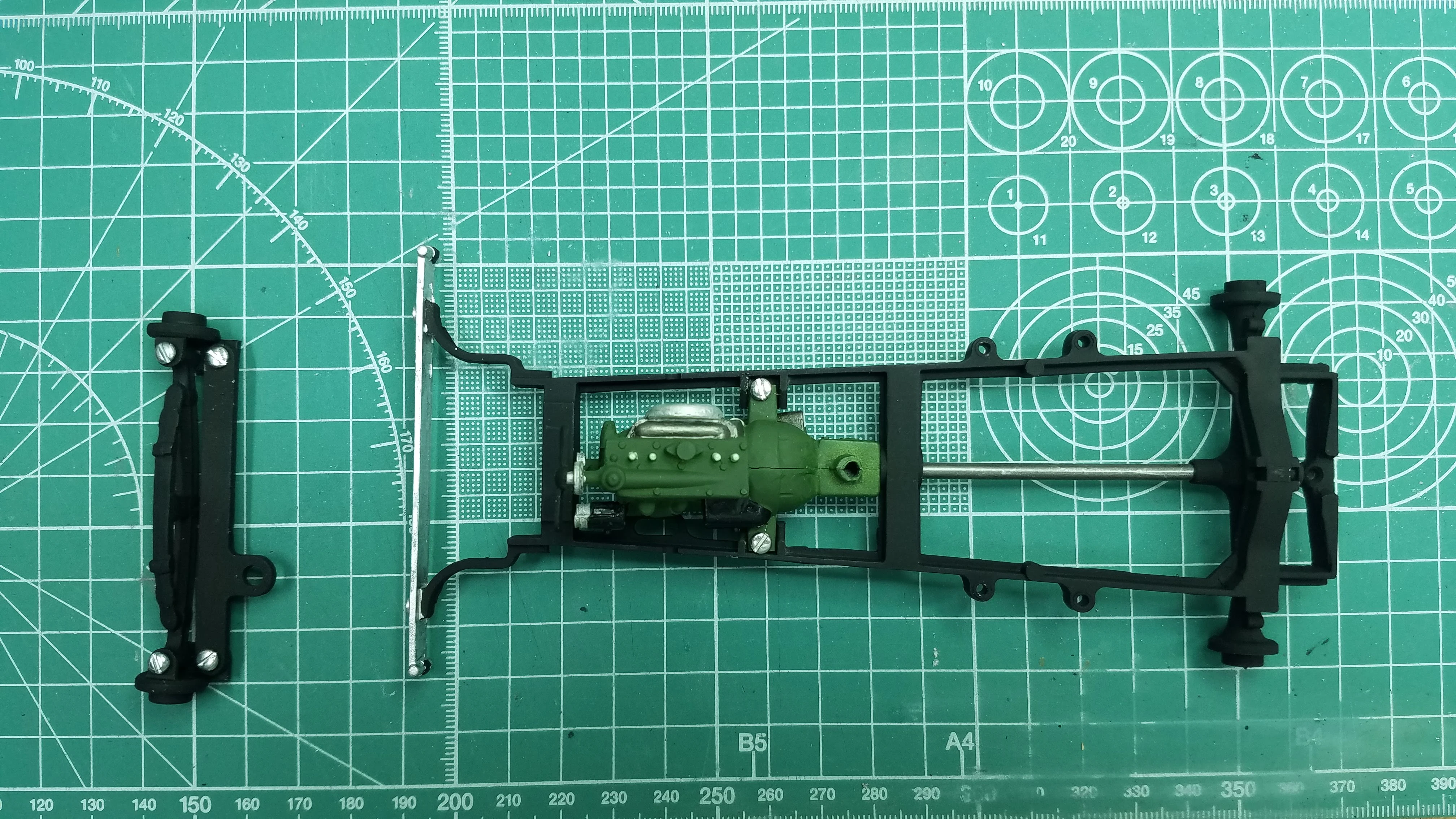
25 of 50
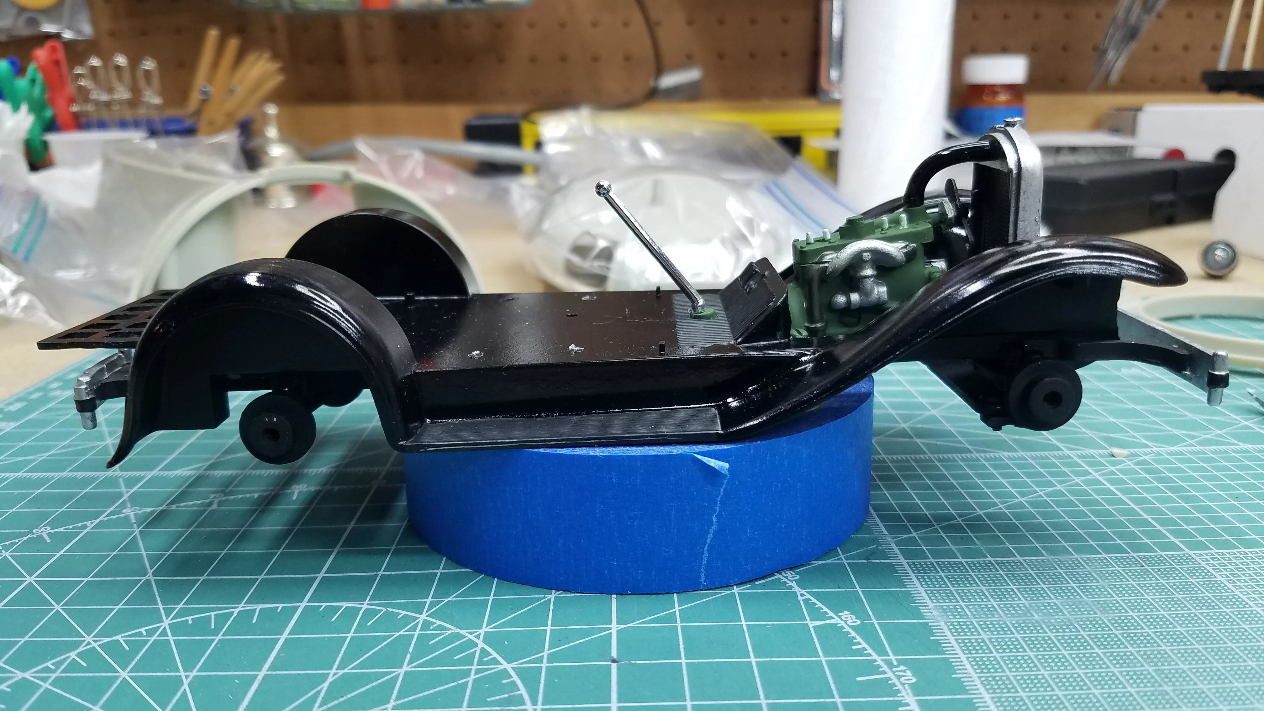
A left side view of the engine and drive shaft installed on the frame. Also shown is the front suspension before being installed into the frame.
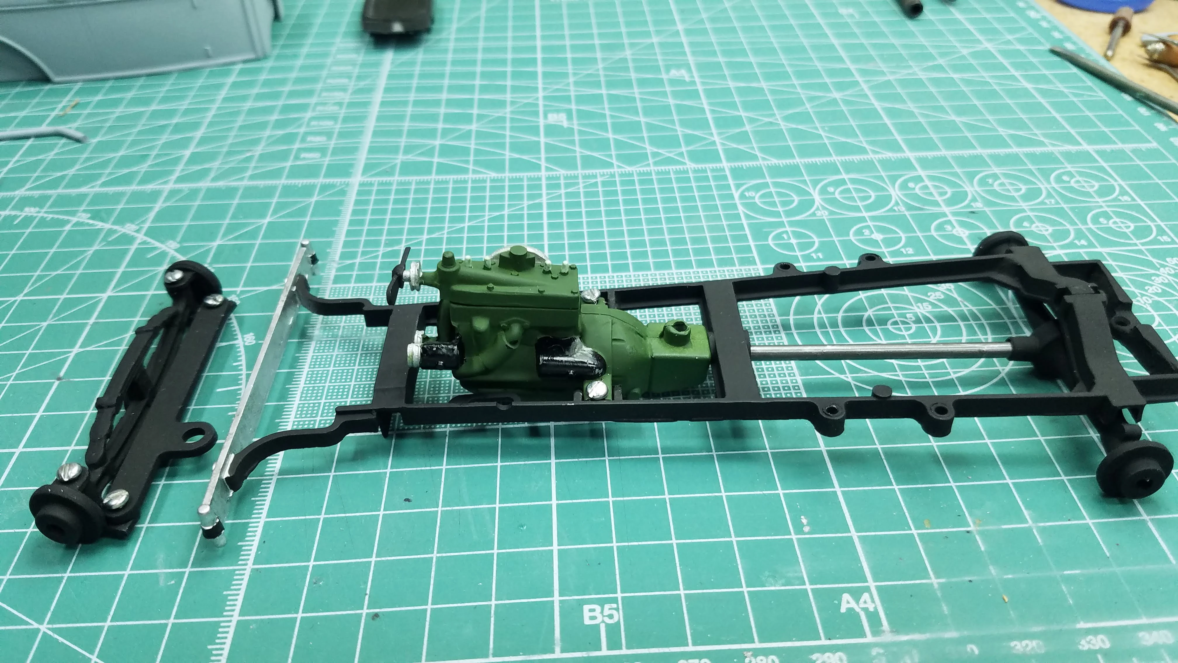
26 of 50
Left side view of the Fender-Frame Floor pan installed on the frame. This installation included the radiator, radiator hose, front suspension, luggage carrier, rear bumper and shifter. All these parts need to be installed together because of the way the screws hold them in position.
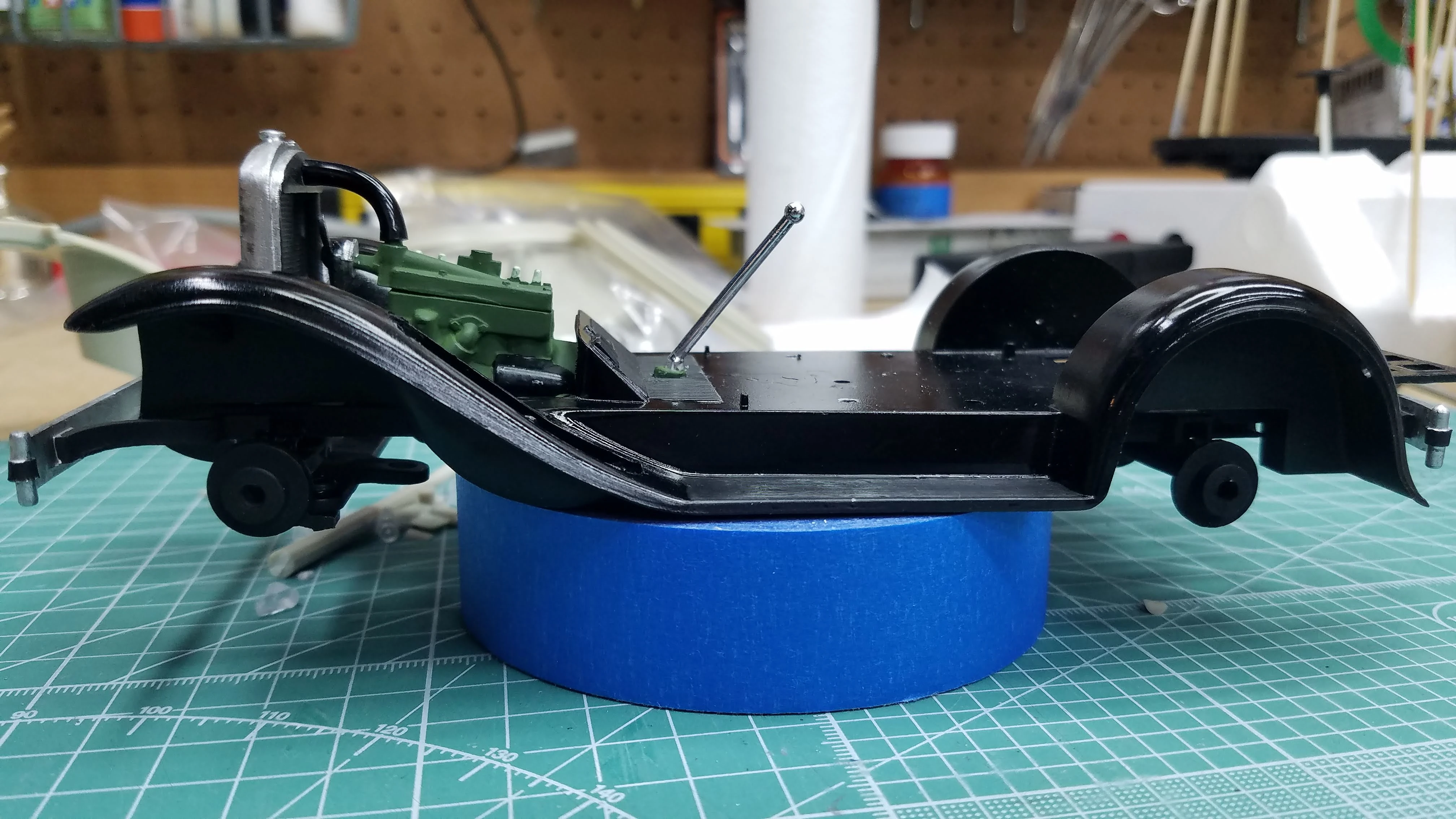
27 of 50
Right side view of the Fender-Frame Floor pan installed on the frame. This installation included the radiator, radiator hose, front suspension, luggage carrier, rear bumper and shifter. All these parts need to be installed together because of the way the screws hold them in position.
28 of 50
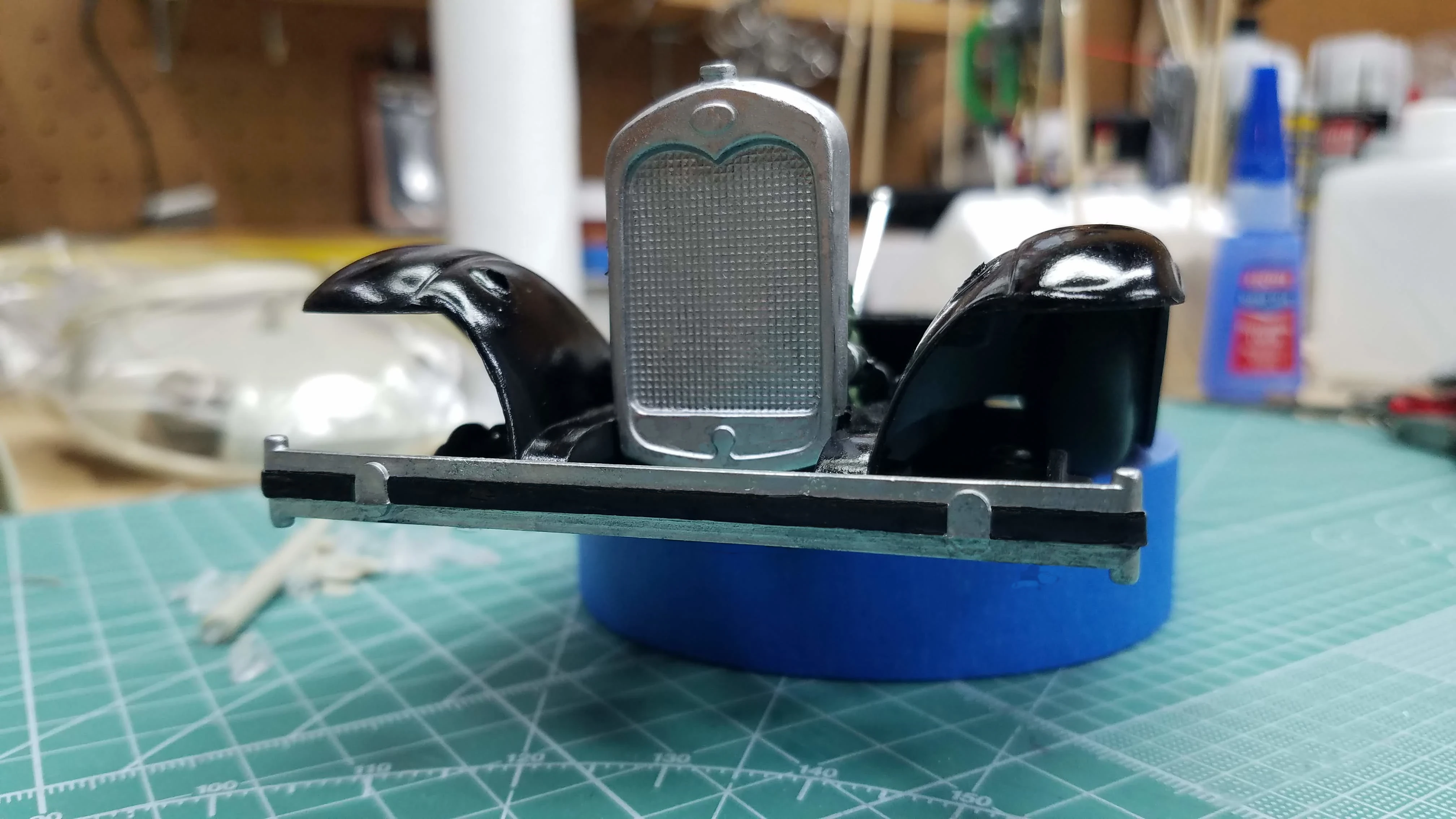
Front view of radiator, front bumper and front suspension installed. The bumper was painted with Vallejo 77.707 Chrome, which looks more silver than chrome. The back side bumper supports are painted with Tamiya XF-1 Flat Black and the bumper strip is painted with Tamiya XF-85 Rubber Black.
29 of 50
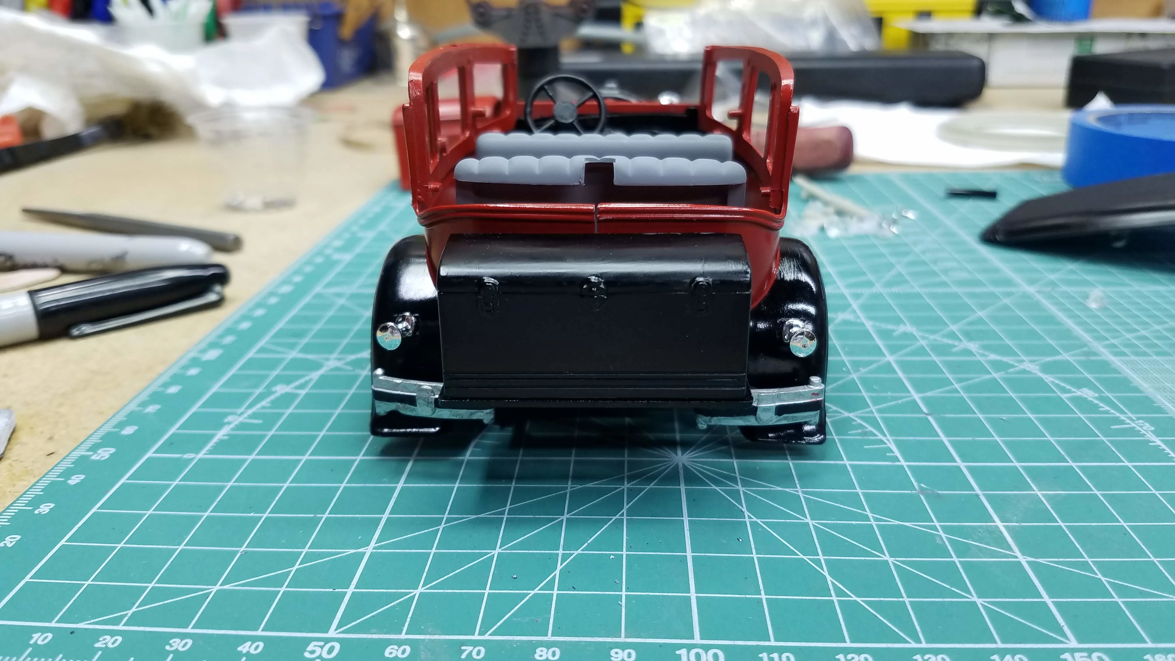
Rear view of the Fender-Frame, rear bumper and luggage carrier installed. The luggage carrier is at an angle but has been straighted after this photo. The luggage carrier is painted with Tamiya X-1 Gloss Black. The rear bumper is painted with Vallejo 77.707 Chrome and the bumper strip is painted with Tamiya XF-85 Rubber Black.
It's hard to see but the floor mat, peddles and running boards are painted with Tamiya XF-85 Rubber Black.
30 of 50
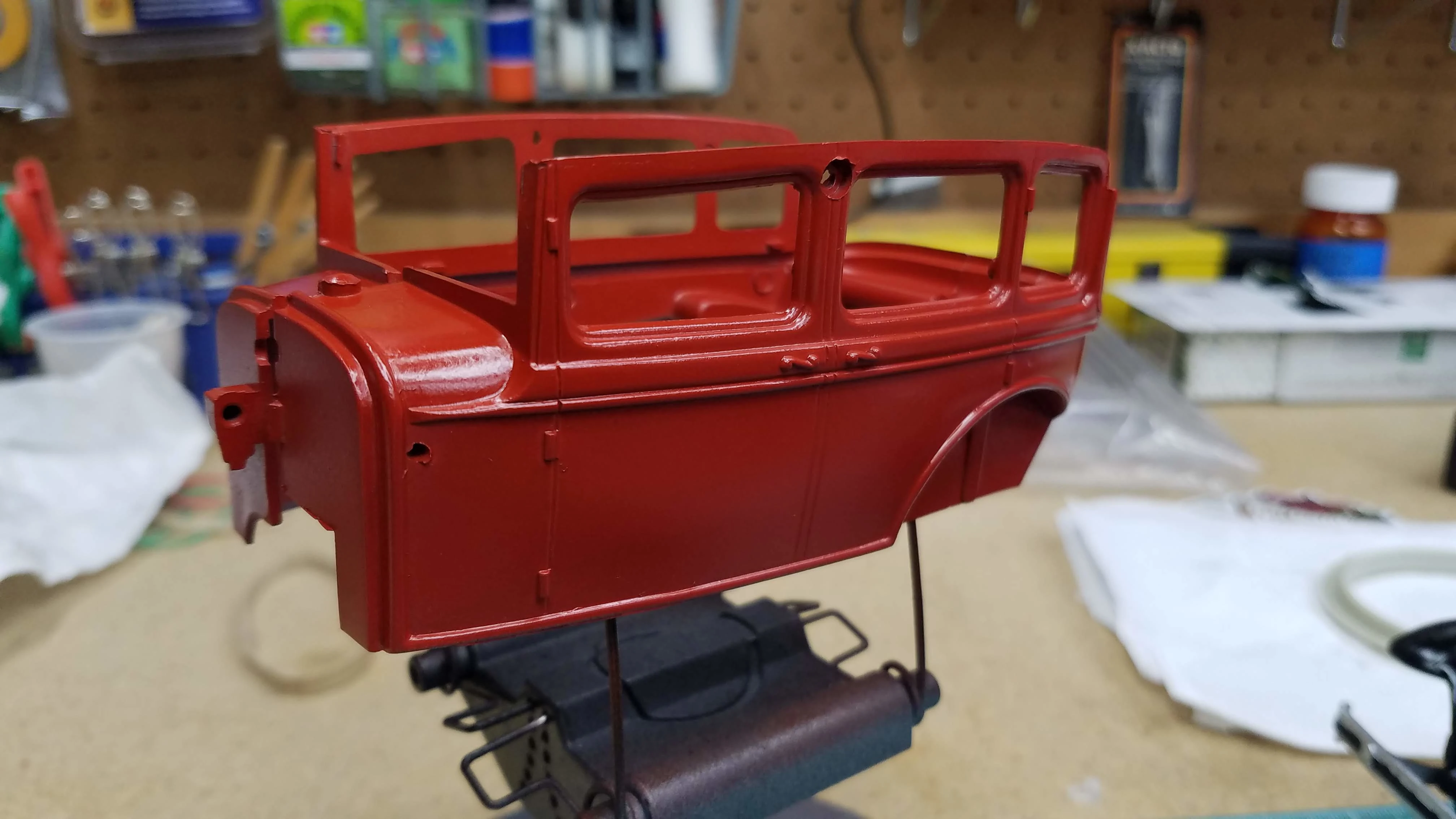
The body has been painted with Vallejo 71.084 Fire Red (Rojo Fuego). Vallejo paints dry to a flat finish; therefore, when the paint is thoroughly dry a gloss clear will be applied.
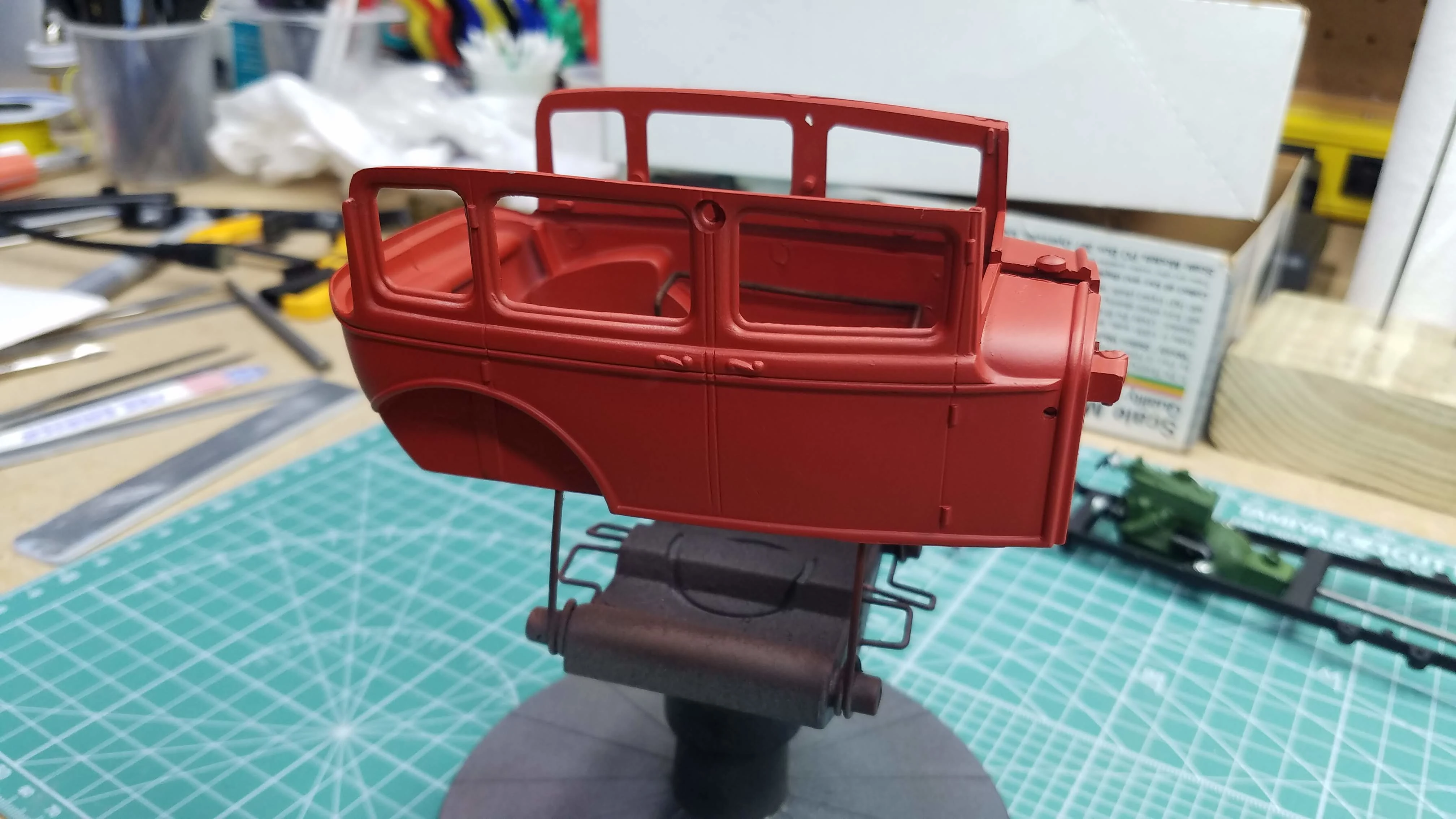
31 of 50
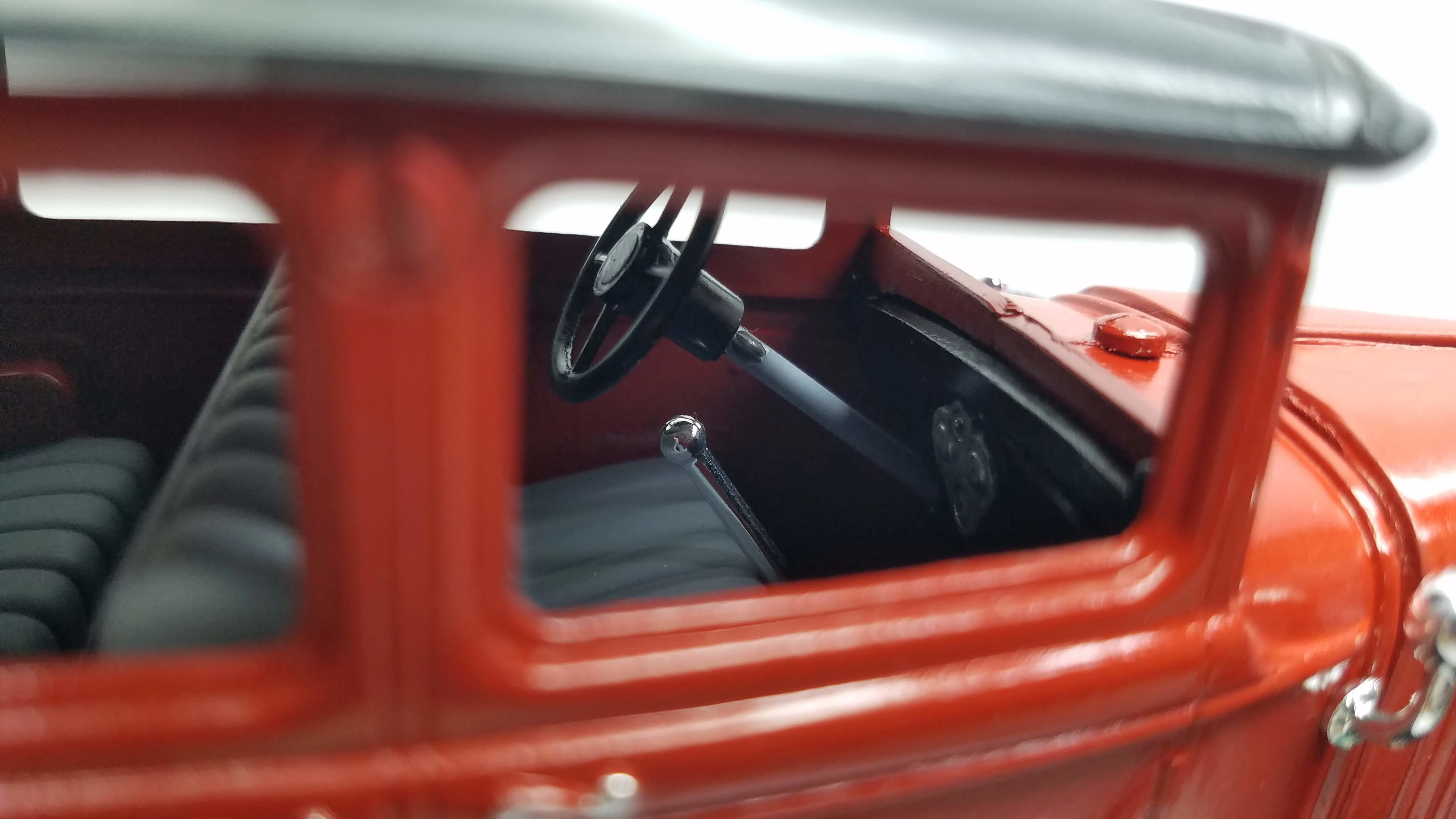
The left side of the hood was painted with Vallejo 71.084 Fire Red (Rojo Fuego) and is awaiting a gloss clear coat. The dash board was painted with Tamiya X-1 Gloss Black and the instrument cluster was chromed with a Molotow Chrome pen. The steering wheel was painted with Tamiya X-18 Semi-Gloss Black.
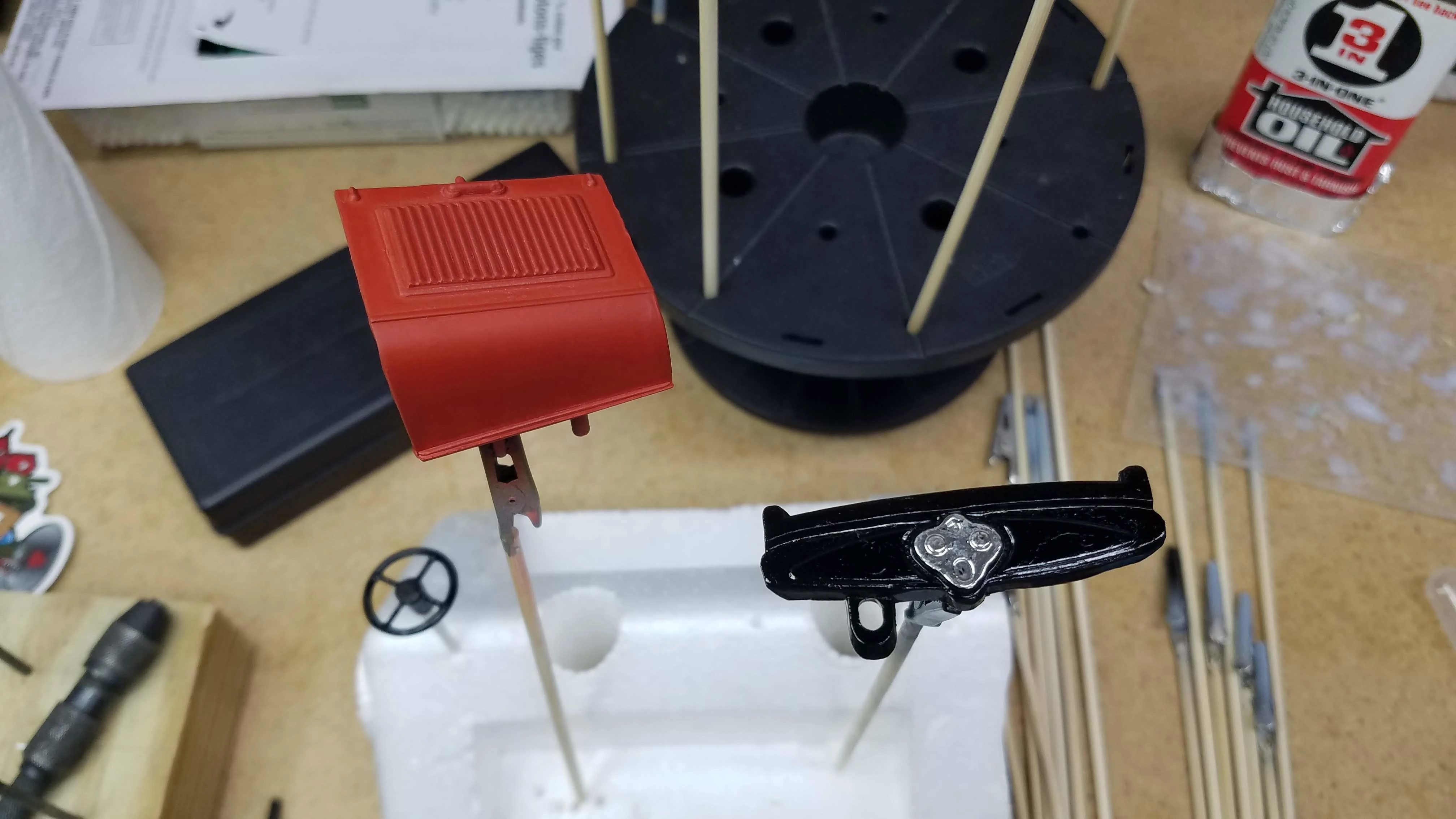
32 of 50
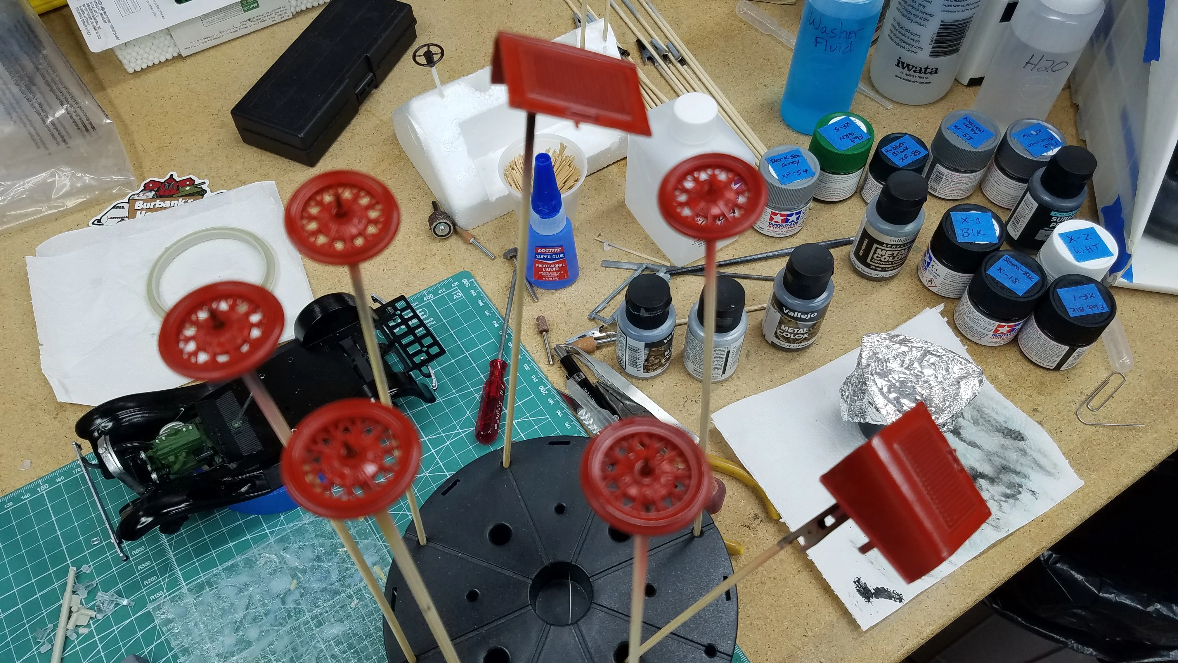
The wheels and right side of the hood have been painted with Vallejo 71.084 Fire Red (Rojo Fuego). Vallejo paints dry to a flat finish; therefore, when the paint is thoroughly dry a gloss clear will be applied.
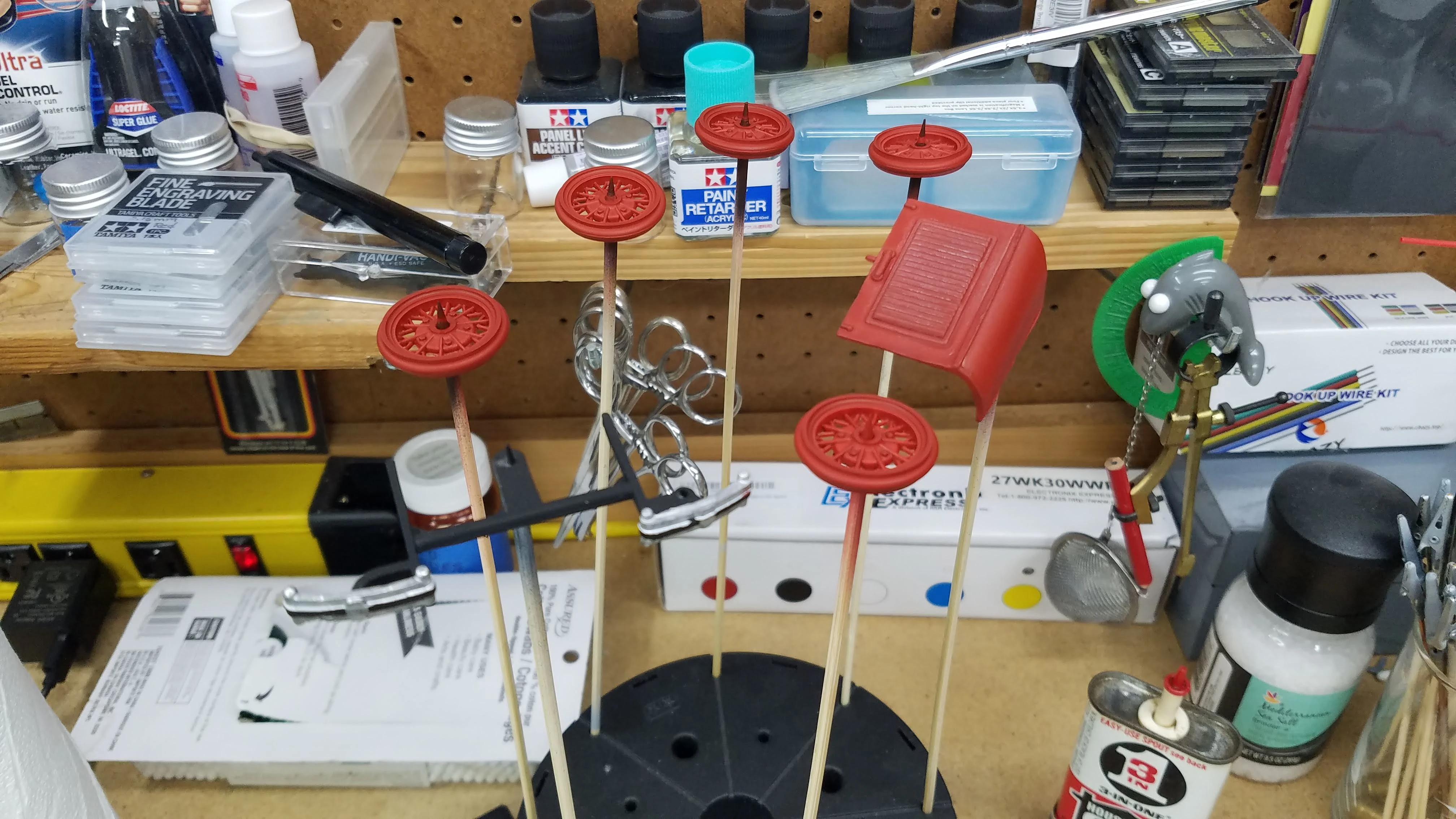
33 of 50
The seats are painted with Tamiya XF-54 Dark Sea Grey and the rear luggage bag was painted with Tamiya X-18 Semi-Gloss Black. The paint is still wet in the photo.
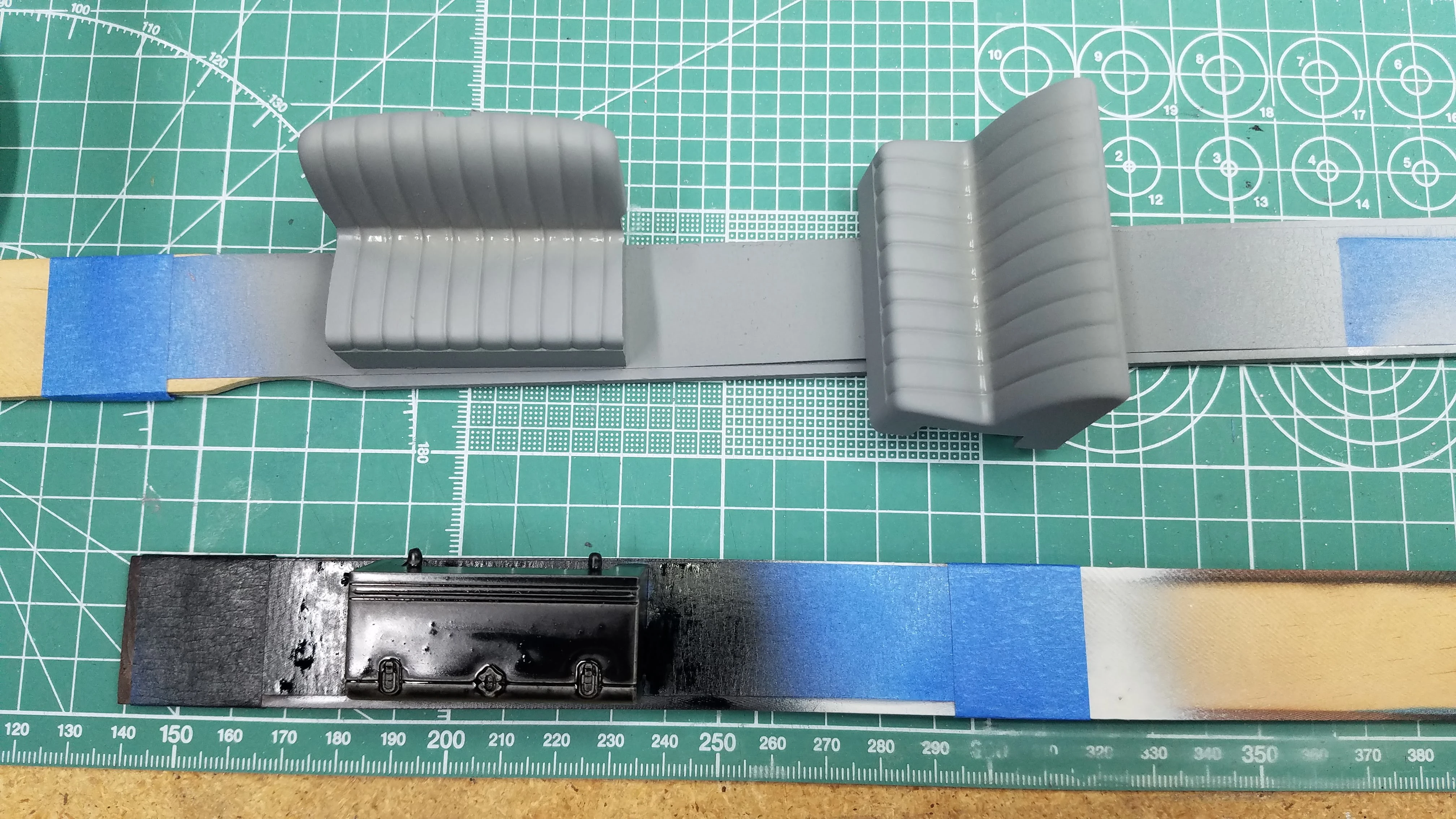
34 of 50
I used Krylon Gloss clear coat on the body. I painted the red with Vallejo 71.084 Fire Red (Rojo Fuego). Vallejo paints dry to a flat finish and therefore needed the gloss clear coat.
35 of 50
The wheels and hood were also painted with Vallejo 71.084 Fire Red (Rojo Fuego) and also received Krylon Gloss clear coat.
36 of 50
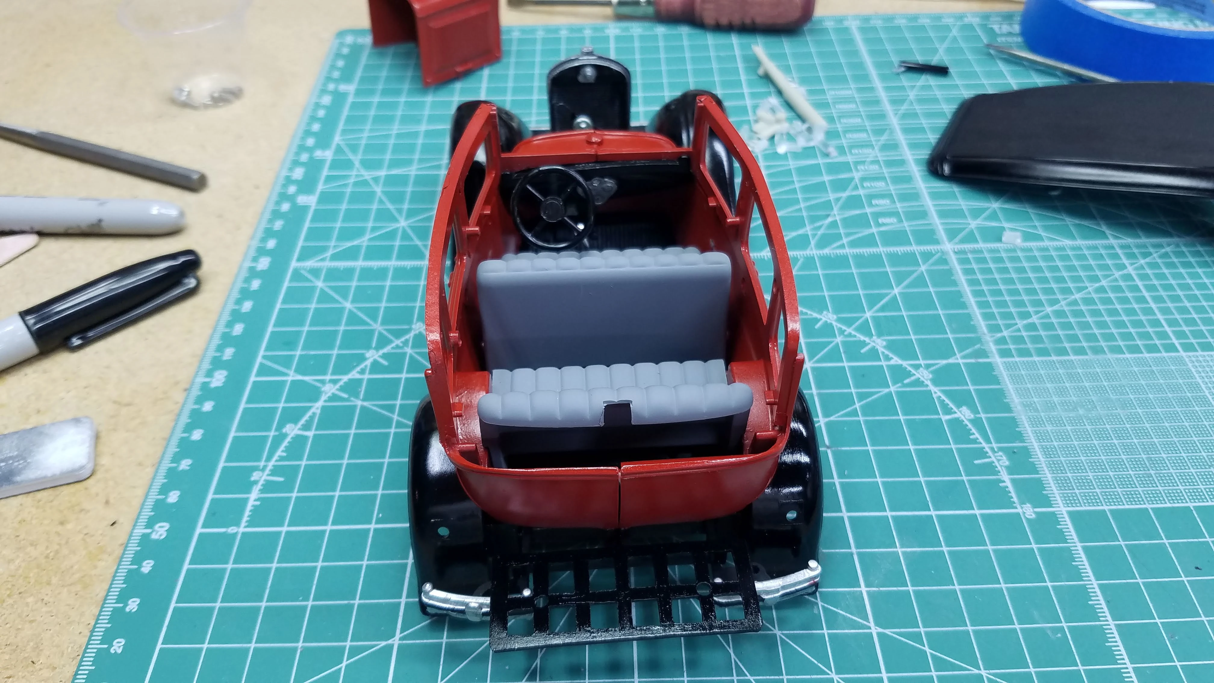
I started the assembly. Here is a view from the back of the car. I have the body on the frame-fender assembly, the dashboard mounted, the steering wheel steering post and the seats installed.
37 of 50
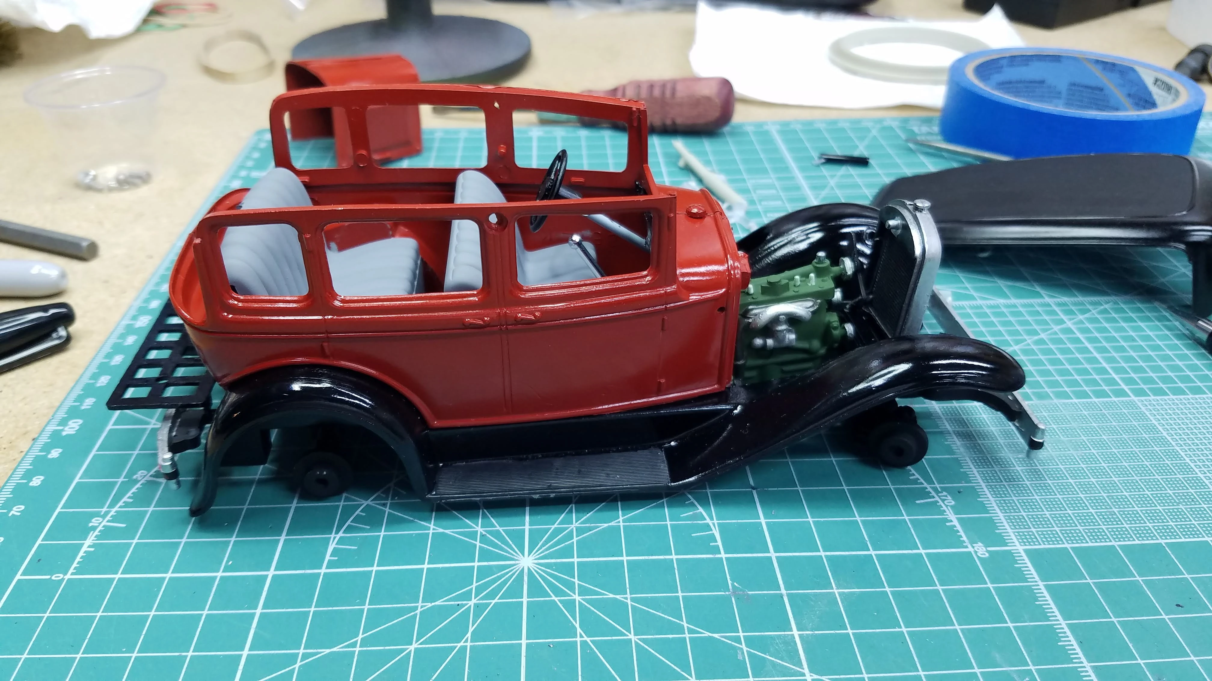
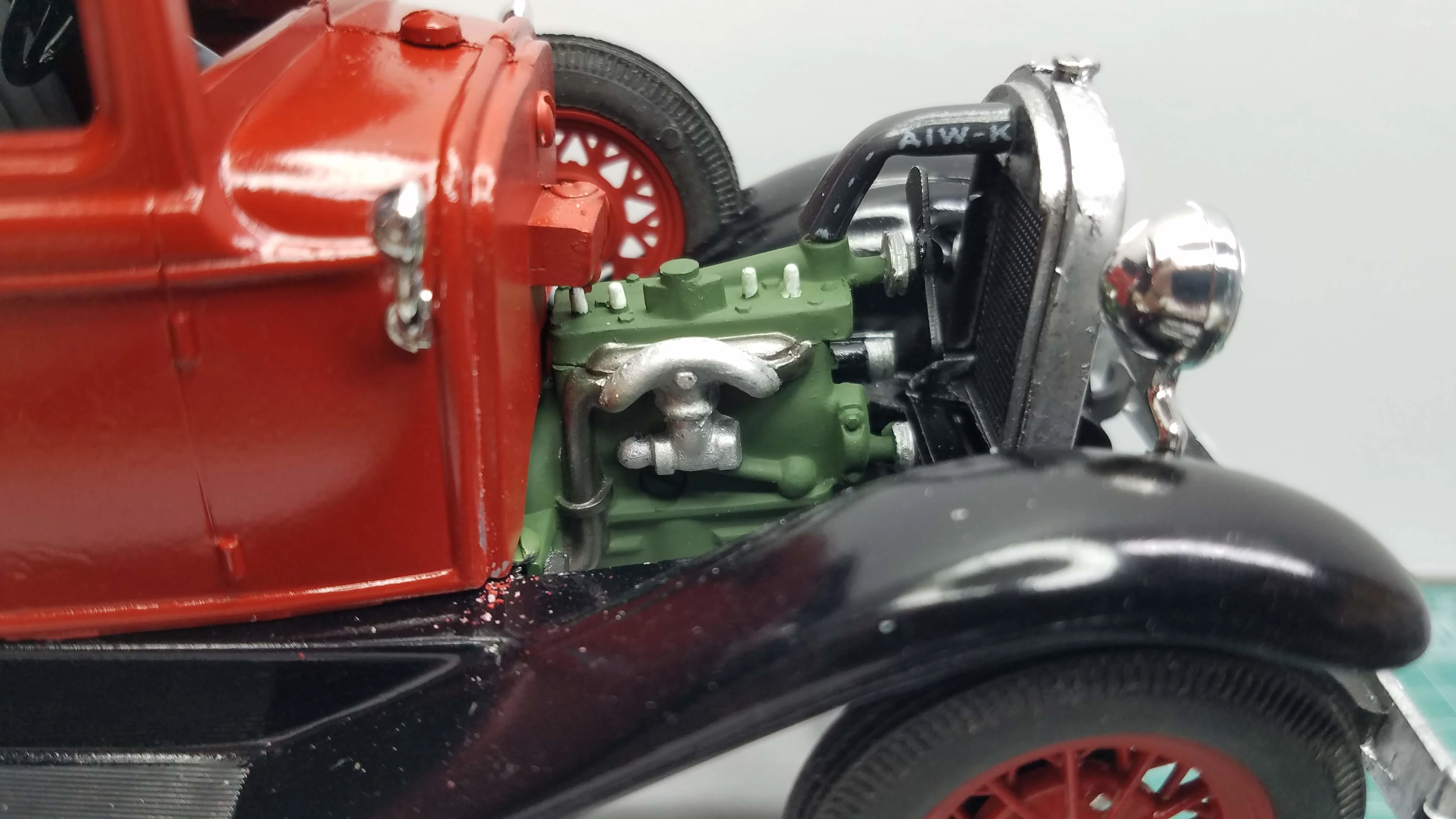
The assembly is in progress. Here is a view from the right side of the car. This view shows the engine, but also shows that the radiator is leaning forward. The screw that holds the radiator doesn't securely mount it in place and the elasticity of the radiator hose pushed the radiator forward. I fixed it with some Loctite.
38 of 50
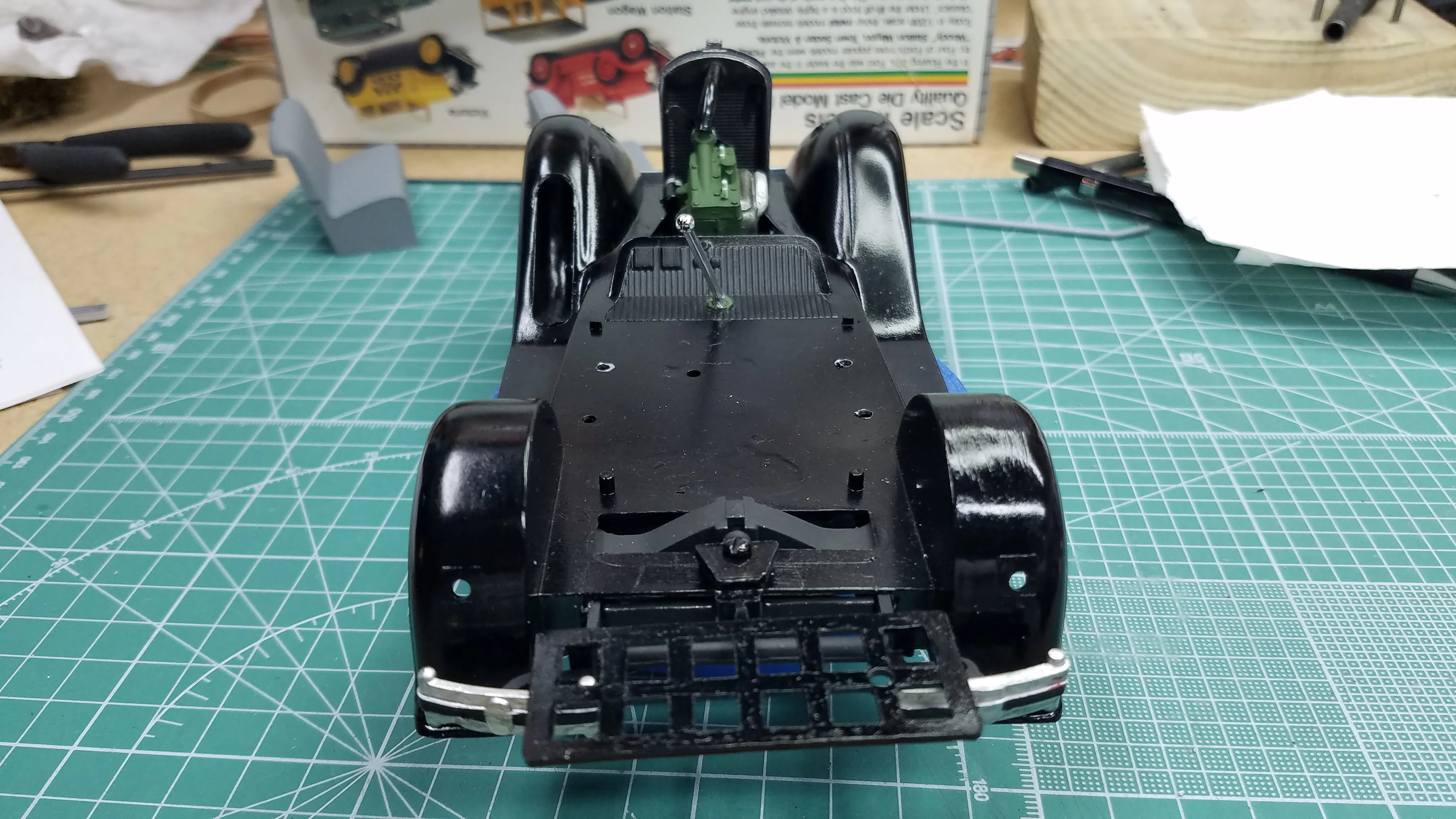
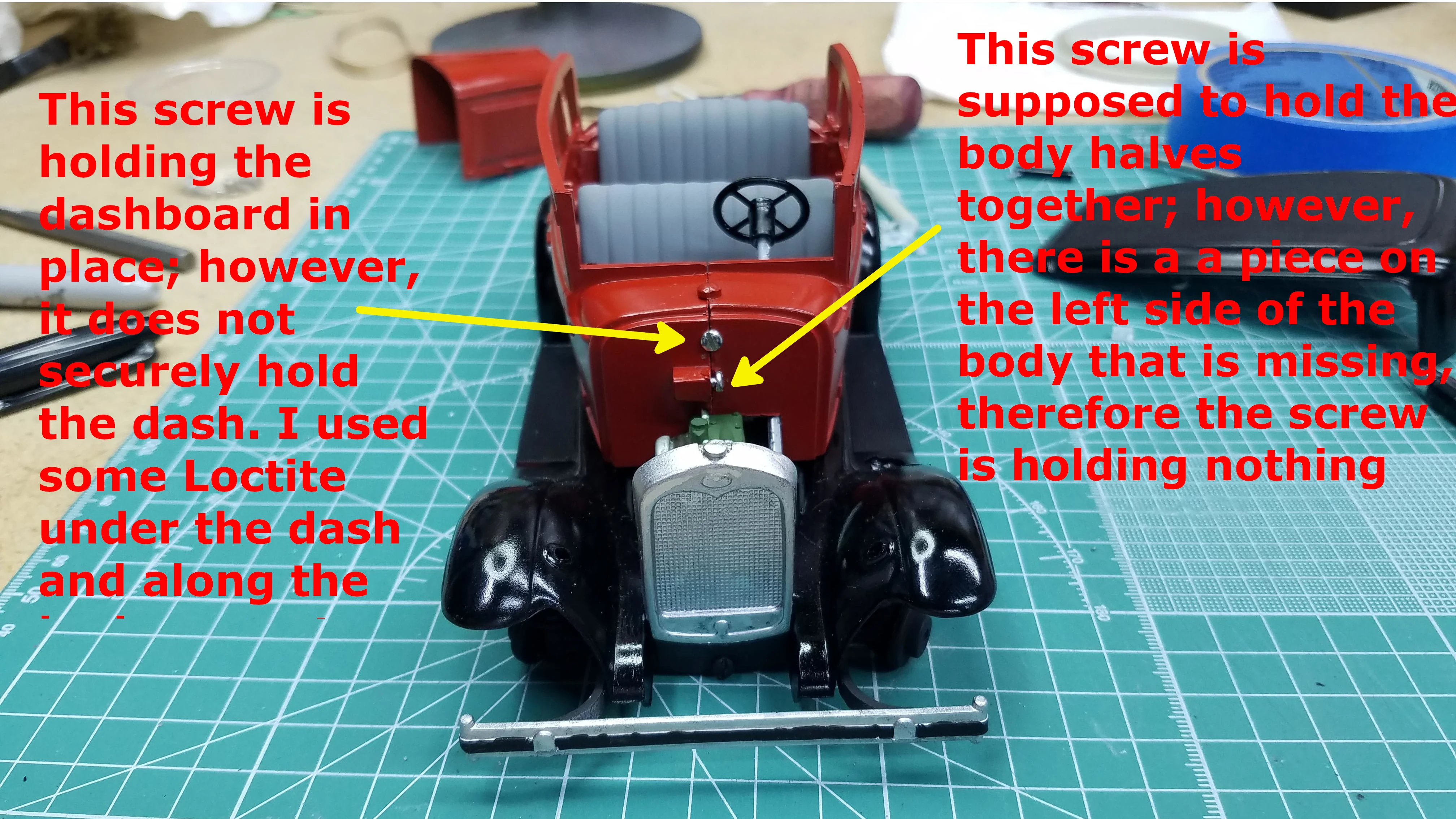
The assembly is in progress. Here is a view from the front. Two screws in and on the firewall will be painted red. As noted on the photo and in Part 04 of my YouTube video, these screws are not doing the job they are supposed to be doing.
39 of 50
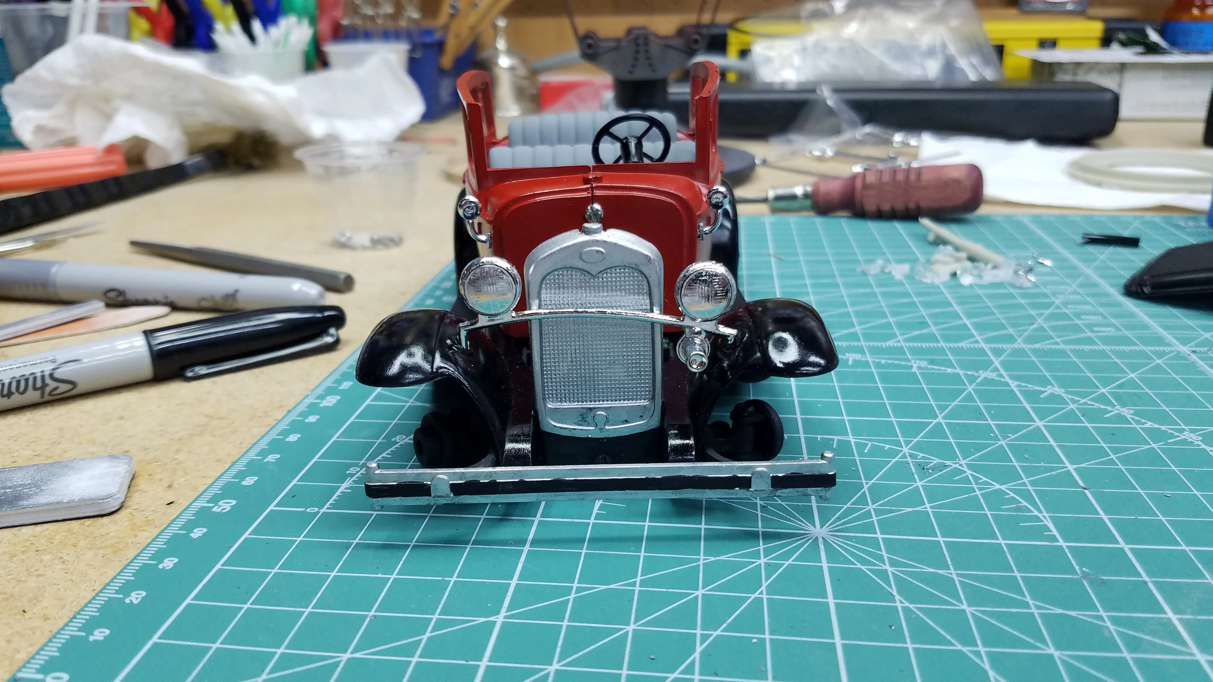
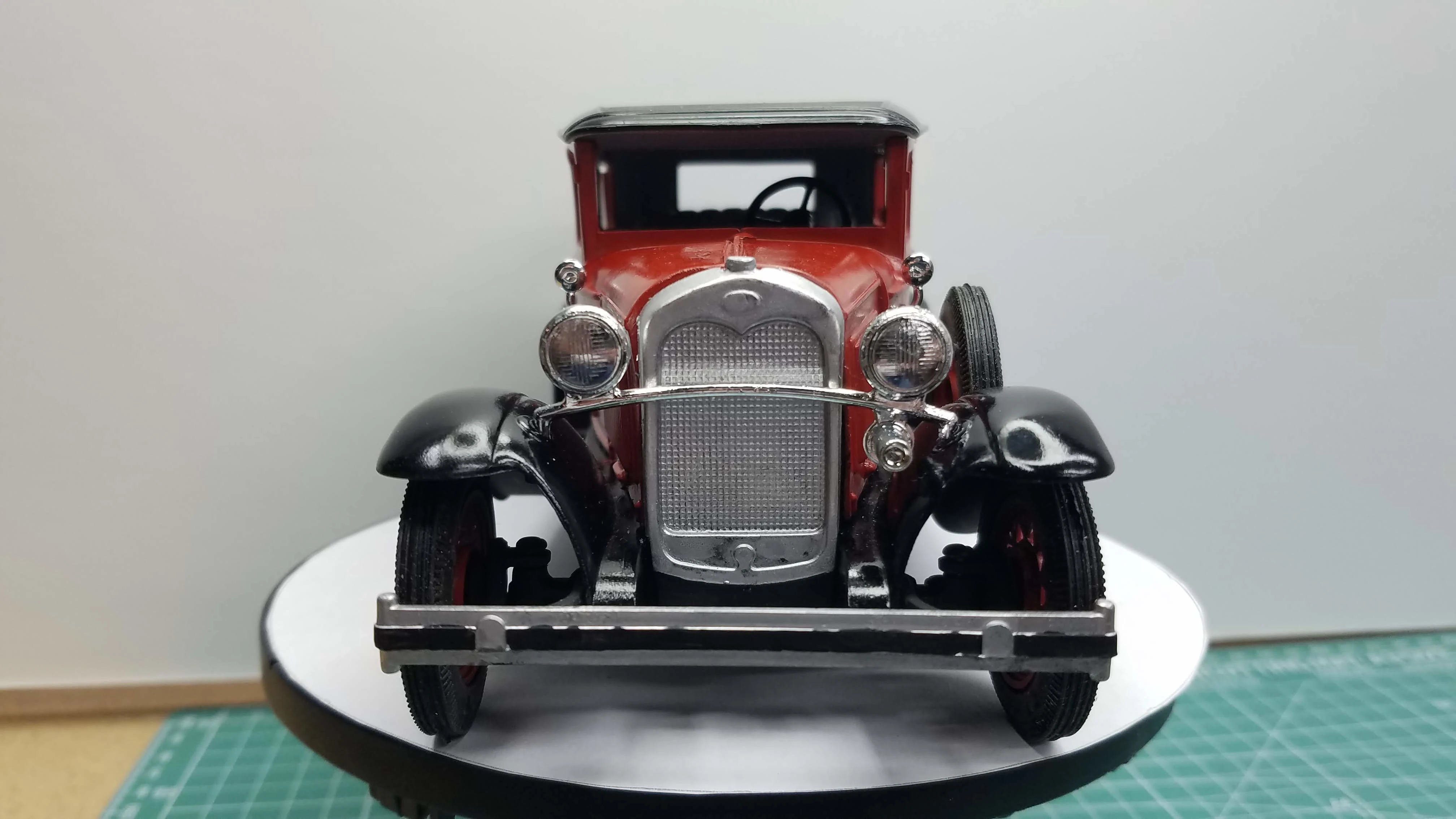
Front view with headlights and cowl lights installed. At this point the headlight bar is press fit into the fencers. The left side does not fully seat into the fender (right side in the photo).
40 of 50
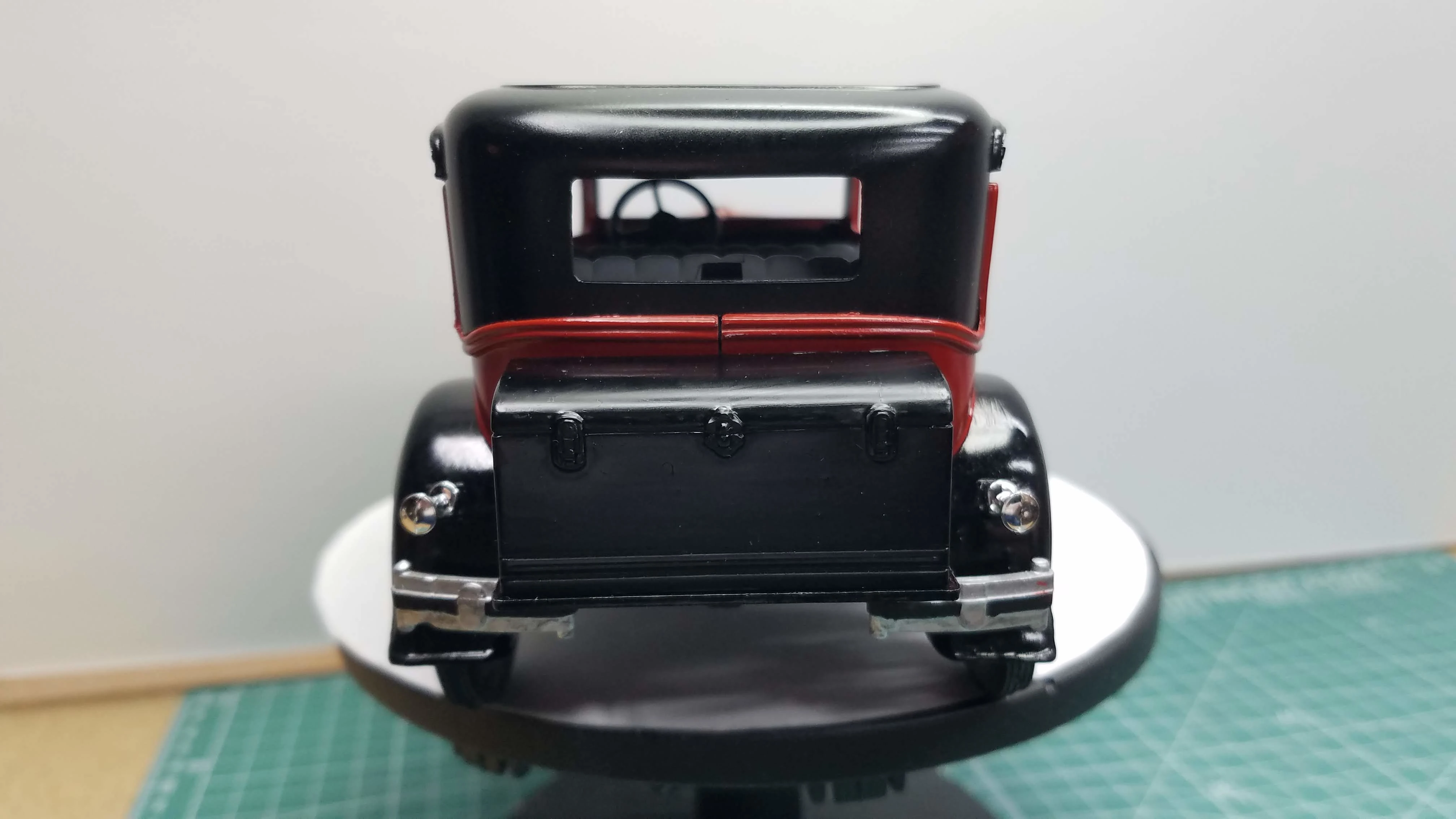
The trunk is installed on the luggage rack. It is held in place using Loctite. The tail lights are also installed. I might use some transparent red to make them look more realistic.
41 of 50
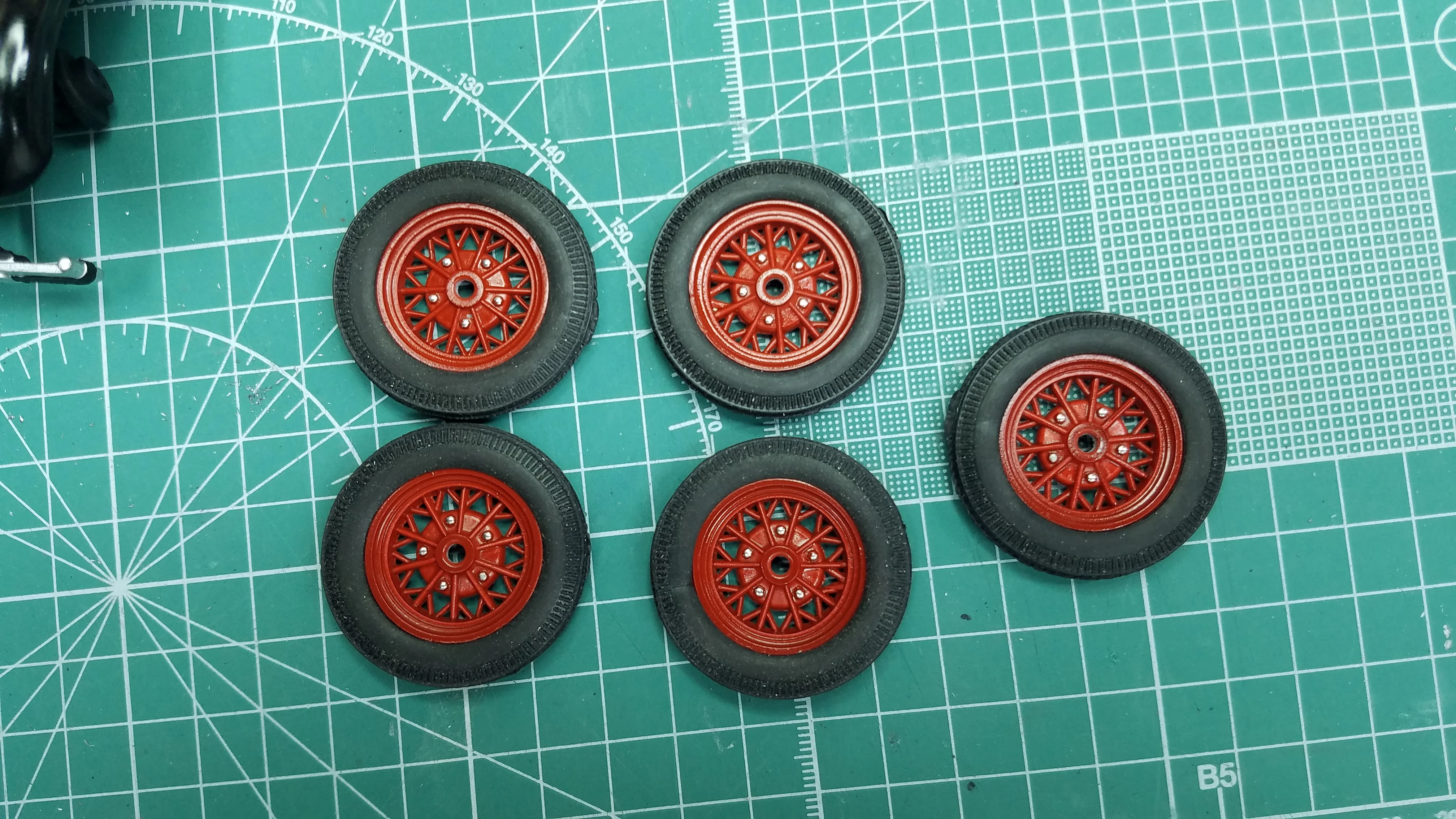
I used a Molotow chrome pen to highlight the lug nuts of the wheels, then I mounted the rubber tires to the wheels.
42 of 50
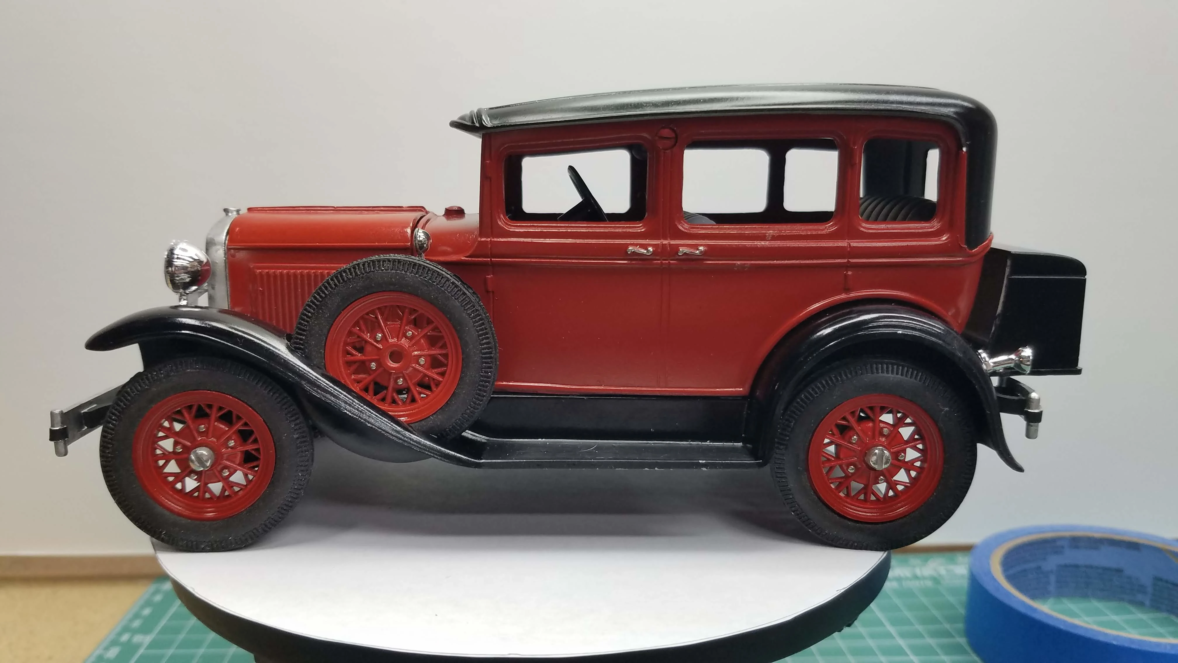
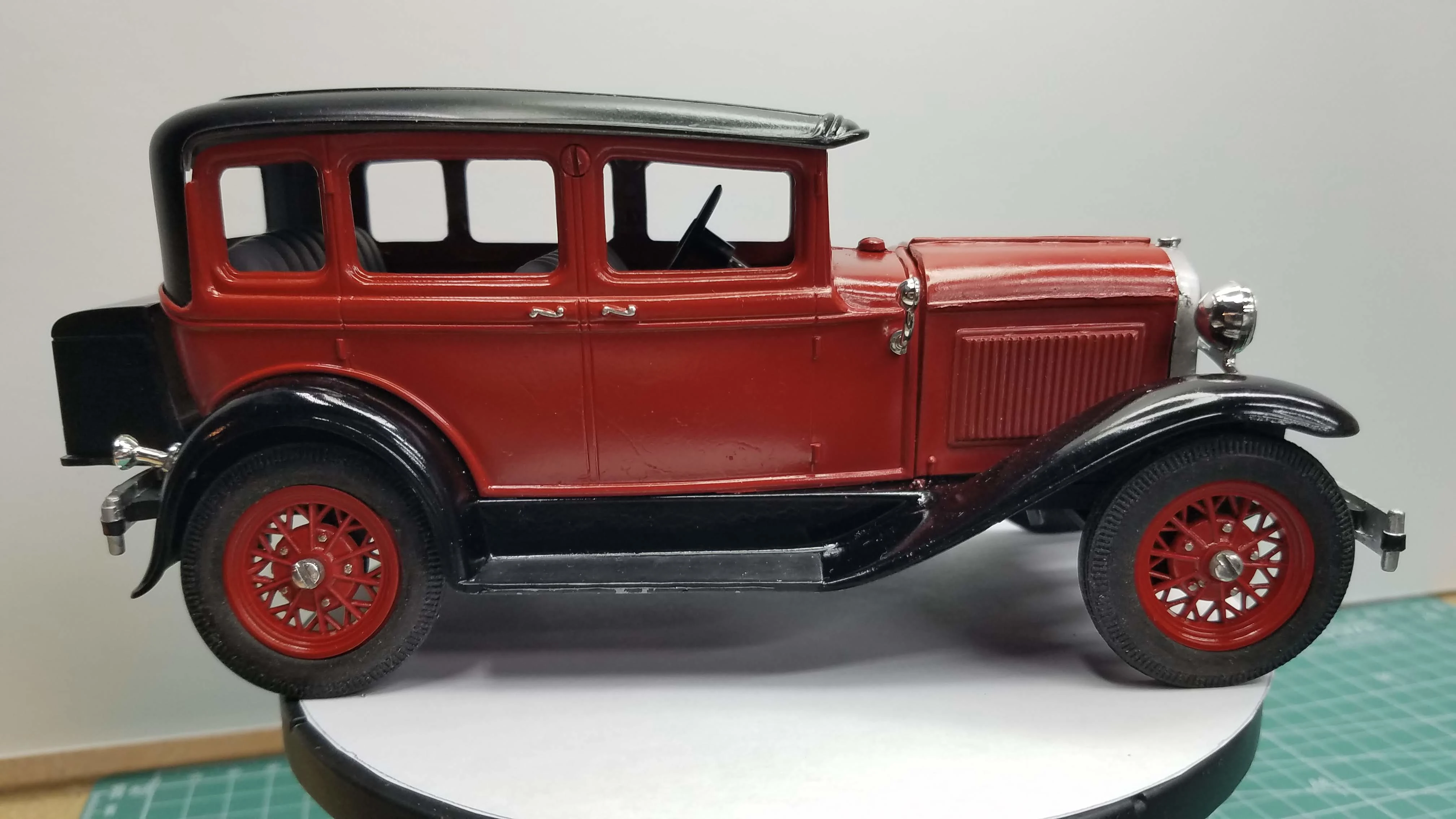
The wheels and the roof are mounted and the model is complete.
This and the next eight (8) photos are of the completed model
from various views and angles.
43 of 50
Completed model.

44 of 50
Completed model.
45 of 50
Completed model.
46 of 50
Completed model.
47 of 50
Completed model.
48 of 50
Completed model.
49 of 50
Completed model.
50 of 50
Completed model.